Videotec WASPT User manual

ENGLISHITALIANOFRANÇAISDEUTSCH
- Instructions manual
- Manuale di istruzioni
- Manuel d’instructions
- Bedienungslanleitung


Instructions manual - English - EN
1MNVKWASPT_1426_EN
ENGLISH
1 About this manual
Before installing and using this unit, please read this
manual carefully. Be sure to keep it handy for later
reference.
2 Notes on copyright and
information on trademarks
The quoted names of products or companies are
trademarks or registered trademarks.
3 Safety rules
• The manufacturer declines all responsibility
for any damage caused by an improper use
of the appliances mentioned in this manual.
Furthermore, the manufacturer reserves the right
to modify its contents without any prior notice.
The documentation contained in this manual has
been collected with great care, the manufacturer,
however, cannot take any liability for its use. The
same thing can be said for any person or company
involved in the creation and production of this
manual.
• The device must be installed only and exclusively
by qualied technical personnel.
• Before any technical work on the appliance,
disconnect the power supply.
• Do not use cables that seem worn or old.
• Never, under any circumstances, make any
changes or connections that are not shown in
this handbook. Improper use of the appliance
can cause serious hazards, risking the safety of
personnel and of the installation.

EN - English - Instructions manual
2 MNVKWASPT_1426_EN
• Use only original spare parts. Non-original spare
parts could cause re, electrical discharge or other
hazards.
• Before proceeding with installation check the
supplied material to make sure it corresponds
to the order specication by examining the
identication labels (4.2 Product markings, page 2).
• A disconnecting device, readily and easily
accessible, must be incorporated in the electrical
system of the building for rapid intervention.
4 Identification
Glass cleaning kit for ULISSE and ULISSE COMPACT
series pan & tilts and housings.
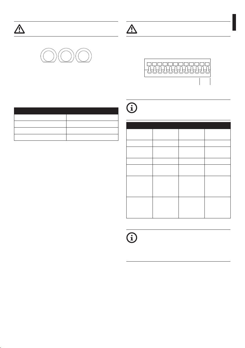
5l (1.3gal) o 23l (6gal) tank. Dierent pumps are
available for delivery up to 5m (16ft), 11m (36ft) or
30m (98ft). Available voltages in 230Vac, 24Vac or
120Vac. Pumps with 30m (98ft) delivery are available
only in 230Vac or 120Vac.
In the 11m (36ft) and 30m (98ft) delivery versions the
lack of liquid in the tank is signalled following the
automatic stop of the pump.
With the stand-alone housing (no P&T and no
telemetry receiver), it is possible to remotely control
via RS-485 the wiper and the washer pump by using
the DTWRX optional board.
See the label attached to the product.
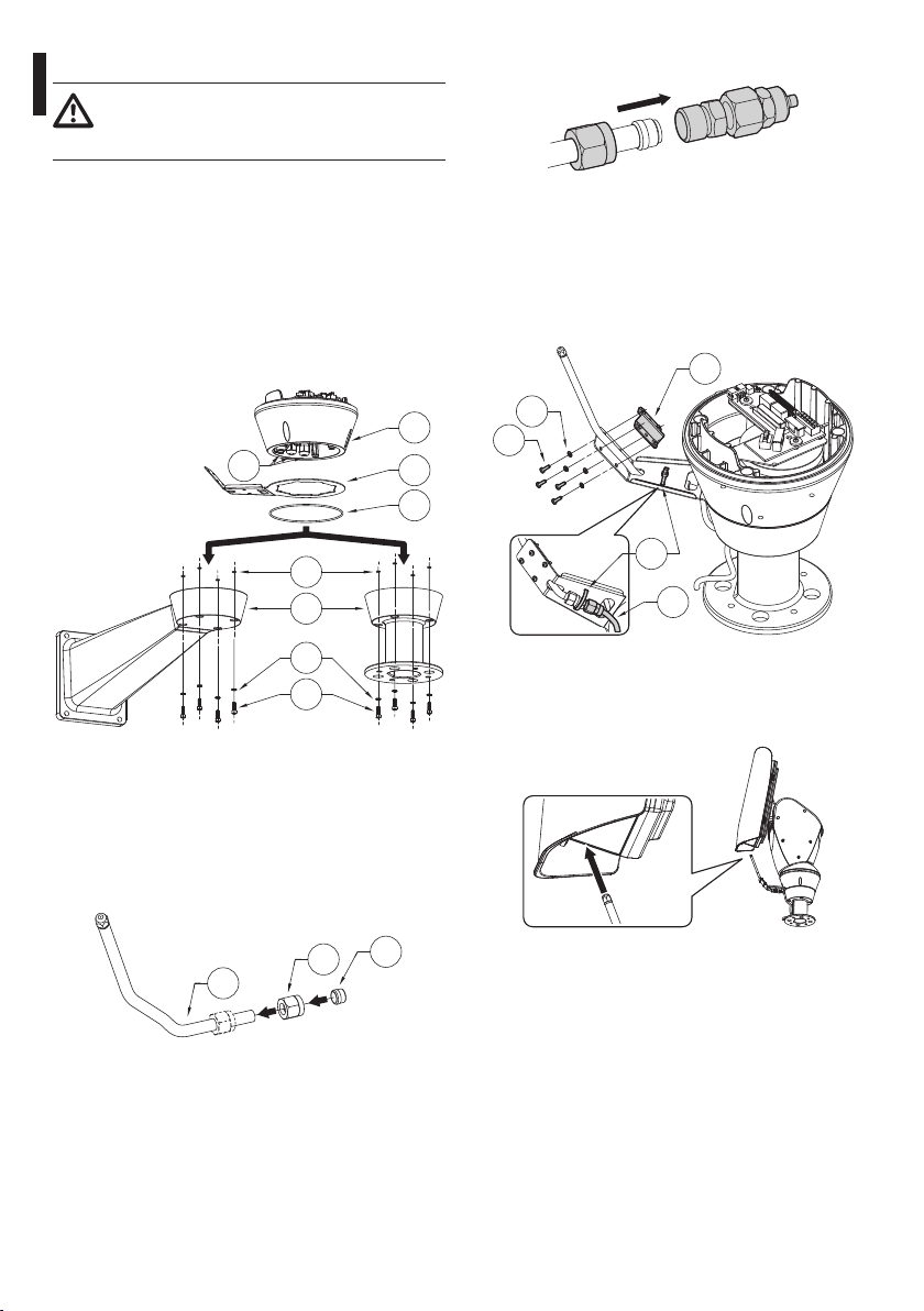
5 Preparing the product for
use
When the product is delivered, make sure that the
package is intact and that there are no signs that it
has been dropped or scratched.
If there are obvious signs of damage, contact the
supplier immediately.
Keep the packaging in case you need to send the
product for repairs.
Check the contents to make sure they correspond
with the list of materials as below:
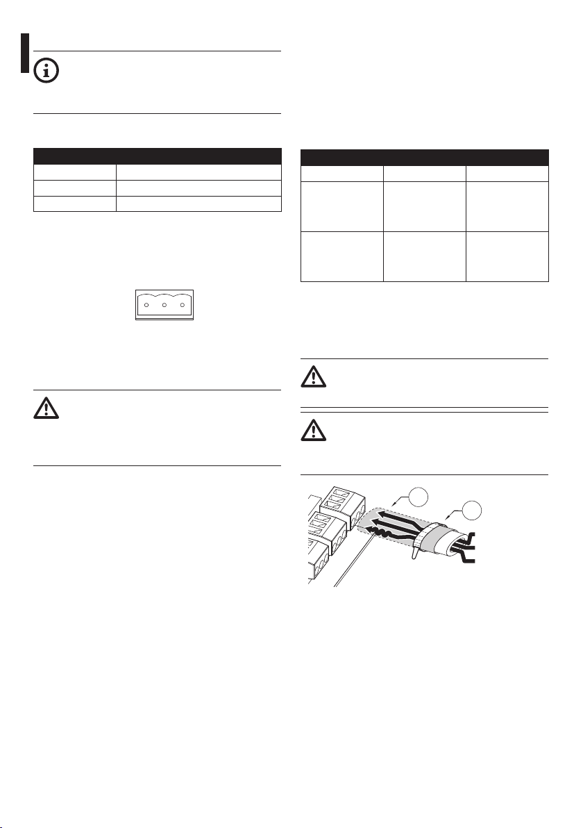
• Washer kit
• Ties
• Silicon sheath
• Pipe connector
• Washer pipe support
• Locking bracket for pipe support
• Delivery pipe
• Washer pipe (with nozzle)
• Bolts and screws
• Instructions manual
The packaging material can all be recycled. The
installer technician will be responsible for separating
the material for disposal, and in any case for
compliance with the legislation in force where the
device is to be used.
When returning a faulty product we recommend
using the original packaging for shipping.

Instructions manual - English - EN
3MNVKWASPT_1426_EN
6 Assembling and installing
Attach the metal cage (01) rmly to a wall using the
holes provided for this (02).
01
02
Water tank 5l (1.3gal), 5m (16ft) delivery.
01
02
Water tank 23l (6gal), 5m (16ft) or 11m (36ft) delivery.
01
02
Water tank 23l (6gal), 30m (98ft) delivery.
Take the plug out of the tank, along with any pumps
and level gauges. Remove the tank from the metal
cage.

EN - English - Instructions manual
4 MNVKWASPT_1426_EN
Depending on the version, the device can be
provided with dierent power supply voltages. Their
value is shown on the product identication label.
Open the cover of the water-proof box and connect
as described below.
Find the position of the following on the pump
control board: fuses (01), power supply terminal
J1(02), wiper connector J7(03), control terminal
J9(04) and DTWRX optional board connector J8(05).
01
05
04 0203

Instructions manual - English - EN
5MNVKWASPT_1426_EN
230V
FUS1
120V
FUS2
24V
FUS3
The board is supplied with the fuse in position FUS1
(for a 230Vac power supply).
If the power supply is dierent position the fuse
correctly referring to the following table.
230Vac Fuse in FUS1
120Vac Fuse in FUS2
24Vac Fuse in FUS3
Connect the Pan & Tilt to the J9 terminal contacts as
described in the table below.
J9
A B
RS485
GND
AVL
A2L
A1L
GCW
CW
GCP
CP
L2
L1
CP Pump control O1 R2A
GCP GND (pump
control)
C1 R2B
AVL Float alarm AL1 W
GND GND (oat
alarm)
COM/AGND G
A1L Float alarm
(clean con-
tact)
Alarm 1 (only
for ULISSE
NETCAM
family)
–
A2L Float alarm
(clean con-
tact)
ALARMS (only
for ULISSE
NETCAM
family)
–

EN - English - Instructions manual
6 MNVKWASPT_1426_EN
For the manual activation of the wiper, refer to the J9
terminal contacts (Fig. 7, page5).
CW Wiper control (clean contact)
GCW GND Wiper control (clean contact)
Join connector J7 to the wiper observing the order of
the PERM, SW and COM contacts (refer to the wiper
manual).
J7
PERM
SW
COM
WIPER
The optional DTWRX board allows you to turn the
wiper and the pump on remotely, from the keyboard.
This solution is particularly suitable for stand alone
housings. Insert the board into connector J8 and refer
to the following contacts on terminal J9 (Fig. 7, page
5).
RS-485-A Connector RS-485
A (+)
Connect to the
RS-485-A serial line
coming from the
keyboard
RS-485-B Connector RS-485
B (-)
Connect to the
RS-485-B serial line
coming from the
keyboard
The congurations of the optional board and
keyboard are described in the respective manuals.
01
02
Neutral (N)
Phase (L)
Earth

Instructions manual - English - EN
7MNVKWASPT_1426_EN
Connect the power supply terminal J1 to the electric
network using a suitably sectioned cable.
Fill the tank with water and insert it in the metal cage.
Insert the pump in the tank and tighten the cap.
The system is ready to be powered.
Adjust the position of the level controller and the
weight.
220mm
120mm
Fill the tank with water and insert it in the metal cage.
Put the pump and oat inside the tank and screw the
plug on.
The system is ready to be powered.
Adjust the position of the level controller and the
weight.
220mm
120mm
Fill the tank with water and insert it in the metal
cage, taking care to insert the male/female hydraulic
coupling (01) correctly. Put the oat inside the tank
and screw the plug on. Check the delivery hose
coupling for the pump (02) to make sure a small
quantity of water comes out.
02
01
Connect the supply pipe.
The system is ready to be powered.

EN - English - Instructions manual
8 MNVKWASPT_1426_EN
Fastening the support (01), place the washer pipe
support (03) in the desired position.
Insert the cables inside the support so that they
protrude by about 50cm. Insert the cable in the cable
glands (02). Keeping the base (04) at about 20cm
(7.9in) from the support, lock the cable glands. Set
the base up on the stand arranging the cables inside.
Attach the base to the support using the screws
supplied (05).
01
02 03
04
05
06
07
08
Cut the cables to size and either restore or make the
connections to the positioning unit.
Shorten the washer pipe (01) as needed. Unscrew the
nut (02) and slide it along the pipe. Insert the end of
the pipe into the ogive (03).
03
01
02
Lock the nut to the coupling.
Attach the pipe to the washer support using the
bracket (01), the screws (02) and the washers (03)
supplied.
Lock the coupling using the hoseclip (04) supplied
and connect the delivery hose (05).
01
02
03
04
05
To calibrate the jet direct the nozzle towards the glass
of the housing.
To start the washer refer to the pan & tilt manual.

Instructions manual - English - EN
9MNVKWASPT_1426_EN
Example of installation with wall bracket.
Pipe attached to the wall with a plate.
Position the nozzle support bracket (01) in the
appropriate groove on the base (02) and lock it using
the 2 screws (03). Remove the nozzle (04) from the
supplied pipe. Position the nozzle and lock it using
washer and nut (05). Install the gasket (07) on the
bottom hole on the bracket. Pass the supply pipe (06)
through the gasket and connect it to the nozzle.
02
04
06
07
01
05
03
Secure the supply pipe using the provided clamp.
Final washing position.
To start the washer refer to the pan & tilt manual.

EN - English - Instructions manual
10 MNVKWASPT_1426_EN
7 Maintaining and cleaning
The used fuse is described below.
• T 4A H 250V: BUSSMANN S505-4-R/OMEGA
GT520240
As an alternative, use an approved fuse featuring the
same characteristics.
The used fuses are described below.
• T 2A L 250V: BUSSMANN S506-2-R/OMEGA
ST522220
• T 4A L 250V: BUSSMANN S506-4-R/OMEGA
ST522240
As an alternative, use an approved fuse featuring the
same characteristics.
Once the box is open identify the fuse position.
Check the causes that caused the fuse breakage.
In the event the problem occurs again, contact the
technical assistance service.
8 Disposal of waste
materials
Your product is designed and manufactured with
high quality materials and components which can be
recycled and reused.
This symbol means that electrical and electronic
equipment, at their end-of-life, should be disposed of
separately from your household waste.
Please dispose of this equipment at your local
Community waste collection or Recycling centre.
In the European Union there are separate collection
systems for used electrical and electronic products.

Instructions manual - English - EN
11MNVKWASPT_1426_EN
9 Technical data
Polyethylene tank, stainless steel cage
Dimensions (WxHxL): 217x272x257mm
(8.5x10.7x10.1in)
Unit weight: 3.8kg (8.4lb)
Water tank capacity: 5l (1.3gal)
Delivery head: 5m (16ft) max
Tube length: 5m (16ft)
Power supply/Current consumption:
• 230Vac, 0.3A, 50/60Hz
• 120Vac, 0.6A, 50/60Hz
• 24Vac, 1.8A, 50/60Hz
Operating temperatures
• Maximum temperature: 60°C
• Minimum temperature (with antifreeze liquid in
solution, full performance): -10° (14°F)
• Minimum temperature (with antifreeze liquid in
solution, reduced performance): -25°C
Electrical safety (CE): EN60950-1
Outdoor installation (CE): EN60950-22
IP protection degree: EN60529, IP56
Polyethylene tank, stainless steel cage
Dimensions (WxHxL): 301x410x348mm
(11.8x16.1x13.7in)
Unit weight: 5.5kg (12.1lb)
Water tank capacity: 23l (6gal)
Delivery head: 5m (16ft) max
Tube length: 5m (16ft)
Power supply/Current consumption:
• 230Vac, 0.3A, 50/60Hz
• 120Vac, 0.6A, 50/60Hz
• 24Vac, 1.8A, 50/60Hz
Operating temperatures
• Maximum temperature: 60°C
• Minimum temperature (with antifreeze liquid in
solution, full performance): -10° (14°F)
• Minimum temperature (with antifreeze liquid in
solution, reduced performance): -25°C
Electrical safety (CE): EN60950-1
Outdoor installation (CE): EN60950-22
IP protection degree: EN60529, IP56

EN - English - Instructions manual
12 MNVKWASPT_1426_EN
Polyethylene tank, stainless steel cage
Dimensions (WxHxL): 301x410x348mm
(11.8x16.1x13.7in)
Unit weight: 6.7kg (14.8lb)
Water tank capacity: 23l (6gal)
Delivery head: 11m (36ft) max
Tube length: 11m (36ft)
Power supply/Current consumption:
• 230Vac, 0.5A, 50/60Hz
• 120Vac, 1A, 50/60Hz
• 24Vac, 3.8A, 50/60Hz
Operating temperatures
• Maximum temperature: 60°C
• Minimum temperature (with antifreeze liquid in
solution, full performance): -10° (14°F)
• Minimum temperature (with antifreeze liquid in
solution, reduced performance): -25°C
Electrical safety (CE): EN60950-1
Outdoor installation (CE): EN60950-22
IP protection degree: EN60529, IP56
Polyethylene tank, stainless steel cage
Dimensions (WxHxL): 301x620x348mm
(11.9x24.4x13.7in)
Unit weight: 15.1kg (33.3lb)
Water tank capacity: 23l (6gal)
Delivery head: 30m (98ft) max
Tube length: 30m (98ft)
Power supply/Current consumption:
• 230Vac, 2A, 50/60Hz
• 120Vac, 4.5A, 60Hz
Operating temperatures
• Maximum temperature: 60°C
• Minimum temperature (with antifreeze liquid in
solution, full performance): -10° (14°F)
Electrical safety (CE): EN60950-1
IP protection degree: EN60529, IPX4

Instructions manual - English - EN
13MNVKWASPT_1426_EN
10 Technical drawings
110257
15074
15066
272
Ø 8
177
235
272
217
88
Water tank 5l (1.3gal), 5m (16ft) delivery.
Ø 8
301348
269 200
152
410
136
Water tank 23l (6gal), 5m (16ft) delivery.

MNVKWASPT_1426_EN
Ø 8
301348
269 200
152
410
136
Water tank 23l (6gal), 11m (36ft) delivery.
348
269
301
200
Ø 8
620
210 410
152136
Water tank 23l (6gal), 30m (98ft) delivery.
Videotec S.p.A.
Via Friuli, 6 - I-36015 - Schio (VI) Italy
Tel. +39 0445 697411 - Fax +39 0445 697417
Email: [email protected]
www.videotec.com

Manuale di istruzioni - Italiano - IT
1MNVKWASPT_1426_IT
ITALIANO
1 Informazioni sul presente
manuale
Prima di installare e utilizzare questa unità, leggere
attentamente questo manuale. Conservare questo
manuale a portata di mano come riferimento futuro.
2 Note sul copyright e
informazioni sui marchi
commerciali
I nomi di prodotto o di aziende citati sono marchi
commerciali o marchi commerciali registrati
appartenenti alle rispettive società.
3 Norme di sicurezza
• Il produttore declina ogni responsabilità per
eventuali danni derivanti da un uso improprio
delle apparecchiature menzionate in questo
manuale. Si riserva inoltre il diritto di modicarne
il contenuto senza preavviso. Ogni cura è
stata posta nella raccolta e nella verica della
documentazione contenuta in questo manuale,
tuttavia il produttore non può assumersi alcuna
responsabilità derivante dall'utilizzo della stessa.
Lo stesso dicasi per ogni persona o società
coinvolta nella creazione e nella produzione di
questo manuale.
• L'installazione e la manutenzione del dispositivo
deve essere eseguita solo da personale tecnico
qualicato.
• Prima di eettuare interventi tecnici
sull'apparecchio togliere l'alimentazione elettrica.
• Non utilizzare cavi con segni di usura o
invecchiamento.
• Non eettuare per nessun motivo alterazioni o
collegamenti non previsti in questo manuale.
L'uso di apparecchi non idonei può portare a
gravi pericoli per la sicurezza del personale e
dell'impianto.

IT - Italiano - Manuale di istruzioni
2 MNVKWASPT_1426_IT
• Utilizzare solo parti di ricambio originali. Pezzi di
ricambio non originali potrebbero causare incendi,
scariche elettriche o altri pericoli.
• Prima di procedere con l'installazione controllare
che il materiale fornito corrisponda alle speciche
richieste esaminando le etichette di marcatura (4.2
Marcatura del prodotto, pagina 2).
• Un dispositivo di scollegamento, prontamente e
facilmente accessibile, deve essere incorporato
nell'impianto elettrico dell'edicio per un
intervento rapido.
4 Identificazione
Kit di lavaggio vetro per brandeggi della serie ULISSE
e ULISSE COMPACT e per custodie.
Tanica da 5l o 23l. Sono disponibili diverse pompe
con prevalenza no a 5m, 11m e 30m. Voltaggi
disponibili in 230Vac, 24Vac o 120Vac. Le pompe con
prevalenza 30m sono disponibili solo in 230Vac o
120Vac.
Le versioni con prevalenza 11m e 30m possiedono
un interruttore di livello del liquido per l'arresto
automatico della pompa.
Con custodia stand-alone (senza brandeggio e
ricevitore di telemetria) è possibile controllare
da remoto via RS-485 il tergicristallo e la pompa
lavavetro, utilizzando la scheda opzionale DTWRX.
Vedere l’etichetta posta sul prodotto.
5 Preparazione del
prodotto per l'utilizzo
Alla consegna del prodotto vericare che l'imballo
sia integro e non abbia segni evidenti di cadute o
abrasioni.
In caso di evidenti segni di danno all'imballo
contattare immediatamente il fornitore.
Conservare l'imballo nel caso sia necessario inviare il
prodotto in riparazione.
Controllare che il contenuto sia corrispondente alla
lista del materiale sotto elencata:
• Kit lavavetro
• Fascette
• Guaina siliconica
• Raccordo per tubo
• Sostegno tubo lavavetro
• Staa bloccaggio tubo lavavetro
• Tubo di mandata
• Tubo lavavetro (completo di ugello)
• Viteria
• Manuale di istruzioni
I materiali d'imballo sono costituiti interamente da
materiale riciclabile. Sarà cura del tecnico installatore
smaltirli secondo le modalità di raccolta dierenziata
o comunque secondo le norme vigenti nel Paese di
utilizzo.
In caso di restituzione del prodotto malfunzionante
è consigliato l'utilizzo dell'imballaggio originale per
il trasporto.

Manuale di istruzioni - Italiano - IT
3MNVKWASPT_1426_IT
6 Assemblaggio e
installazione
Fissare solidamente la gabbia metallica (01) ad una
parete mediante i fori appositamente predisposti
(02).
01
02
Tanica 5l, prevalenza 5m.
01
02
Tanica 23l, prevalenza 5m o 11m.
01
02
Tanica 23l, prevalenza 30m.
Togliere dalla tanica il tappo con eventuali pompa e
livellostato. Togliere la tanica dalla gabbia metallica.

IT - Italiano - Manuale di istruzioni
4 MNVKWASPT_1426_IT
A seconda della versione, al dispositivo possono
essere fornite diverse tensioni di alimentazione. Il
loro valore è riportato nell'etichetta identicativa del
prodotto.
Aprire il coperchio della scatola stagna ed eseguire i
collegamenti come descritto di seguito.
Localizzare sulla scheda di controllo della pompa la
posizione di: fusibili (01), morsetto di alimentazione
J1(02), connettore tergicristallo J7(03), morsetto
di controllo J9(04) e connettore J8per scheda
opzionale DTWRX (05).
01
05
04 0203
Other manuals for WASPT
2
Table of contents
Languages:
Other Videotec Washer manuals
Popular Washer manuals by other brands

Bosch
Bosch WAV28KH9IL user manual

Scandomestic
Scandomestic WAH 1707 W user manual

Hotpoint
Hotpoint G187 owner's manual

Wascomat
Wascomat Junior W 75 operating & maintenance manual

Siemens
Siemens WM12W469IL Instruction manual and installation instructions

Siemens
Siemens WG44G2A0ES User manual and installation instructions