Videotec UPTWAS01 User manual

Bedienungsanweisung
Manuel d’instructions
Operating instructions
Manuale istruzioni
Kit lavavetro per
unità di posizionamento ULISSE
Washer kit for
ULISSE positioning unit
Kit lave-vitre pour
unité de positionnement ULISSE
Scheibenwaschanlage für
die Positioniereinheit ULISSE

INSTALLAZIONE SERBATOIO POMPA
Il cablaggio dell’apparecchiatura deve essere effettuato soltanto
da personale qualificato ed in mancanza di tensione di alimentazione.
Mantenere uno schema di collegamento per successive consultazioni.
Non effettuare per nessun motivo alterazioni o collegamenti non previsti in
questo manuale.
Il mancato rispetto delle indicazioni fornite nel manuale in merito ai
collegamenti può portare a gravi pericoli per la sicurezza del personale e
dell’impianto.
Non modificare i cablaggi già presenti nel prodotto. Il mancato rispetto di
questa indicazione può portare a gravi pericoli per la sicurezza del personale
e dell’impianto, oltre a far decadere la garanzia.
Prevedere un idoneo dispositivo bipolare di sezionamento bipolare esterno
adeguatamente dimensionato.
Aggiungere all’acqua liquido antigelo di tipo automobilistico nel caso di
utilizzo a temperature inferiori a 3°C.
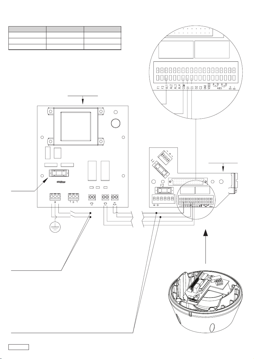
Nel caso sia necessario cambiare il fusibile, sostituire il componente “FUSE”
indicato nello schema. Il valore del fusibile è diverso a seconda del voltaggio
dell’apparecchiatura. Per il giusto valore, vedere la tabella in Fig. 1.
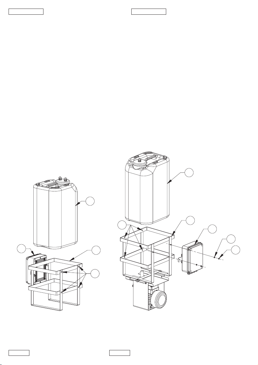
• Fissare solidamente (Fig. 2 e Fig. 3) la gabbia metallica (1) ad una parete mediante i 4
fori appositamente predisposti (2).
• Togliere dalla tanica il tappo con relativa pompa o livellostato.
• Togliere la tanica dalla gabbia metallica.
• Aprire il coperchio della scatola stagna (3) ed eseguire i collegamenti.
• Richiudere il coperchio.
INSTALLING THE PUMP TANK
Only skilled personnel should be allowed to wire up the equipment,
which should be disconnected from the power supply. Keep a copy of
the connection diagram for later consultation.
Never, for any reason whatsoever, make alterations or connections that
are not described in this handbook.
Failure to follow the instructions about connections as given in the
handbook may constitute a serious hazard to the safety of personnel
and of the system.
Do not change the wiring already present in the product. Failure to
follow this instruction may constitute a serious hazard to the safety of
personnel and of the system, and will also invalidate the guarantee.
Provide a suitably sized external bipolar disconnecting device.
If using the pump at temperatures below 3°C add some motor vehicle-
type antifreeze to the water.
If it is necessary to change the fuse, see the diagram where it is
marked "FUSE". The size of the fuse will vary according to the
voltage of the equipmaent. For the correct size, see the table in
Fig. 1.
• Attach the metal cage (1) firmly (Fig. 2 and Fig. 3) to a wall using the 4 holes
provided for this (2).
• Remove the cap from the tank with the corresponding pump or level controller.
• Remove the tank from the metal cage.
• Open the cover of the waterproof box (3) and make the connections.
• Replace the cover and close it.
ITALIANO ENGLISH
FRANCAIS DEUTSCH
INSTALLATION RÉSERVOIR POMPE
Le câblage de l’appareil doit exclusivement être effectué par un
personnel qualifié et après avoir sectionné la tension d’alimentation.
Conserver le schéma de connexion pour toute consultation
nécessaire.
N’effectuer sous aucun prétexte des modifications ou connexions non
prévues dans ce manuel.
Le non-respect des indications de ce manuel concernant les
connexions peut comporter des risques graves pour la sécurité du
personnel et de l'installation.
Ne pas modifier les câblages déjà prévus du produit. Le non-
respect de cette indication peut comporter des risques graves
pour la sécurité du personnel et de l'installation et annuler la
garantie.
Prévoir un dispositif bipolaire de sectionnement externe dimensionné
de façon adéquate.
Ajouter à l’eau du liquide antigel de type automobile en cas
d’utilisation à des températures inférieures à 3°C.
En cas de nécessité de changer le fusible, remplacer le composant
"FUSE" indiqué sur le schéma. La valeur du fusible diffère en fonction
de la tension de l’appareil. Pour la valeur correcte, se reporter au
tableau de la Fig. 1.
• Fixer solidement (Fig. 2 et Fig. 3) la cage métallique (1) à une paroi au moyen
des 4 orifices prévus à cet effet (2).
• Retirer le bouchon du jerrycan avec sa pompe ou son indicateur de niveau.
• Retirer le jerrycan de la cage métallique.
• Ouvrir le couvercle de la boîte étanche (3) et effectuer les connexions.
• Refermer le couvercle.
INSTALLATION DES PUMPENBEHÄLTERS
Das Gerät darf nur im spannungsfreien Zustand und nur von Fachleuten
verkabelt werden. Bitte bewahren Sie ein Anschlußschaltbild zum
späteren Nachschlagen auf.
Unter keinen Umständen Veränderungen oder Anschlüsse vornehmen,
die in diesem Handbuch nicht genannt sind.
Die Mißachtung der Angaben, die im Handbuch zu den Anschlüssen
gemacht werden, kann die Sicherheit des Personals und der Anlage
schwer gefährden.
Die produkteigenen Kabel dürfen nicht verändert werden. Die
Zuwiderhandlung gegen diese Vorgabe führt nicht nur zum Verlust
der Gewährleistungsrechte, sie kann auch das Personal und die Anlage
schwer gefährden.
Bringen Sie extern eine geeignete, angemessen dimensionierte
zweipolige Trenneinrichtung an.
Im Betrieb bei Temperaturen von unter 3 °C ist dem Wasser ein
Frostschutzmittel beizumischen, wie es für Automobile benutzt wird.
Falls die Schmelzsicherung ausgetauscht werden muß, ist die im
Schaltplan dargestellte Komponente "FUSE" zu erneuern. Der Ampere-
Wert der Sicherung hängt von der Voltzahl des Gerätes ab und kann
der Tabelle in Fig. 1 zutreffend entnommen werden.
• Den Metallkäfig (1) über die vorhandenen 4 Öffnungen (2) fest mit einer Wand
verbinden (Fig. 2 und Fig. 3).
• Den Verschluß mit Pumpe oder Standanzeige vom Kanister entfernen.
• Den Kanister vom Metallkäfig entfernen.
• Die Abdeckung des dicht schließenden Kastens (3) öffnen und die Anschlüsse
vornehmen.
• Die Abdeckung wieder schließen.

ALARM
CMD
COM
COM
COM
AL
LEVEL
+/
- /
L
N
L N Tr1 Tr2
ALIMENTAZIONE PRINCIPALE
MAIN SUPPLY
ALIMENTATION PRINCIPALE
HAUPTSTROMVERSORGUNG
QUESTO COLLEGAMENTO DEVE ESSERE
EFFETTUATO SOLO SE SI UTILIZZA UNA POMPA DELLA SERIE VIP25WASA
THIS CONNECTION SHOULD BE
MADE ONLY IF USING A PUMP IN THE VIP25WASA SERIES
CETTE CONNEXION DOIT UNIQUEMENT ÊTRE
EFECTUÉE EN CAS D’UTILISATION D’UNE POMPE DE LA GAMME VIP25WASA
DIESER ANSCHLUß MUß NUR VORGENOMMENWERDEN,
WENN EINE PUMPE DER BAUREIHE VIP25WASA ZUM EINSATZ KOMMT.
FUSIBILE
FUSE
FUSIBLE
SICHERUNG
SCHEDA POMPA
PUMP BOARD
POMPE CARTE
PUMPE-KARTE
SCHEDA ULISSE
ULISSE BOARD
ULISSE CARTE
ULISSE-KARTE
Fig. 1
Fuse 5mt 30mt
24V 1.25A -
120V 250mA -
230V 160mA 5A

Nel caso di pompa con prevalenza 5 metri:
• Riempire di acqua la tanica ed inserirla nella gabbia metallica.
• Inserire nella tanica la pompa ed avvitare il tappo.
• Il sistema é pronto per essere alimentato.
Nel caso di pompa con prevalenza 30 metri:
• Fissare (Fig. 3) la scatola stagna (3) alla gabbia metallica (1) tramite i dadi (4) e le
rondelle (5).
• Regolare la posizione del livellostato e del peso (Fig. 4).
• Riempire di acqua (Fig. 5) la tanica (6) e inserirla nella gabbia metallica facendo
attenzione di eseguire correttamente l’inserzione del raccordo idraulico (7)
maschio/femmina.
• Assicurarsi che dal raccordo di mandata della pompa (8) esca una piccola quantità
di acqua.
• Collegare il tubo di mandata.
• Il sistema é pronto per essere alimentato.
For a pump with a head of 5 metres:
• Fill the tank with water and insert it in the metal cage.
• Insert the pump in the tank and tighten the cap.
• The system is ready to be powered.
For a pump with a head of 30 metres:
• Attach (Fig. 3) the waterproof box (3) to the metal cage (1) using the nuts (4) and
washers (5).
• Adjust the position of the level controller and the weight (Fig. 4).
• Fill (Fig. 5) the tank (6) with water and insert it in the metal cage, taking care to
insert the male/female hydraulic coupling (7) correctly.
• Check the delivery hose coupling for the pump (8) to make sure a small quantity of
water comes out.
• Connect the delivery hose.
• The system is ready to be powered.
ITALIANO ENGLISH
POMPA PREVALENZA 5 METRI
DELIVERY PUMP 5 METERS
POMPE AVEC HAUTEUR D’ÉLÉVATION 5 MÈTRES
PUMPE MIT 5 METER FÖRDERHÖHE
2
31
6
Fig. 2
POMPA PREVALENZA 30 METRI
DELIVERY PUMP 30 METERS
POMPE AVEC HAUTEUR D’ÉLÉVATION 30 MÈTRES
PUMPE MIT 30 METER FÖRDERHÖHE
4
5
3
1
2
6
Fig. 3

FRANCAIS DEUTSCH
En cas de pompe avec prévalence de 5 mètres :
• Remplir le jerrycan d’eau et l’introduire dans la cage métallique.
• Introduire la pompe dans le jerrycan et visser le bouchon.
• Le système est prêt à être alimenté.
En cas de pompe avec prévalence de 30 mètres :
• Fixer (Fig. 3) la boîte étanche (3) à la cage métallique (1) au moyen des écrous (4)
et des rondelles (5).
• Régler la position de l’indicateur de niveau et du poids (Fig. 4).
• Remplir d’eau (Fig. 5) le jerrycan (6) et l’installer dans la cage métallique en ayant
soin d’insérer correctement le joint hydraulique (7) mâle/femelle.
• S’assurer qu’une petite quantité d’eau sort du raccord de refoulement de la
pompe (8).
• Connecter le tube d’entrée.
• Le système est prêt à être alimenté.
Bei einer Pumpe mit Förderhöhe 5 Meter:
• Den Kanister mit Wasser füllen und in den Metallkäfig einsetzen.
• Die Pumpe in den Kanister einsetzen und den Verschluß zuschrauben.
• Das System ist nun zur Speisung bereit.
Bei einer Pumpe mit Förderhöhe 30 Meter:
• Den dicht schließenden Kasten (3) mit Hilfe der Muttern (4) und Unterlegscheiben
(5) am Metallkäfig (1) befestigen (Fig. 3).
• Die Position der Standanzeige und des Gewichtes einstellen (Fig. 4).
• Den Kanister (6) mit Wasser füllen (Fig. 5) und in den Metallkäfig einsetzen. Achten Sie
darauf, daß der Wasseranschluß (7) mit Vater- und Mutterteil korrekt eingesetzt wird.
• Überzeugen Sie sich, daß aus dem Vorlaufanschluß der Pumpe (8) eine kleine
Menge Wasser austritt.
• Die Vorlaufleitung anschließen.
• Das System ist nun bereit, gespeist zu werden.
220 mm / 8.6 in
120 mm / 4.7 in
Fig. 4
8
7
6
Fig. 5

INSTALLAZIONE LAVAVETRO
Per fissare (Fig. 6) la base al supporto utilizzare le nuove viti in
dotazione (13) e controllare che siano presenti le rondelle (14), le
guarnizioni per viti (15) e la guarnizione (16).
• Dopo aver fissato il supporto (9, staffa o supporto a colonna), posizionare il
sostegno tubo lavavetro (11) nella posizione desiderata come in Fig. 6.
• Introdurre i cavi all'interno del supporto in modo che fuoriescano per circa mezzo
metro.
• Introdurre i cavi all'interno dei pressacavi (10) e tenendo la base (12) a circa 20 cm
dal supporto serrare i pressacavi.
• Sistemare la base sul supporto aiutando i cavi a posizionarsi all'interno.
• Fissare la base sul supporto utilizzando le nuove viti in dotazione (13).
• Tagliare a misura i cavi e ripristinare o effettuare i collegamenti dell’unità di
posizionamento.
• Una volta fissata la base al supporto, accorciare (Fig. 7) il tubo del lavavetro (17)
secondo necessità e fissarlo al raccordo nel seguente modo: svitare il dado (18) dal
raccordo, inserirlo nel tubo e inserire l’estremità del tubo sull’ogiva (19). Serrare
(Fig. 8) il dado al raccordo (20).
• Fissare (Fig. 9) il tubo al sostegno lavavetro tramite la staffetta (21), le viti (22) e
le rondelle (23) in dotazione.
• Bloccare il raccordo tramite la fascetta (24) in dotazione e collegare il tubo di
mandata (25).
• Per calibrare il getto (Fig. 10) orientare l’ugello (26) verso il vetro della custodia.
INSTALLING THE WASHER
To attach the base to the support (Fig. 6) use the new screws provided
(13) and make sure the washers (14) are present, as well as the screw
seals (15) and the gasket (16).
• After attaching the support (9, bracket or column support), position the washer
pipe support in the desired position as in Fig. 6.
• Insert the cables inside the support so that they protrude by about half a metre.
• Insert the cable in the cable glands (10) and, keeping the base (12) at about 20
cm from the support, lock the cable glands.
• Set the base on the support, aiding the cables to achieve the correct position inside.
• Attach the base to the support using the new screws supplied (13).
• Cut the cables to size and either restore or make the connections to the
positioning unit.
• When you have attached the base to the support, shorten (Fig. 7) the washer pipe
(17) as required and attach it to the coupling as follows: undo the nut (18) from
the coupling, insert it into the pipe and insert the end of the pipe on the nosecap
(19). Lock (Fig. 8) the nut to the coupling (20).
• Attach (Fig. 9) the pipe to the washer support using the bracket (21), the screws
(22) and the washers (23) supplied.
• Lock the coupling using the hoseclip (24) supplied and connect the delivery
hose (25).
• To calibrate the jet (Fig. 10) direct the nozzle (26) towards the glass of the
housing.
ITALIANO ENGLISH
Fig. 6
16
11
12
10
15
14
13
9

21
25
23
22
24
Fig. 9
FRANCAIS DEUTSCH
INSTALLATION LAVE-VITRE
Pour fixer (Fig. 6) la base au support, utiliser les nouvelles vis fournies
(13) et contrôler la présence des rondelles (14), des garnitures vis (15)
et de la garniture (16).
• Après avoir fixé le support (9, bride ou support à colonne), positionner le support
tube lave-vitre (11) en position désirée comme sur la Fig. 6.
• Introduire les câbles à l’intérieur du support de façon à ce qu’ils dépassent sur
environ 50 cm.
• Introduire les câbles à l’intérieur des presse-câbles (10) en tenant la base (12) à
environ 20 cm du support et serrer les presse-câbles.
• Installer la base sur le support en positionnant les câbles à l’intérieur.
• Fixer la base sur le support au moyen des nouvelles vis fournies (13).
• Couper les câbles à la longueur requise ou effectuer les connexions de l’unité de
positionnement.
• Après avoir fixé la base au support, raccourcir (Fig. 7) le tube du lave-vitre (17)
selon les nécessités et le fixer au raccord de la façon suivante : desserrer l’écrou
(18) du raccord, l’insérer dans le tube et introduire l’extrémité du tube sur l’ogive
(19). Serrer (Fig. 8) l’écrou au raccord (20).
• Fixer (Fig. 9) le tube au support lave-vitre au moyen de la bride (21), des vis (22)
et des rondelles (23) fournies.
• Bloquer le raccord au moyen du collier (24) fourni et connecter le tube de
refoulement (25).
• Pour calibrer le jet (Fig. 10) orienter la buse (26) vers la vitre du caisson.
INSTALLATION DER SCHEIBENWASCHANLAGE
Zur Fixierung (Fig. 6) der Basis an der Halterung verwenden Sie bitte die
neuen Schrauben aus dem Lieferumfang (13) und kontrollieren Sie, ob die
Unterlegscheiben (14), die Schraubendichtungen (15) und die Dichtung (16)
vorhanden sind.
• Nach der Befestigung der Halterung (9, Bügel oder Haltesäule) die Stütze des
Scheibenwaschschlauches (11) an der gewünschten Stelle positionieren, siehe Fig. 6.
• Die Kabel so ins Innere der Halterung einführen, daß sie etwa einen halben Meter
hervorstehen.
• Die Kabel in die Kabelklemmen (10) einführen und die Basis (12) ungefähr 20 cm von der
Halterung entfernt festhalten. Gleichzeitig die Kabelklemmen festziehen.
• Die Basis auf der Halterung einrichten, dabei die Kabel bei der Positionierung im Innern
unterstützen.
• Die Basis mit den neuen, im Lieferumfang enthaltenen Schrauben (13) auf der Halterung
fixieren.
• Die Kabel auf Maß schneiden und die Anschlüsse der Positioniereinheit erneut oder
erstmalig herstellen.
• Wenn die Basis an der Halterung befestigt ist, die Leitung der Scheibenwaschanlage (17)
nach Bedarf kürzen (Fig. 7) und folgendermaßen am Anschluß festmachen: Die Mutter
(18) vom Anschlußstück schrauben, dieses in das Rohr einführen und das Leitungsende auf
den Dichtkegel (17) setzen. Die Mutter auf dem Anschlußstück (20) festschrauben (Fig. 8).
• Die Leitung mit dem Bügel (21), den Schrauben (22) und den Unterlegscheiben (23), alles
im Lieferumgang enthalten, an der Stütze der Scheibenwaschanlage fixieren (Fig. 9).
• Das Anschlußstück mit Hilfe der beiliegenden Schelle (24) sichern und die Vorlaufleitung
(25) anschließen.
• Zur Kalibrierung des Strahls (Fig. 10) die Düse (26) auf die Gehäusescheibe richten.
17
18 19
20
Fig. 8
Fig. 7

Fig. 11 Fig. 12
26
Fig. 10

Fig. 13

SPECIFICHE TECNICHE
POMPA PREVALENZA 5 METRI:
-Materiale: Tanica in polietilene
Gabbia in acciaio inox
-Dimensioni esterne: 350x301x458 mm
-Temperatura d’esercizio: Da +3°C a +50°C
-Peso: 5,4 kg
-Alimentazione: 115/230V AC, 50/60 Hz, 12 W o 24V AC, 50/60 Hz, 12W
-Grado di protezione: IP56
-Prevalenza: 5 m
POMPA PREVALENZA 30 METRI:
-Materiale: Tanica in polietilene
Gabbia in acciaio inox
-Dimensioni esterne: 710x300x270 mm
-Temperatura d’esercizio: Da +3°C a +50°C
-Peso: 12,4 kg
-Alimentazione: 115/230V AC, 50 Hz, 600 W
-Grado di protezione: IP45
-Prevalenza: 30 m
ITALIANO ENGLISH
FRANCAIS DEUTSCH
TECHNICAL SPECIFICATIONS
DELIVERY PUMP 5 METERS:
-Materials: Polyethylene Tank
Stainless steel cage
-External dimensions: 350x301x458 mm / 13.8x11.8x18 in
-Working temperature: From +3°C to +50°C / From +37°F to +122°F
-Weight: 5,4 kg / 11.9 lb
-Power supply: 115/230V AC, 50/60 Hz, 12 W or 24V AC, 50/60 Hz, 12W
-Protection rating: IP56
-Delivery: 5 m / 16.4 ft
DELIVERY PUMP 30 METERS:
-Materials: Polyethylene Tank
Stainless steel cage
-External dimensions: 710x300x270 mm / 28x12x11 in
-Working temperature: From +3°C to +50°C / from +37°F to +122°F
-Weight: 12.4 kg / 27.3 lb
-Power supply: 115/230V AC, 50 Hz, 600 W
-Protection rating: IP45
-Delivery: 30 m / 98 ft
SPÉCIFICATIONS TECHNIQUES
POMPE AVEC HAUTEUR D’ÉLÉVATION 5 MÈTRES:
-Matériel: Réservoir en polyéthylène
Cage en acier inox
-Dimensions externes: 350x301x458 mm
-Température d'utilisation: De +3°C à +50°C
-Poids: 5,4 kg
-Alimentation: 115/230V AC, 50/60 Hz, 12 W ou 24V AC, 50/60 Hz, 12W
-Degré de protection: IP56
-Hauteur d’élévation: 5 m
POMPE AVEC HAUTEUR D’ÉLÉVATION 30 MÈTRES:
-Matériel: Réservoir en polyéthylène
Cage en acier inox
-Dimensions externes: 710x300x270 mm
-Température d'utilisation: De +3°C à +50°C
-Poids: 12,4 kg
-Alimentation: 115/230V AC, 50 Hz, 600 W
-Degré de protection: IP45
-Hauteur d’élévation: 30 m
TECHNISCHE DATEN:
PUMPE MIT 5 METER FÖRDERHÖHE
-Werkstoff: Polyäthylentank
Rostfreibehälter
-Außenabmessungen: 350x301x458 mm
-Gebrauchstemperatur: Von +3°C bis +50°C
-Gewicht: 5,4 kg
-Spannungsversorgung: 115/230V AC, 50/60 Hz, 12 W oder 24V AC, 50/60 Hz, 12W
-Schutzart: IP56
-Förderhöhe: 5 m
PUMPE MIT 30 METER FÖRDERHÖHE
-Werkstoff: Polyäthylentank
Rostfreibehälter
-Außenabmessungen: 710x300x270 mm
-Gebrauchstemperatur: Von +3°C bis +50°C
-Gewicht: 12,4 kg
-Spannungsversorgung: 115/230V AC, 50 Hz, 600 W
-Schutzart: IP45
-Förderhöhe: 30 m

POMPA PREVALENZA 5 METRI
DELIVERY PUMP 5 METERS
POMPE AVEC HAUTEUR D’ÉLÉVATION 5 MÈTRES
PUMPE MIT 5 METER FÖRDERHÖHE
347.5
458
152135.5
200
Ø 8
269
POMPA PREVALENZA 30 METRI
DELIVERY PUMP 30 METERS
POMPE AVEC HAUTEUR D’ÉLÉVATION 30 MÈTRES
PUMPE MIT 30 METER FÖRDERHÖHE
200
269
458
152135.5
225
683
Ø 8
Fig. 14
Fig. 15

MNVKUPTWAS_0625
Il produttore declina ogni responsabilità per eventuali danni derivanti da un uso improprio delle
apparecchiature menzionate in questo manuale. Si riserva inoltre il diritto di modificarne il contenuto senza
preavviso. Ogni cura é stata posta nella raccolta e nella verifica della documentazione contenuta in questo
manuale, tuttavia il produttore non può assumersi alcuna responsabilità derivante dall’utilizzo della stessa.
Lo stesso dicasi per ogni persona o società coinvolta nella creazione e nella produzione di questo manuale.
The manufacturer declines all responsibility for any damage caused by an improper use of the
appliances mentioned in this manual. Furthermore, the manufacturer reserves the right to modify
its contents without any prior notice. The documentation contained in this manual has been collected
with great care, the manufacturer, however, cannot take any liability for its use. The same thing can
be said for any person or company involved in the creation and production of this manual.
Le producteur décline toute responsabilité pour les dommages éventuels dus à une utilisation non appropriée
des appareils mentionnés dans ce manuel. On réserve en outre le droit d’en modifier le contenu sans préavis.
La documentation contenue dans ce manuel a été rassemblée et vérifiée avec le plus grand soin, cependant,le
producteur ne peut pas s’assumer aucune responsabilité dérivante de l’emploi de celle-là. La même chose
vaut pour chaque personne ou société impliquées dans la création et la production de ce manuel.
Der Hersteller lehnt jede Haftung für eventuelle Schäden ab, die aufgrund unsachgemäßer Anwendung
der in diesem Handbuch erwähnten Geräte entstanden ist. Ferner behält er sich das Recht vor, den Inhalt
ohne Vorkündigung abzuändern. Die Dokumentation in diesem Handbuch wurde sorgfältig ausgeführt und
überprüft, dennoch kann der Hersteller keine Haftung für die Verwendung übernehmen. Dasselbe gilt für jede
Person oder Gesellschaft, die bei der Schaffung oder Produktion von diesem Handbuch miteinbezogen ist.
ITALIANO ENGLISH
FRANCAIS DEUTSCH
This manual suits for next models
2
Other Videotec Washer manuals