Viessmann Solar-Divicon Quick guide

Installation and
service instructions
Solar−Divicon, part no.7188391 and 7188392,
Solar circuit pump line, part no.7188393 and 7188394
Safety instructions
¨Please observe these safety instructions.
Installation, initial start−up, inspection,
maintenance and repairs must be
carried out by a competent person
(heating engineer/installation
contractor).
Before working on the equipment/
heating system, isolate the power
supply (e.g. by removing a separate
mains fuse or by means of a mains
isolator) and safeguard against
unauthorised reconnection.
When using gas as fuel, also close
the main shut−off valve and safeguard
against unauthorised reopening.
It is not permitted to carry out repairs
on parts that fulfil a safety function.
For replacements, use only original
spare parts from Viessmann or those
which are approved by Viessmann.
Dimensions
ASolarDivicon
BSafety assembly
CSolar circuit pump line
5862810GB5/2005 Please keep safe
380
240
0
20
40 60 80
100
120 0
20
40 60 80
100
120
380
210
0
20
40 60 80
100
120
A
B
C

2
Assembly and installation information
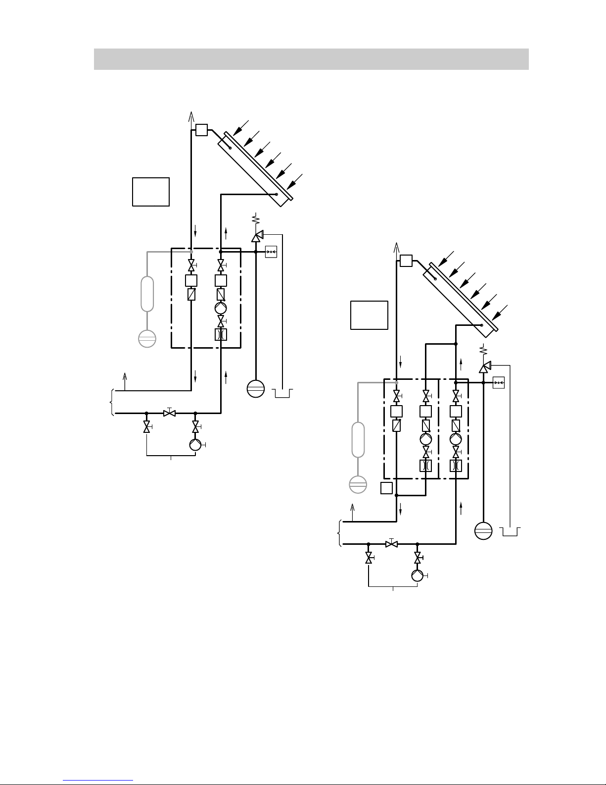
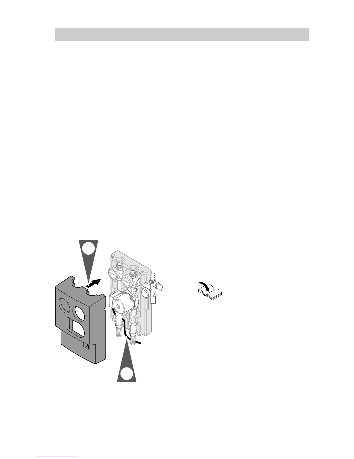
HThe Solar−Divicon comprises:
pre−assembled and sealed valves
and safety assembly
Flow regulating valve to control
the solar heating system during
the initial start−up and operation
Non−return valve in the flow and
return pipe
HAlways install Solar−Divicon so that
steam cannot enter the expansion
vessel in the event of stagnation.
HThe Solar−Divicon and the solar
circuit pump line are not suitable
for direct contact with swimming
pool water.
HFlush the system with process
medium after draining.
HIf the expansion vessel is installed
as high or higher than the
Solar−Divicon, a thermal insulation
loop is required.
HA pre−cooling vessel connection is
fitted to the flow line to protect the
expansion vessel against excess
temperatures.
HUse only gunmetal, brass fittings,
copper pipes or Viessmann
stainless steel solar circuit pipes
for the installation. Never use
galvanized/zinc−plated pipes,
fittings or graphitised gaskets. Use
hemp only in conjunction with
pressure and temperature−resistant
sealants (e.g. ViscotexSolarpaste,
Locher & Co. AG, CH9450Altstätten).
Components that come in contact
with process medium must be
resistant to the medium.
HCheck the sealing surfaces for
cleanliness and damage before
assembly.
Installation of the locking ring fittings
HAll pipes must be cut at a right
angle and deburred.
HInsert the support sleeves into the
pipework.
HPush the union nut and the locking
ring onto the pipe and lightly
lubricate the threads with oil.
HPush the pipe into the locking ring
fitting as far as it will go.
HInitially turn the union nut by hand,
then tighten with an open ended
spanner by a further ¾ turn.
HNever fit annealed copper pipes
onto the locking ring fittings.
5862810GB

3
Assembly and installation information (cont.)
System with SolarDivicon
ASolarDivicon
BSolar circuit pump line
CCollector
DExpansion vessel
EManual solar fill pump
FFill valve
GShut−off valve
HDrain valve
KFilling assembly
LConnections to the DHW cylinder
MAir separator
NSolar control unit
OAir vent valve
PPre−cooling vessel (if required)
System with SolarDivicon and solar
circuit pump line
Position the solar circuit pump line
to the right near the Solar−Divicon.
The Solar−Divicon pump acts as a
bypass pump, the solar circuit pump
line pump as a solar circuit pump. In
this case fit the safety assembly onto
the solar circuit pump line.
RL Return
VL Flow
5862810GB
A
C
O
N
L
M
G
K
F
E
D
TT
T
VL RL
H
P
D
B
C
O
L
M
G
K
F
E
D
TT
VL RL
T
T
A
H
T
N
P
D

4
Fitting the Solar−Divicon
5862810GB
or
8mm
or
5.
3.
4.
1.
2.
3.

5
Fitting the Solar−Divicon (cont.)
1. Pull the upper section of the
thermal insulation forwards.
2. Secure the valve assembly
together with the lower part of the
thermal insulation.
3. Installation with copper pipes
Insert the support sleeves into the
interconnecting pipes of the solar
circuit.
Alternative:
Installation with stainless steel
solar circuit pipe
Trim (free of burrs) in the valley of
the corrugation; do not damage
the peak of the corrugation. Fit the
union nut, half washer (in the fifth
valley) and O−rings (in the first and
third valley).
4. Insert a support sleeve into the
connection pipe to the expansion
vessel and secure on the safety
assembly.
5. Secure the blow−off line with the
safety valve from the safety
assembly; ensure the correct
orientation of the locking ring.
Note
The blow−off line must terminate
in an open container.
6. Route the connecting cable for the
circulation pump downwards
through the cable duct and
connect to the solar control unit.
Installation and service
instructions solar
control unit
7. Push the thermal insulation over
the valve assembly.
8. Push the thermal insulation of the
pipework into the recesses of the
thermal insulation of the
Solar−Divicon.
5862810GB
6.
7.

6
Fitting the solar circuit pump line
5862810GB
8mm
or
1.
4.
5. 1.
1.
2.
3.
or
4.
5.

7
Fitting the solar circuit pump line (cont.)
1. Pull the upper section of the
thermal insulation forward and
remove the valve assembly.
2. Secure the retaining plate.
3. Insert the valve assembly.
4. Installation with copper pipes
Insert the support sleeves into the
interconnecting pipes of the solar
circuit.
Alternative:
Installation with stainless steel
solar circuit pipe
Trim (free of burrs) in the valley of
the corrugation; do not damage
the peak of the corrugation.
Fit the union nut, half washer (in
the fifth valley) and O−rings (in the
first and third valley).
5. Slide the thermal insulation under
the assembly.
Follow the instructions below or
those on page8.
Fitting the solar circuit pump line separately or on
the left next to the Solar−Divicon.
5862810GB
6.
8.
7.

8
Fitting the solar circuit pump line (cont.)
6. Close the opening of the solar
circuit pump line with the cap and
the flat packing supplied.
7. Route the connecting cable for the
circulation pump downwards
through the cable duct and
connect to the solar control unit.
Installation and service
instructions solar
control unit
8. Push the thermal insulation over
the valve assembly and click it into
place.
9. Push the thermal insulation of the
pipework into the recesses of the
thermal insulation of the pump
line.
Fitting the solar circuit pump line to the right next to the
Solar−Divicon
5862810GB
9.
8.
7.
6.
10.

9
Fitting the solar circuit pump line (cont.)
6. Dismantle the safety assembly of
the Solar−Divicon and secure it on
the solar circuit pump line.
7. Close the opening of the return
line of the Solar−Divicon with the
cap and the insert.
8. Insert a support sleeve into the
connection pipe to the expansion
vessel and secure on the safety
assembly.
9 Secure the blow−off line on the
safety valve of the safety
assembly; ensure the correct
orientation of the locking ring.
Note
The blow−off line must terminate
in an open container.
10. Route the connecting cable for
the circulation pump downwards
through the cable duct and
connect to the solar control unit.
Installation and service
instructions solar
control unit
11. Remove the knock−out for the
safety assembly.
12. Push the thermal insulation over
the valve assembly and click it
into place.
13. Push the thermal insulation of
the pipework into the recesses of
the thermal insulation of the
pump line.
5862810GB
12.

10
Commissioning
Flushing and draining the solar heating system
Turn the integral non−return valves in the flow and return lines to "ON" by
turning the thermometer 45ºclockwise.
Pump curves
Match the flow rate via the output stages of the circulation pump to the
number of collectors or collector surface area.
"Vitosol" service instructions
APressure drop curve of the Solar−Divicon
5862810GB
Pump rate in l/h
0 500 1000 1500 2000 2500
0 0.5 1.0 1.5 2.0 2.5
Type PS 10 or P 10 A
Head in m
0
7
1
2
3
4
5
6
Pump rate in m3/h

11
Commissioning (cont.)
APressure drop curve of the Solar−Divicon
5862810GB
0 500 1000 1500 2000
0 0.5 1.0 1.5 2.0
Head in m
0
1
2
3
4
5
6
7
8
9
10
Type PS 20 or P 20
A
2.5
2500
Pump rate in l/h
Pump rate in m3/h

12
SolarDivicon parts list
When ordering spare parts:
Quote the part no. and the item no.
of the required part (as per this parts
list). Obtain standard parts from your
local supplier.
Parts
001 Locking ring fitting with support
sleeves
002 Thermal insulation pieces
003 Flow ball valve (with item 004)
004 Thermometer
005 Flow rate indicator
006 Circulation pump
007 Gasket set
008 Safety assembly
009 Return ball valve (with item004)
010 Pressure gauge
Parts not shown
011 Half washer pack
012 Installation and service
instructions
5862810GB

13
SolarDivicon parts list (cont.)
5862810GB

14
Solar circuit pump line parts list
When ordering spare parts:
Quote the part no. and the item no.
of the required part (as per this parts
list). Obtain standard parts from your
local supplier.
Parts
001 Locking ring fitting with support
sleeves
002 Thermal insulation shells
004 Thermometer
005 Flow rate indicator
006 Circulation pump
007 Gasket set
009 Return ball valve (with item004)
Parts not shown
011 Half washer pack
012 Installation and service
instructions
5862810GB

15
Solar circuit pump line parts list (cont.)
5862810GB
007
004
001
006
009
001
005
007
007
007
002

Viessmann Werke GmbH&Co KG
D35107 Allendorf
Tel: +49 6452 700
Fax: +49 6452 702780
www.viessmann.de
Viessmann Limited
Hortonwood 30, Telford
Shropshire, TF1 7YP, GB
Tel: +44 1952 675000
Fax: +44 1952 675040
E−mail: info−[email protected]
16
Specification
SolarDivicon Type PS10 PS20
Solar circuit pump line Type P10 P20
Grundfos circulation pump 2560 2580
Rated voltage V~ 230 230
Power consumption
at output stages I, II, III
WI40
II 60
III 75
I 140
II 210
III 245
Max. pump rate m3/h 3.7 2.8
Max. head m 5.8 8
Flow rate indicator litres/
min
2 to 12 7 to 30
Safety valve (only for Solar−Divicon) bar 6 6
Max. operating temperature ºC 120 120
Max. operating pressure bar 6 6
Connections ∅
HSolar circuit (locking ring fitting/
stainless steel solar circuit pipe)
HExpansion vessel
(only for Solar−Divicon)
mm
mm
22
22
22
22
5862810GBSubject to technical modifications.
Printed on environmentally friendly,
chlorine−free bleached paper
This manual suits for next models
8
Table of contents
Popular Water System manuals by other brands

Xylem
Xylem Lowara ecocirc S Additional Installation, Operation and Maintenance Instructions

KSB
KSB BOA-H operating manual

DIRECT COIL
DIRECT COIL WATER COILS Installation and operating manual

gledhill
gledhill PulsaCoil 145 Design, installation & servicing instructions

ITT
ITT LX Series Installation and operating instructions

Marco
Marco 1000859 quick start guide

Grundfos
Grundfos UPM3 instructions

Thermo Scientific
Thermo Scientific Barnstead Nanopure TOC - UV Operation manual

EcoWater
EcoWater eVOLUTION Series instructions

APLOS
APLOS ANGEL 600 GPD instruction manual

Battery Watering Technologies
Battery Watering Technologies Direct Fill Link+ manual

PUREWASH
PUREWASH ALTO 10 Getting started