3
IMPORTANT - Please Read and Follow!
DANGER
CAUTION
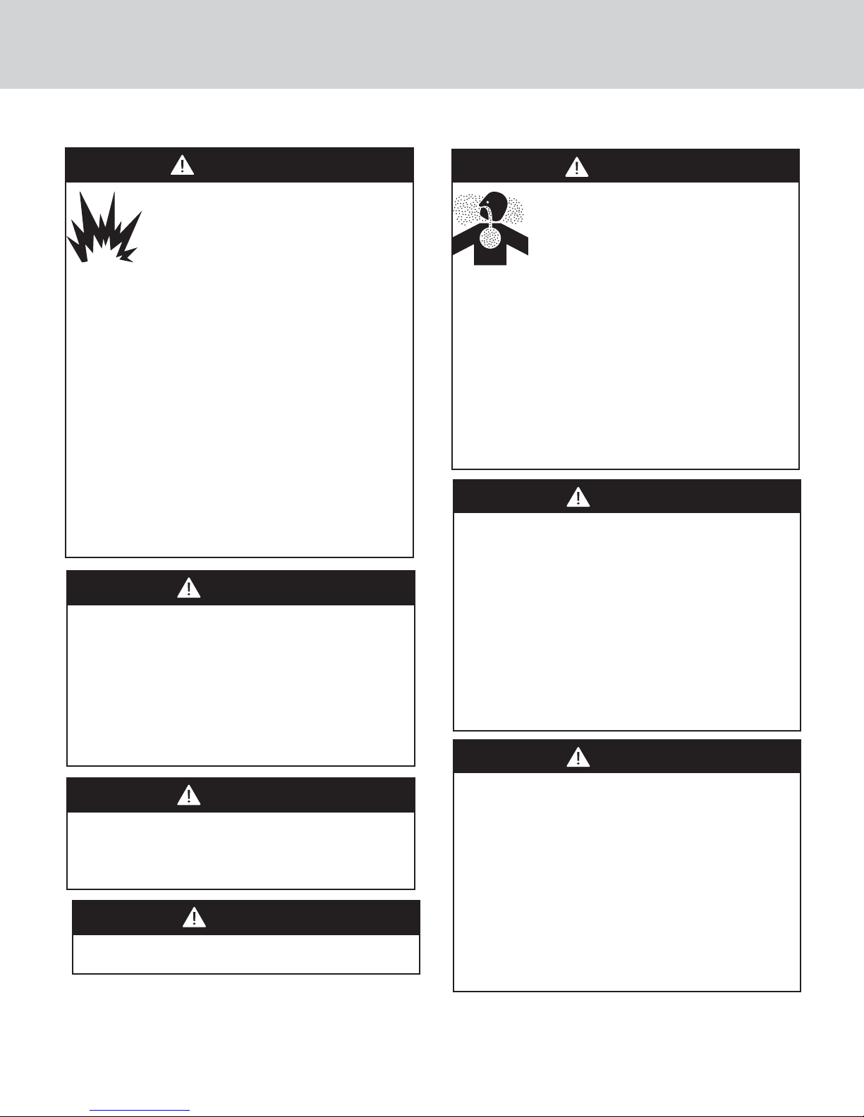
FIRE/EXPLOSION HAZARD
IF THE INFORMATION IN THIS MANUAL
IS NOT FOLLOWED EXACTLY, A FIRE
OR EXPLOSION MAY RESULT CAUSING
PROPERTY DAMAGE, PERSONAL INJURY,
OR DEATH.
• DO NOT store or use gasoline or other
flammable vapors and liquids in the vicinity of this
or any other appliance.
• WHAT TO DO IF YOU SMELL GAS:
–DO NOT try to light any appliance.
–DO NOT touch any electrical switch.
–DO NOT use any phone in your building.
–Immediately call your gas supplier from a
neighbor’s phone.
–Follow the gas supplier’s instructions.
–If you cannot reach your gas supplier, call the fire
department.
• Installation and service must be performed by
a qualified installer, service agency, or the gas
supplier.
BURN HAZARD
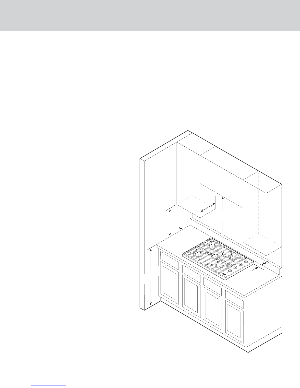
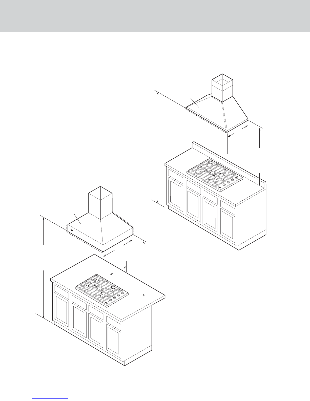
The use of cabinets for storage above the
appliance may result in a potential burn hazard.
Combustible items may ignite, metallic items may
become hot and cause burns. If a cabinet storage
is to be provided the risk can be reduced by
installing a range hood that projects horizontally
a minimum of 5” (12.7 cm) beyond the bottom of
the cabinets.
WARNING
CHEMICAL HAZARD
If not installed, operated and maintained
in accordance with the manufacturer’s
instructions, this product could expose
you to substances in fuel or from fuel
combustion which can cause death or serious
illness and which are known to cause cancer, birth
defects, or other reproductive harm.
For example, benzene is a chemical which is part
of the gas supplied to the cooking product. It
is consumed in the flame during combustion.
However exposure to a small amount of benzene
is possible if a gas leak occurs. Formaldehyde and
soot are byproducts of incomplete combustion.
Properly adjusted burners with a bluish rather than
yellow flame will minimize incomplete combustion.
CAUTION
Before placing the cooktop into operation, always
check for gas leaks with a soapy water solution
or other acceptable method. DO NOT USE AN
OPEN FLAME TO CHECK FOR LEAKS.
CAUTION
This appliance shall not be used for space heating.
This information is based on safety considerations.
WARNING
ELECTRICAL GROUNDING INSTRUCTIONS
The cooktop must be electrically grounded in
accordance with local codes. Installation should be
made by a licensed electrician. This appliance is
equipped with a three-prong grounding plug for
your protection against shock hazard and should
be plugged directly into a properly grounded
receptacle. DO NOT cut or remove the grounding
prong from the plug. For personal safety, this
appliance must be properly grounded. DO NOT
under any circumstances cut or remove the third
(ground) prong from the power plug.
WARNING
Prior to installation, ensure that the local
distribution conditions (nature of the gas and gas
pressure) and the adjustment of the appliance are
compatible. The adjustment conditions for this
appliance are stated on the label (or data plate).
This appliance is not connected to a combustion
products evacuation device. It shall be installed
and connected in accordance with current
installation regulations. Particular attention shall
be given to the relevant requirements regarding
ventilation.