Vintronics Classic 25 User manual

VINTRONICS
TM
CLASSIC 25 POWER AMPLIFIER
The Classic 25 Power Amplifier has been designed and Hand-Built in the UK.
It combines the sound proven electronic circuitry together with fine build quality and
components.
The Amplifier is constructed from the finest brushed stainless steel chassis, which
has been laser cut for precision finish. This is complemented by teak wooden side
panels varnished in a satin finish. The front and rear panels are hand engraved 1mm
thick Perspex panels finished in a dark blue ink. Brushed aluminium control knobs
compliment the finish. No question, this amplifier is of the highest design and build
standard. Heavy rubber feet act as sound absorbers to protect against microphony of
the valves. Local companies have been used to provide the parts for this amplifier.
The power amplifier is based around two pairs of EL34 (6CA7) tetrode output valves
operating in a pure Class-A push-pull output configuration.
The output transformers have been specially designed and wound to our
specifications. They have been de-rated so as to avoid core saturation at Low
frequencies. Hence this provides full frequency response right down to 20 Hertz.
Similarly, the power supply transformer has been de-rated to stop voltage sags at
peak current demands from the output amplifier stage.
This then combines to make a rugged amplifier virtually flat across the whole audio
frequency spectrum, even under complex load conditions.

The input stage has a high frequency roll-off at 30KHz so as to limit the wasted
energy in the following stages.
The input amplifier stage adopts the Double Triode ECC83 high gain valve in a
Totem pole configuration. This enables a high input impedance together with fine
linearity in frequency response. The output of this stage then feeds into a Phase
inverter stage, another ECC83 valve being used for this. Its output then feeds into the
output driver stage with an ECC82 valve being used for the purpose.
Signals from this stage are then fed into the EL34 push-pull output stage. Full power
supply voltage is applied to these valves to maximise output power.
Conversion of the high voltage signal is then done in the output transformers. They
convert the high impedance high voltage into low impedance high current drive to the
loudspeakers.
The input, phase splitter and driver valves are separately heated from the output
valves which dramatically improves the stability and noise performance.
Best quality components have been used in this amplifier.
We have utilised high tolerance quality wirewound and carbon resistors, polyester
and silver mica signal capacitors, porcelain valve bases and matched output valves.

SPECIFICATIONS
Power Output 25 Watts RMS per channel
THD at 1KHz 0.05% at 5 Watts
0.45% at 22 Watts
THD at 100Hz 0.22% at 5 Watts
0.57% at 22 Watts
Noise Better than -66dB
Crosstalk Better than -80dB
-------------------------------------------------------------------------------------------------------
Frequency Response 25 Hz to 25 KHz (-0.9dB/-0.8dB)
Power consumption 180 Watts
Loudspeaker Loads 4 Ohm, 8 Ohm
Valves 2 x ECC82
3 x ECC83
4 x EL34 (6CA7)
Input Sensitivity 0.7V RMS
Connections Inputs 4 x RCA Phono
Outputs 2 x 4mm Terminal Posts
Power IEC Mains inlet
Weight 10.3 Kilos
Dimensions 420 x 290 x 150 mm High
* TYPICAL VALUES MEASURED WITH LINDOS LA101/2 TEST SET.

+3dB
-3dB
0 10 20 30 40 50 60 70 80 90 100 200 500 1K 10K 11 12 13 14 15 16 17 18 19 20K
FREQUENCY RESPONSE

INSTALLATION GUIDE
Like all Valve Amplifiers, this Amplifier produces heat when in use.
It is therefore important that the lid of the amplifier is free to vent warm air from the
internal components. Shortened life of the components will result if overheating is
allowed to occur.
It is therefore ideal if the Amplifier is placed on it own, or the other Hi-Fi components
are placed either to the side or underneath it.
The Amplifier has two output Impedances, 4 ohm and 8 ohm. Choose the output
connection which best suits your speakers. Normally speakers are marked with their
impedance and this can be measured with an Ohm-meter. So the loudspeaker would
connect to the Black (negative) terminal and either the yellow (4Ω) or red (8Ω)
terminal. Use generous guage cable to the loudspeakers. This will aid with losses
between the amplifier output and the speaker.
The inputs to the amplifier are Gold plated Phono (RCA) sockets. There is nothing
much to say about these, other than good quality cables will reduce the risk of RFI
(radio frequency interference). Four inputs are available.

SERVICING GUIDE
It is obvious that no liquid should be allowed to get inside the box. This will result in
destruction and possible cause of fire.
Cleaning is best done with a damp cloth only.
It will be necessary to replace the valves at some point. This should be performed by
a qualified or experienced person.
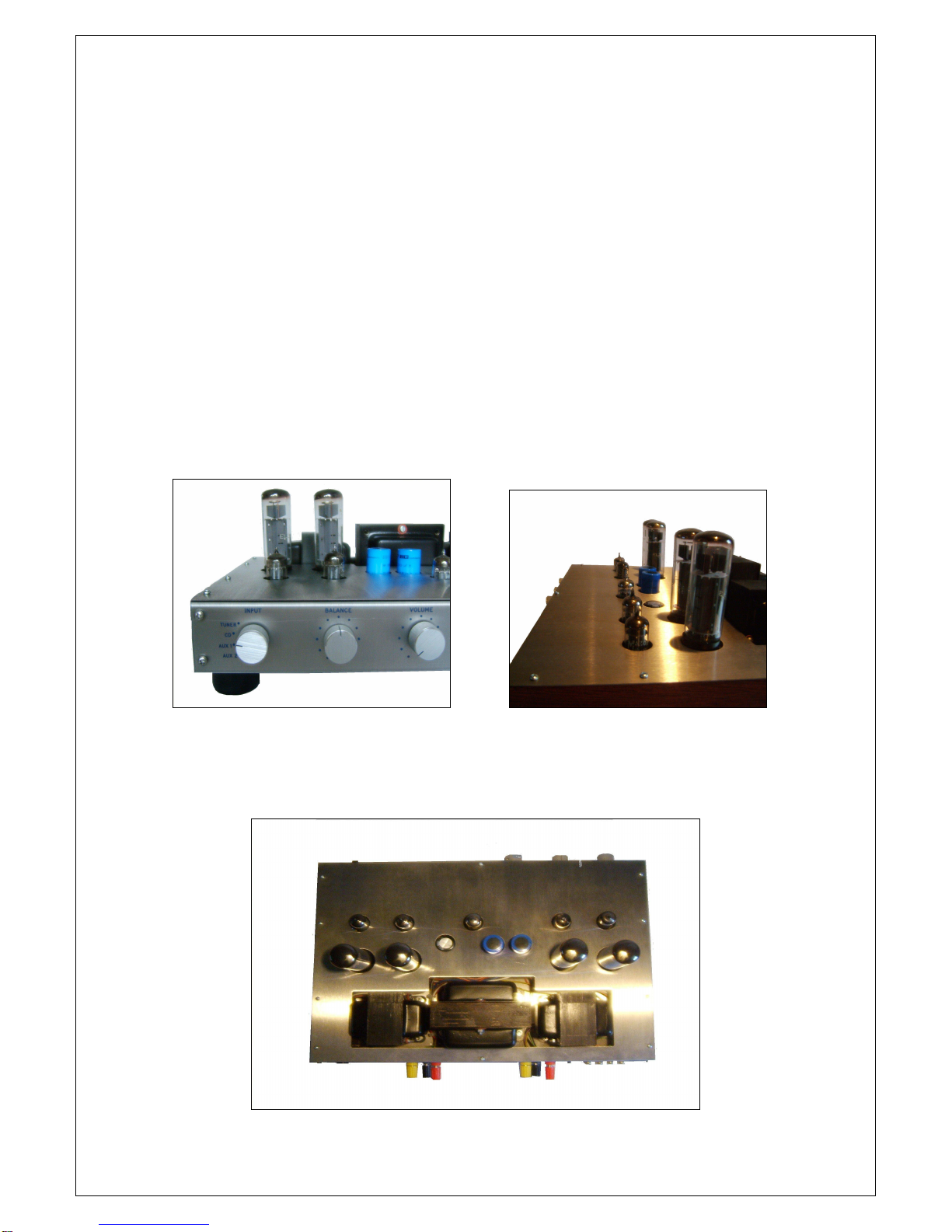
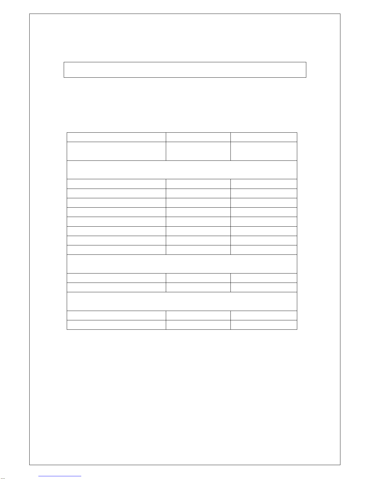
To remove the top cover, unscrew the 4 retaining screws on the top pillars of the box
and raise the lid off. The valves are easily accessible and can be removed.
There are only two adjustments inside which are pre-set. These are trimmer resistors
on each power amplifier board. These are factory preset for minimum noise and
distortion.
PLEASE NOTE WITH EXTREME CAUTION, there are DEADLY voltages inside the
amplifier. These voltages can take a few minutes to dissipate. Therefore extreme
caution is needed when changing valves. If in any doubt then leave this job to a
qualified person.
Valve types are, EL34 (6CA7) for the four output valves.
ECC83 on the input and driver stages, 3 used
ECC81 used in the driver stage, 2 used.
When replacing please try and use the highest quality manufacturer of the valves.
Limited One Year Warranty
This product is warranted to be free from defects in materials or workmanship for a
period of one year from the date of purchase by the original owner.
To ensure a high level of performance and reliability for which this equipment has
been designed and manufactured, read the user guide before operating. In the event
of failure, notify and return the defective unit to VINTRONICS or its authorised agent
as soon as possible for repair under warranty subject to the following conditions:
Conditions of Warranty
1. The equipment has been installed and operated in accordance with the
instructions in this user guide.
2. The equipment has not been subject to misuse either intended or
accidental, neglect, or alteration other than as described in the user guide
or service manual, or approved by Vintronics.
3. Any necessary adjustment, alteration or repair has been carried out by
Vintronics or its authorised agent.
4. The defective unit is to be returned carriage prepaid to Vintronics or its
authorised agent with proof of purchase.
5. Units returned should be packed carefully to avoid transit damage. The
valves are to be removed and labelled in the order of position.

Important Safety Instructions
WARNINGS –
Read the following instructions before proceeding:
Read instructions:
Retain these safety and operating instructions for future reference. Adhere to all
warnings printed here and on the amplifier. Follow the operating instructions printed
on this user guide.
Do not remove cover:
Operate the amplifier with its covers correctly fitted. Disconnect mains power by
unplugging the power cord if the cover needs to be removed for visual inspections
within. Also remove the power source when replacing valves. Refer this work to
competent personnel only.
Power sources:
Connect the amplifier to a mains power supply as marked on the rear of the unit
only. Use the power cord with a sealed mains plug appropriate for your local mains
supply as provided with your amplifier. If the provided plug does not fit into your
outlet consult your service agent for assistance.
Power cord routing:
Route the power cord so that it is not likely to be walked on, stretched or pinched by
items placed upon or against it.
Grounding:
Do not defeat the grounding and polarisation means of the power cord plug. Do not
remove or tamper with the ground connection in the power cord.
Water and moisture:
To reduce the risk of fire or electric shock do not expose the amplifier to rain or
moisture or use it in damp or wet conditions. Do not place containers of liquids on it
which might spill into any openings.
Ventilation:
Do not obstruct the ventilation slots or position the amplifier where the air flow
required for ventilation is impeded. If the amplifier is to be operated in a rack unit or
flightcase ensure that it is constructed to allow adequate ventilation.
Heat and vibration:
Do not locate the amplifier in a place subject to excessive heat or direct sunlight as
this could be a fire hazard. Locate the amplifier away from any equipment which
produces heat or causes excessive vibration.
Servicing:
Switch off the equipment and unplug the power cord immediately if it is exposed to
moisture, spilled liquid, objects fallen into the openings, the power cord or plug
become damaged, during lightening storms, or if smoke, odour or noise is noticed.
Refer servicing to qualified technical personnel only.
Installation:
Install the amplifier in accordance with the instructions printed in this user guide. Do
not connect the output of power amplifiers directly to the inputs of the amplifier. Use
audio connectors and plugs only for their intended purposes.
RISK OF ELECTRIC SHOCK
DO NOT OPEN
CAUTION
ATTENTION: RISQUE DE CHOC ELECTRIQUE – NE PAS OUVRIR
WARNING: This equipment must be earthed

CLASSIC 25 Serial No.
LEFT RIGHT
NOISE FLOOR CCIR
WEIGHTED
RESPONSE MEASURED AT OUTPUT TERMINALS AT
10 WATTS RMS OUTPUT INTO 8 OHM LOAD.
30Hz
100Hz
400Hz
1KHz
6KHz
10KHz
15KHz
20KHz
DISTORTION MEASURED AT 10 WATTS OUTPUT INTO
8 OHM LOAD.
1KHz
100Hz
CROSSTALK MEASURED AT 10 WATTS OUTPUT INTO
8 OHM LOAD.
1KHz
10KHz

CLASSIC 25
Line-up Procedure.
The Amplifier will need the Output Valves replacing after many thousands of hours
use. Usually the valves will eventually decline with age and this is the point when the
valves need replacing.
For best performance it is best to obtain matched-pair valves as replacement.
To replace the valves, simply remove the old valves by pulling the vales out of their
sockets and replacing with new valves by lining up the pip on the valve with the
socket. Usually twisting the valves around lightly in the socket until they engage with
the pip is acceptable.
The valve is then pushed home into the socket carefully.
FOR EXPERIENCED QUALIFIED PERSONS ONLY.
If you have the necessary test equipment, then remove the top plate from the
Amplifier to expose the circuitry.
EXTREME CAUTION is required as there are FATAL VOLTAGES within the
Amplifier unit.
Adjust the trimmer resistor R with a trimmer tool to obtain true linearity of a
sinusoidal waveform as measured on the Loudspeaker terminals whilst connected
into an 8 ohm dummy load.
This is best done by applying a 1 KHz sine wave to the amplifier input and increasing
the input level until the amplifier goes into clipping.
At this point adjust R to obtain balanced clipping on the peaks.
Adjustment for balanced waveform.

VOLTAGE MEASUREMENTS ON THE CLASSIC 25
1 Voltage Tolerances should be within +/- 15% of those stated below.
2 All voltages are DC with respect to Ground unless otherwise stated.
TEST
POINT
VOLTS DC VOLTAGES FOR 25 VOLTS PK-PK AT 8 OHM AT
1KHZ SINE WAVE
TP1 220 3.5V PK - PK
TP2 1.8
TP3 3.5
TP4 120 3.5V PK - PK
TP5 4.4
TP6 4.4
TP7 108 35V PK - PK
TP8 108 35V PK - PK
TP9 22 15Mv ripple at 100Hz ( no signal)
TP10 22 15Mv ripple at 100Hz ( no signal)
TP11 337 350V PK – PK
TP12 337 350V PK – PK
TP13 338 150V PK - PK
TP14 338 150V PK - PK
TP15 283 Negligible ripple
TP16 308 10mV Ripple @ 100Hz
TP17 339 800mV Ripple @ 100Hz
TP18 9.45
TP19 3.2 AC VOLTAGE
TP20 3.2 AC VOLTAGE
TP21 3.2 AC VOLTAGE
TP22 3.2 AC VOLTAGE
TP23 350
Table of contents