Elsys SGA-2 User manual

User Manual
SGA2
Strain Gauge Amplifier
SGA2 Boxed
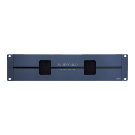
SGA2 Rack

2 Elsys AGSGA2 User Guide
Contact Information
Elsys AG
Mellingerstrasse 12
CH-5443 Niederrohrdorf
Switzerland
+41 (0) 56 496 01 55
www.elsys-instruments.com
Legal Notice
TranAX® is a registered trademark by Elsys AG
TraNET® is a registered trademark by Elsys AG
Thank you!
Thank you for purchasing Elsys Strain Gauge
Measurement Equipment.
For more information, please visit
www.elsys-instruments.com
Notice
The information in this document is subject to
change without notice.
ELSYS AG SHALL NOT BE LIABLE FOR
TECHNICAL OR EDITORIAL ERRORS OR
OMISSIONS CONTAINED HEREIN; NOR FOR
INCIDENTAL OR CONSEQUENTIAL DAM-
AGES RESULTING FROM THE FURNISHING,
PERFORMANCE, OR USE OF THIS MATERIAL
Safety Information
This instrument is intended for indoor use and
should be operated in a clean, dry environ-
ment. Do not block any ventilation openings.
Make sure this product‘s operating environ-
ment is kept within the parameters as specified
in the chapter Operating Condition!
The design of the instrument has been verified
to conform to the EN 61010-1 safety standard
per the following limits:
• Installation (Over voltage)
• Category II (Main Supply Connector) and
Category I (Measuring Terminals)
• Pollution Degree 2
• Protection Class I
Warning (Rack Unit only)
Lethal voltages exist inside the instrument.
Only qualified technicians of supplier sta are
authorized to open the case of the Base Unit.
Otherwise warranty will be lost!
Always ensure that power cord is removed
before opening the case.

3Elsys AG SGA2 User Guide
Content
1. Introduction............................................................ 4
1.1 Overview ...........................................................................4
1.2 Key Capabilities...........................................................4
1.3 Operating Elements..................................................5
2. Connections ......................................................... 6
2.1 Connector and Cable...............................................6
2.2 Pin Assignment ..........................................................6
3. Operating Modes .................................................7
3.1 Basics .................................................................................7
3.2 Full Bridge......................................................................7
3.4 Quarter Bridge.............................................................8
3.3 Half Bridge.....................................................................8
4. Configuration........................................................ 9
4.1 Hardware Settings .....................................................9
4.2 Quarter Bridge Resistor R4.................................9
4.3 Software Settings....................................................10
5. Calculations.......................................................... 11
5.1 Quarter Bridge.............................................................11
5.2 Half Bridge....................................................................11
5.3 Full Bridge (Load Cell)..........................................11
6. Open the SGA Box Enclosure.......................12
7. Base Unit Specifications..................................13
7.1 Mechanical Specification .....................................13
7.2 Power...............................................................................13
8. SGA2-Box MK2 ...................................................13
8.1 Mechanical Specification ....................................13
8.2 Power ..............................................................................13
9. Amplifier Specifications ..................................14

4 Elsys AGSGA2 User Guide
1. Introduction
1.1 Overview
The Strain Gauge Amplifier SGA-2 MK2 is
designed as a dierential front-end amplifier
to connect full, half or ¼ bridge strain gauges
with internal bridge completion.
The amplifier is available as a 2-channel boxed
version or as a multi-channel rack system.
Typical Applications:
• Deformation testing for material
characterization
• High speed dynamic material deformation
• Load Cell measurements
1.2 Key Capabilities
• Internal ½- and ¼ bridge completion
• Two independent channels per module
• Gain x1, x10, x100
• 4-wire and 6-wire technique
• 1.5 MHz bandwidth at gain x1, x10
• Low oset voltage drift
• Low output noise
• Auto-Oset compensation
• USB or RS485 interface for configuring all
settings and read back of the actual output
signal.
• Dierent input connector variant available
(6-Pin, 7-Pin and 16-Pin)
2-Channel Boxed Variant
• 2-Channel modules SGA-Box/6,
SGA-Box/7 or SGA-Box/16
• USB interface (emulated COM port)
• External power supply
Multi-Channel Rack Version
• 2-Channel Rack-Modules SGA-Box/6,
SGA-P/7 or SGA-P/16
• Amp-BU-10
(for up to 5 modules / 10 channels)
• Amp-BU-24
(for up to 12 modules / 24 channels)
• USB interface (emulated COM port) for
accessing all installed amplifier (Internally
over RS485)

5Elsys AG SGA2 User Guide
Bridge Connector
1 / 10 / 100
Gain Switch
Zero/ Auto Oset Status LED
Analog Output
1.3 Operating Elements
The following illustrations show the operating
elements of the SGA in the boxed version.
Ext. Trigger Input
for Auto Oset
USB Interface Earth
12 V Power Supply

6 Elsys AGSGA2 User Guide
2. Connections
2.1 Connector and Cable
The SGA cable assembly with LEMO circular
push pull connectors, straight plug male with
cable collet. CLAD72 defines the maximum
outer cable diameter, e.g. 7.2mm.
Connector Type Lemo part Number
6 pin Lemo FGG.1B.306.CLAD72
7 pin Lemo FGG.1B.307.CLAD72
16 pin Lemo FGG.2B.316.CLAD72
Recommended cable for 7 pin connectors:
Data cable, shielded 4x2x0.25 mm², bare cop-
per, stranded wire.
E.g.: VOLLTRON-TWIST-CY 4X2X0,25mm²,
VOLLAND
6-Pin 7-Pin 16-Pin Color1) Signal
3
6
1
6
1
4
White
Brown
+Vex
-Vex
2
5
2
5
3
2
Green
Yellow
+Sense
-Sense
4
1
3
4
5
6
Grey
Pink
+Vin
-Vin
- 7 9 Blue ¼ Bridge
2.2 Pin Assignment
1) Applies to cables manufactured by Elsys only.
Lemo 6-Pol
3
2
4
1
5
6
Lemo 7-Pol
Lemo 16-Pol
1
3
5
6
2
4
8
9
7
10
16
1
2
3
4
5
6
7
RG R2
R3R4
Connector
Case
1
2
34
5
6
7
2
16
1514
13
12
11
10
1
3
4
567
8
9
1
2
34
5
6
Solder cup view of male connector

7Elsys AG SGA2 User Guide
3. Operating Modes
3.1 Basics
The amplifier can be used for quarter, half or
full bridge strain gauges. Depending on the
sensor type, the bridge must be completed
inside or outside the amplifier to create a full
bridge.
For long cables, we recommend using 6-wire
wiring to compensate for the voltage drop
across the cables. With 6-wire, the voltage is
regulated directly at the sensor and not in the
amplifier itself.
1
2
34
5
6
7
2
16
1514
13
12
11
10
1
3
4
567
8
9
Lemo 7-Pol
Lemo 16-Pol
1
3
5
6
2
4
8
9
7
10
16
1
2
3
4
5
6
7
RG R2
R3R4
Connector
Case
1
2
34
5
6
7
2
16
1514
13
12
11
10
1
3
4
567
8
9
Lemo 7-Pol
Lemo 16-Pol
1
3
5
6
2
4
8
9
7
10
16
1
2
3
4
5
6
7
RG R2
R3R4
Connector
Case
6-Wire Full Bridge 4-Wire Full Bridge
Sensor Int. Half Bridge Int. Quarter Bridge R4
Full Bridge Disabled not assembled
Half Bridge Enabled not assembled
Quarter
Bridge
Enabled assembled
3.2 Full Bridge
The complete bridge is formed outside the
amplifier.

8 Elsys AGSGA2 User Guide
1
2
34
5
6
7
2
16
1514
13
12
11
10
1
3
4
567
8
9
1
3
5
6
2
4
8
9
7
10
16
1
2
3
4
5
6
7
RG
R4
Connector
Case
Lemo 7-Pol
Lemo 16-Pol
1
2
34
5
6
7
2
16
1514
13
12
11
10
1
3
4
567
8
9
1
3
5
6
2
4
8
9
7
10
16
1
2
3
4
5
6
7
RG
R4
Connector
Case
Lemo 7-Pol
Lemo 16-Pol
6-Wire Half Bridge 4-Wire Half Bridge
3.3 Half Bridge
Half of the bridge is formed internally in the
amplifier. The external bridge is formed by one
or two active sensor elements.
3.4 Quarter Bridge
The Quarter Bridge consists externally only
of the active sensor element. To complete the
bridge, the resistor R4 must be fitted internally
to match the sensor element.
Temperature Compensation
Strain Gauge sensors are very sensible on
temperature changes. For compensating the
change in resistance due the temperature
change, a second strain gauge sensor can be
used as completion resistor R4. This “dummy”
sensor must be mounted as close as possible
to the active sensor Rg but must not follow the
deformation of the device under test. Even if
two sensors are used, it is still a quarter bridge
as only one sensor is active.
1
2
34
5
6
7
2
16
1514
13
12
11
10
1
3
4
567
8
9
1
3
5
6
2
4
8
9
7
10
16
1
2
3
4
5
6
7
RG
Connector
Case
Lemo 7-Pol
Lemo 16-Pol
Quarter Bridge

9Elsys AG SGA2 User Guide
4. Configuration
Each SGA module can be configured by its on-
board dip-switches or with the free available
SGA 2.0 configuration software. The software
is available on the website under
www.elsys-instruments.com
4.1 Hardware Settings
Hardware configuration is straight forward and
(except for gain) individually configurable for
both channels.
Independent gain selection per channel is only
available with the SGA2 configuration software.
Board Address (Rack Only)
The board address (rotary switch) has to be
selected ones for a board. In the boxed version,
this address is per default set to 0. In a rack
version with multiple boards, each device
needs a unique address.
Bridge Configuration
For each channel, there are four DIP switches
available. According to the position of these
switches, the excitation voltage will be set to
10 V or 5 V, 6-wire or 4-wire, enable internal or
external Half Bridge. The fourth DIP switch is
not used at the moment.
4.2 Quarter Bridge Resistor R4
There are two screw terminals, one for each
channel, for assembling the internal Quarter
Bridge R4 Resistor. This will be necessary in
case of using a Quarter Bridge sensor. The
resistance of R4 has to match the one of the
used sensor, eg. 120 Ω.

10 Elsys AGSGA2 User Guide
4.3 Software Settings
All hardware settings that are set via the
DIP switches can also be configured via the
software. As soon as a setting has been made
via the software, the DIP switch settings are
ignored.
To return to the hardware settings, the cor-
responding reset command must be sent via
software or the reset button on the front panel
must be pressed for at least 3 seconds.
When the software is started, all COM ports
are scanned for a connected amplifier. If an
amplifier is found, the connection is estab-
lished automatically.
Bridge Configuration
• For 6-wire measurements, enable “Use
Voltage Sense”
• Configure the amplifier as Full-Bridge or as
Half/Quarter bridge.
• If Quarter bridge is used, the internal resis-
tor R4 must be mounted.
Auto-Oset / Zero
Before the measuring bridge can be used, it
must be balanced, otherwise an oset voltage
is measured which can overdrive the amplifier.
To a certain extent, the amplifier can compen-
sate for the oset. To do this, press the “Zero”
button on the front panel or click on “Auto
Oset” in the software. The LEDs on the front
indicate whether the oset compensation was
successful.
Front LEDs
There is a two-colour LED (red and green) for
each channel.
Color Description
O Output signal outside ± 100mV
Green Output signal within ± 100mV
Red Error during Zero compensation
Orange Error during Zero compensation, currently
gain settings within ± 100mV
Live Values
The Check box “Enable live value” returns the
measured voltage of the selected channel
according to its configuration. Please note that
the live value or the software command
GETADC returned value has a precision of
approx. 2% and is meant to see a trend or
position of a sensor or measurement. For high
speed and high resolution, the signal must be
measured on the analog output with a dedicat-
ed Transient Recorder.

11Elsys AG SGA2 User Guide
5. Calculations
5.1 Quarter Bridge
Calculating the strain from the measured
output voltage:
where
• Gamp Amplifier Gain
• Vo Output Voltage
• Vex Excitation Voltage
• GfGauge Factor
5.2 Half Bridge
5.3 Full Bridge (Load Cell)
where:
• G Amplifier Gain
• Vo Output Voltage in mV
• S Sensitivity in mV/V
• LR rated load in Kg

12 Elsys AGSGA2 User Guide
6. Open the SGA Box Enclosure
In case of changing the Dip-Switch settings,
the SGA boxed version has to be opened.
Please note that all settings can be done with
the Elsys SGA 2.0 Tool.
Necessary tools:
T8 Torx or star screwdriver
Remove the connector for external calibration
on the rear side.
Loose and remove the two Torx screws using
a T8 Torx or star screwdriver.
Pull gently on the BNC connectors to get the
Board out of its housing.
Be careful; don’t pull o the earthing cable
connect-ed to the rear side.

13Elsys AG SGA2 User Guide
7. Base Unit Specifications
7.1 Mechanical Specification
Product Type Mechanical Dimensions Max. Nr. of Modules
Amp-BU24 19“-Rack Case approx. 480x290x140 mm up to 24 channels, 12 modules
Amp-BU10 Desktop Case approx. 250x290x140 mm up to 10 channels, 5 modules
7. 2 Power
Main Power Voltage
100 to 250 VAC, 50/60 Hz
Power consumption
max. 75 W
Inlet Protection Fuse
Type 5x20 mm, only T2AL fuses must be used.
There are two fuses installed.
8. SGA2-Box MK2
8.1 Mechanical Specification
Case
Aluminum case
Approx. 110x45x185 mm (WxHxD)
8.2 Power
12 VDC, max. 700mA
by a Mains Adapter
100 to 240 VAC, 50/60Hz

14 Elsys AGSGA2 User Guide
9. Amplifier Specifications
Configurable Modes
6-wire, 4-wire, Full Bridge,
½ Bridge, ¼ Bridge
Gain
x1, x10, x100
Indication of adjusted Bridge
Front-LED
Input stage
Dierential Amplifier
Bandwidth
1.5 MHz (G=1, 10)
600 kHz (G=100)
Input Impedance
2 x 1 MΩ II approx. 25 pF to GND
Input Bias Current
< ±60 nA
Oset Voltage (Referred to Output)
< ±2.5mV, Note *1)
Oset Voltage Drift (Referred to Output)
< ± (30 + 1 * Gain) µV/°C, Note *1)
Gain Error
< ±0.1 % (G= 1, 10), < ±0.5 % (G=100)
Slew Rate (10 - 90 %)
< 300ns (Gain=1, 10)
< 700ns (Gain=100)
Note: *1) after 1h Warm-Up Time at Tamb = 25°C
and auto zero
Output Noise Int. ½ Bridge O Int. ½ Bridge On
Bandwidth Bandwidth
Gain 100 kHz Full 100 kHz Full
x 1 0.03 mVrms
0.3 mVpp
0.3 mVrms
2.0 mVpp
0.05 mVrms
0.8 mVpp
0.4 mVrms
6 mVpp
x 10 0.08 mVrms
0.6 mVpp
0.5 mVrms
5 mVpp
0.3 mVrms
2.5 mVpp
2.5 mVrms
40 mVpp
x 100 0.6 mVrms
4 mVpp
1.5 mVrms
15 mVpp
3 mVrms
20 mVpp
20 mVrms
150 mVpp
Noise performance is measured without USB connection. Detach or disconnect USB during the measurement!
Output Impedance
50 Ω +/-1%
Output Voltage Swing
max. ±5 V (no Load)
max. ±2 V (Load = 50 Ω)
Input Voltage (Protected Input Range)
max. ±42 V (Signal Inputs)
max. ±5 V (Excitation Voltage Pins)
Excitation Voltage
10 V (±5V) or 5 V (±2.5V), ±0.1%
Excitation Voltage Load
max. 90 mA
Internal ½ Bridge Asymmetry
max. ±0.1% (= 10 mV @ 10V)

15Elsys AG SGA2 User Guide
Power Supply
12 Vdc ±10%, max. 5 W per 2 Ch
Operating Temperature
0 to 45 °C
Storage Temperature
-20 to 60 °C
Relative Humidity
< 80 % (up to 31 °C)
decreasing to < 50% at 31 to 45°C
Operating Elevation
max. 2’000 m
Connector Type Output
BNC
Connector Type Input
Lemo 16-Pol. Model FGG.2B.316.xx
Lemo 7-Pol. Model FGG.1B.307.xx
Lemo 6-Pol. Model FGG.1B.307.xx
File Revision:
Date Description
09.11. 2023 Manual Update

16 Elsys AGSGA2 User Guide
EU Declaration of Conformity
Declaration Number: 231113
The Manufacturer: Elsys AG
Mellingerstrasse 12
5443 Niederrohrdorf
Switzerland
Declare that the product: SGA2 Box | SGA2 Rack
2 to 24 channel strain gauge amplifier device
is conformal to the following directives and standards:
Product Standards: IEC 61326-1:2020 (ed.3.0)
CISPR 11:2015 class B
CISPR 11:2015/AMD1:2016 class B
CISPR 11:2015/AMD2:2019 class B
CISPR 32:2015 class B
CISPR 32:2015/AMD1:2019 class B
Basic Standards: EN 61000-3-2:2019
IEC 61000-3-2:2018/AMD1:2020
EN 61000-3-3:2013+AMD:2019
IEC 61000-3-3:2013
IEC 61000-3-3:2013/AMD1:2017
IEC 61000-3-3:2013/AMD2:2021
EN 61000-4-2:2009
IEC 61000-4-2:2008
EN 61000-4-3:2020
IEC 61000-4-3:2020
EN 61000-4-4:2012
IEC 61000-4-4:2012
EN 61000-4-5:2014+A1:2017
IEC 61000-4-5:2014
IEC 61000-4-5:2014/AMD1:2017
EN 61000-4-6:2014IEC 61000-4-6:2013 (ed 4.0)
EN 61000-4-8:2010
IEC 61000-4-8:2009
EN 61000-4-11:2020
IEC 61000-4-11:2020
This declaration of conformity is issued under the exclusive responsibility of the
manufacturer.
Niederrohrdorf, 13.11.2023 Elsys AG
Roman Bertschi
Other manuals for SGA-2
1
Table of contents
Other Elsys Amplifier manuals

