manuals.online logo
Brands
  1. Home
  2. •
  3. Brands
  4. •
  5. Carver
  6. •
  7. Amplifier
  8. •
  9. Carver CM-2002 User manual

Carver CM-2002 User manual

CM 2002
CM 2002
CM 2002
CM 2002
CM 2002 CM 2002
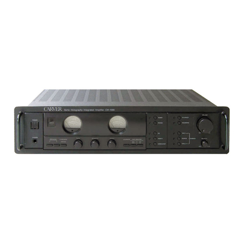
Integrated Amplifier
with Sonic
Holography
--- - ---=
..0= :::: .. __ .__
",
-
13. Damage Requiring Service - The Component
should be serviced only by qualified service personnel
when:
A. The power-supply cord or plug has been damaged;
or
B. Objects have fallen, or liquid has spilled into the
Component; or
C. The Component has been exposed to rain; or
D. The Component does not appear to operate normally
or exhibits a marked change in performance; or
E. The Component has been dropped, or its cabinet
damaged.
14. Servicing - The user should not attempt to service
the Component. All servicing should be referred to
qualified service personnel.
15. Power Lines - An outdoor antenna should be
located away from power lines.
16. To prevent electric shock, do not use this polarized
plug with an extension cord, receptacle or other outlet
unless the blades can be fully inserted to prevent blade
exposure.
Pour preevenir les chocs electrlques ne pas utiliser
cette fiche polarisee avec un prolongateur, un prise de
courant ou une autre sortie de courant, sauf si les lames
peuvent etre inserees
fond sans laisser aucune pariie
decouvert.
17. Grounding or Polarization - Precautions should
be taken so that the grounding or polarization means of
the Component is not defeated.
18. Internal/External Voltage Selectors - Internal or
external line voltage selector switches, if any, should
only be reset and re-equipped with a proper plug for
alternate voltage by a qualified service technician. See
an Authorized Carver Dealer for more information.
Chapter _
e
Safety nstructions
1. Read Instructions -- All the safety and operation
instructions should be read before the CM-2002 is
operated.
2. Retain Instructions - The safety and operating
instructions should be kept for future reference.
3. Heed Warnings - All warnings on the Component
and in these operating instructions should be followed.
4. Follow Instructions - All operating and other
instructions should be followed.
5. Water and Moisture - The Component should not be
used near water - for example, near a bathtub, washbowl,
kitchen sink, laundry tub, in a wet basement, or near a
swimming pool, etc.
6. Ventilation - The Component should be situated so
that its location or position does not interfere with its
proper ventilation. For example, the Component should
not be situated on a bed, sofa, rug, or similar surface that
may block any ventilation openings; or placed in a built-
in installation such as a bookcase or cabinet that may
impede the flow of air through ventilation openings.
7. Heat - The Component should be situated away from
heat sources such as radiators, or other devices which
produce heat.
8. Power Sources - The Component should be con-
nected to a power supply only of the type described in
these operation instructions or as marked on the Compo-
nent.
9. Power Cord Protection - Power-supply cords should
be routed so that they are not likely to be walked upon or
pinched by items placed upon or against them, paying
particular attention to cords at plugs, convenience
receptacles, and the point where they exit the Component.
10. Cleaning - The Component should be cleaned only
as recommended in this manual on Page 7.
11. Non-use Periods-The power cord of the Component
should be unplugged from the outlet when unused for a
long period of time.
12. Object and Liquid Entry - Care should be taken so
that objects do not fall into and liquids are not spilled into
the inside of the Component.
19. Attachment Plugs for Alternate Line Voltage
(Dual voltage models only) - See your Authorized
Carver Dealer for information on the attachment plug for
alternate voltage use. This pertains to dual-voltage units
only.
ATTENTION --This apparatus does not exceed the
Class NClass B (whichever is applicable) limits for
radio noise emissions from digital apparatus as set out in
the radio interference regulations of the Canadian
Department of Communications.
ATTENTION - Le present appareil numerique n'emet
pas de bruits radioelectriques depassant las limites
applicables aux appareils numeriques de class Nde class
B (selon le cas) prescrites dans le reglement sur le
brouillage radioelectrique edicte par les ministere des
communications du Canada.
Chanter 1
CAUTION: TO REDUCE THE RISK OF ELECTRIC SHOCK
DO NOT REMOVE COVER OR BACK)
NO USER-SERVICEABLE PARTS INSIDE
REFER SERVICING TO QUALIFIED SERVICE PERSONNEL
&
CAUTION
&
L
RISK OF ELECTRIC SHOCK
DO NOT OPEN •
&
The lightning flash with arrowhead symbol
within an equilateral triangle is intended to alert
the user to the presence of uninsulated
dangerous voltage within the product's
enclosure, that may be of sufficient magnitude
to constitute a risk of electric shock to persons.
/1
&
The exclamation point within an equilateral
triangle is intended to alert the user of the
presence of important operating and main-
tenance (servicing) instructions in the literature
accompanying the appliance.
PORTABLE CART WARNING
Carts and stands - The
Component should be used
only with a cart or stand
that is recommended by
the manufacturer.
A Component and cart
combination should be
moved with care. Quick
stops, excessive force, and
uneven surfaces may cause
the Component and cart
combination to overturn.
WARNING - TO REDUCE THE RISK OF FIRE OR ELECTRIC SHOCK,
DO NOT EXPOSE THIS APPLIANCE TO RAIN OR MOISTURE.
CAUTION: TO PREVENT ELECTRIC SHOCK, MATCH WIDE BLADE
OF PLUG TO WIDE SLOT, FULLY INSERT.
ATTENTION: POUR EVITER LES CHOCS ELECTRIQUES, INTRO-
DUIRE LA LAME LA PLUS LARGE DE LA FICHE DANS LA BORNE
CORRESPONDANTE DE LA PRISE ET POUSSER JUSQU AU FOND.
Chapter 1
<11II ; »
Contents
Chapter 1: Introduction
Page
Safety instructions 2, 3
Introduction 4
Features and specifications 5
Unpacking and paperwork 6
Handle removal. 6
Location and Connections 7
Chapter 2: Rear panel
This shows you how to hook up
all of your components.
Input/output levels 8
Turntable and tape decks 9
CD, Tuner and Auxiliary 10
External processor 11
External amplifier 11
Speaker connections 12
Speaker placement 13
Chapter 3: Front panel
This is the main guide to the
front panel and remote control.
Front panel controls 14-15
The Power Meters 16
The remote control 17
Recording 18
Appendices
A
B.
e.
D.
Sonic Holography
Connection cables
Troubleshooting
Service assistance
19
20
21,22
23
Introduction
As an American electronics innovator for
over fifteen years, Carver Corporation has
contributed some of the industry's most
impressive and remarkable audio
technologies. In fact, many features that are
now considered standard (surround sound
and advanced signal processing) had their
first successful consumer applications in
Carver products. Today, many of our
components are regarded as Classics , still
used by their original owners.
Our continuing goal is to provide
affordable products of exceptional quality,
aimed at reproducing sound with absolute
accuracy. We are best known for our separate
audio components (particularly high-
performance power amplifiers), therefore,
any integrated amplifier bearing the Carver
name has extremely high standards to meet.
Combining the latest in signal path
technology with the muscle of Carver
amplification, the CM-2002 stands high
above its class. The amplifier section has the
performance and the clarity of some of the
best separate designs. The preamplifier
section includes essential purist features to
impress both the CD and the Record
collector. It has a separate digital input with
integral D/A converter and the phono
section accepts either Moving Magnet or
Moving Coil cartridges.
The CM-2002 also features Carver's
exclusive Sonic Hologram processing for
lifelike sound field imaging. There are
connections which allow the addition of an
external processor or equalizer and another
connection for adding an external amplifier.
These features allow great flexibility when
upgrading your system to higher power or
surround sound.
Thank you for placing your confidence in
us. We know that your integrated amplifier
will provide you with many years of listening
enjoyment.
Please make sure that you read the
Safety Instructions on page 2 and 3
and the unpacking and location
details on page 6 and 7.
_ Chapterl
Features
-<
r ,
• Sonic Holography enhances the
three dimensional imaging
• Inputs for CD, Tuner, Auxillary and
two Tape decks
• Phono input for turntables with
Moving-Magnet or Moving-Coil cartridges
• One coaxial Digital input and
internal
DI
A converter
• Two Tape record outputs
• External processor loop
• Preamplifier outputs allow the addition of
an external amplifier
• Remote control
• Independent recording of any input,
including dubbing between decks.
• Motorized volume control
• Bass and Treble controls
• Loudness
• Mute control
• Headphone jack
• Two illuminated power meters
• Solid mechanical construction with
exceptional finish and styling
• The handles can be removed to make the
CM-2002 17 inches wide
• AC outlets
• Available in 120 V or 240 V versions
50 60
Hz
Specifications
Power Output:
105 watts per channel
( continuous power into 8 ohms)
THD :
<
0.08
%
at full power
Separation:
>
70 dB
@
1
KHz
Frequency response:
20 Hz - 20 kHz,
( +
0 dB, - 1 dB )
Signal to Noise ratio:
>
98 dB
(relative to full power, A weighted)
Input sensitivity:
CD, Tuner, Aux, Tape: 160 mV
MC 210 V, MM 2.6 mV
(for 150 mV from Tape out)
Tone control effect :
Bass:
+
8 dB
I -
8 dB
@
100 Hz
Treble:
+
8 dB
I -
8 dB
@
10 kHz
Loudness:
+
6 dB
@
100 Hz,
+
2.5 dB
@
10 kHz
Digital input format:
S PDIF
Digital Analog converter
THD :
<
0.05
@
1 kHz
SIN:
100.dB
( Aweighted, from Tape-out)
Power consumption:
62 watts at idle
190 watts at normal listening levels
457 watts at full power
Dimensions (
Depth x Height x Width) :
13.8 x 6.7 x 19 inches, with handles
(350 x 170 x 483 mm )
13.5 _x 6.7 x 17 inches, without handles
(343 x 170 x 432 mm )
Net Weight:
23 lbs.
Shipping Weight:
281bs.
lOA
kg)
(12.7kg)
e
I
The specifications are subject to change
without notice.
V{
HI
CO
h
t;v
If
Y
V
e
'11
,-j-
or--
Handle Removal
Chapter 1
llElli»
e
Unpacking
Carefully unpack your CM-2002 and keep
the original carton and packing materials for
future moving shipment or long-term
storage. Make sure that you save the two end
caps which come in the box. These are used
if you do not want the handles fitted.
The CM-2002 and the accessories should
reach you in perfect condition. If you notice
any shipping damage please contact your
Carver Dealer immediately.
Important Paperwork
You should save your sales receipt and
keep it in a safe place. This is required if you
ever need to obtain warranty service.
Write down the serial number which is
located on the back of the CM-2002 and
record it in the space provided below.
Please take a moment to fill out the
customer response card and return it to
Carver. This provides us with important
information from our valued customers.
There is also a section for you to note any
comments you may have about our products.
Model: CM-2002
The CM-2002 comes with the handles
installed. If you do not want them they can
be replaced with the two supplied end caps
as follows:
1. Unplug the power cord.
2. Remove the three Phillips screws on
each side of the chassis as shown
below.
3. Pull out the handle assembly and
install the spacers provided.
4. Reinstall the three screws on each side
of the chassis to secure the end caps
in place.
s.
Store the handles in a safe place for
future use.
Remove
Handles
Serial Number: _
Purchased at:
Install
End caps
Date:
ccessories
The following are supplied with the
CM-2002 :
Remote control and batteries
This owners manual
Warranty description sheet
Consumer response card
Two end caps to use if the handles
are removed.
_ Chapter 1
Location
Observe the following precautions when
choosing a location for the CM-ZOOZ:
• Do not expose the unit to rain or
moisture.
• Protect from prolonged exposure to
direct sunlight.
• Avoid exposure to extreme cold or dust.
• Protect from heat and allow adequate
ventilation. Place away from any direct
sources of heat such as heating vents and
radiators. Make sure that air is allowed to
circulate freely behind, beside and above
the unit. Excessive heat is a common
cause of component failure.
• Do not place heavy objects on top of the
CM-ZOOZ.
• Do not place any audio or VCR tapes or
computer disks near the CM-ZOOZ.They
may be erased by the magnetic fields of
the transformer.
• Avoid exposure to electrostatic discharge.
..
• If you ever accidently spill anything on
the CM-ZOOZ,unplug the power cord and
contact your dealer for service
information.
l
are
You can gently dust off the front panel
and chassis with a soft dry cloth. Try to rub
horizontally, following the grained finish of
the front panel. Take extra care when
cleaning the window, not to leave any
scratch marks.
If you have something stubborn to
remove, use a mild dish soap or detergent
sparingly applied to a soft cloth. Do not use
alcohol, ammonia, or other strong solvents.
onnections
• No special tools are required to set up
your system, just RCA patch cords and
the speaker wires.
• Make sure that all of your components
are OFF before making or undoing any
connections.
• Connections labeled out on the source
component connect to those on the
CM-ZOOZthat are labeled in . For
example, the output from a CD player
connects to the CM-ZOOZCD input.
• The CM-ZOOZTape 1 and Tape Z outputs
connect to the record inputs of your tape
decks.
• Make sure that you connect left to left and
right to right. For example, the left output
from your CD player should connect to .
the left input of the CM-ZOOZ.
• It will help if you tag and identify each
connection cord and speaker wire.
• Whenever possible, keep the power cords
away from the patch cords and speaker
wires. This will reduce the chance of
picking up any electrical interference.
• The CM-ZOOZhas some AC outlets on the
rear panel. These should only be used for
low power components such as CD
players and tape decks .
• You might consider buying a good
quality surge suppressor to protect your
system from power spikes and surges.
• Always turn on the CM-ZOOZafter all the
other components are on.
• When turning off your system, always
turn off the CM-ZOOZfirst. This
precaution will reduce any turn-on or
turn-off noises in the speakers.
o
Chapter 2
<iB£ Z :»
Chapter 2 RearPanel connections
The following pages contain drawings of typical connections that you might make in your
installation. These drawings demonstrate how each of the inputs and outputs on the rear panel
of the CM-2002 are interconnected with other audio components and speakers.
Your particular installation may not use all of the connections shown, although, if you are
using the CM-2002 as the center of a fully-fledged audio system you will use many or most of
them.
The inputs and outputs on the CM-2002 are labeled to correspond to the most common audio
and video components in use today. It is perfectly acceptable to connect other components to
unused inputs or outputs, so long as they have line level signals. The phono input must only be
used for a turntable.
Input/ output levels
Input and output levels for audio equipment are usually divided into three categories:
1 Phono Level
This is a very low level signal
that comes from the cartridge
of your turntable. Because of
its extremely low voltage, the
CM-2002 has a special phono
input designed
on y
for
turntables. The phono circuit
provides extra gain to
increase the signal, as well as
RIAAre-equalization to
restore the flat frequency
response. This is altered by
the equalization used in
making phonograph
recordings. A Moving-Coil
cartridge has a much lower
output than a Moving-
Magnet type. The CM-2002
rear panel switch will
increase the gain when using
the Moving-Coil type.
o
2 LineLevel
This is the signal level that
comes out of almost all audio
components produced today,
except for power amplifiers,
turntables and microphones.
It ranges from several
hundred millivolts to several
volts (AC). Any line level
signal can be connected to
any of the line level inputs on
the CM-2002. For example, if
you have a DATtape deck,
but you don't have a second
cassette deck, you can
connect it to the TAPE2
input. A VCR can also be
connected to a Tape input for
playback and recording. A
LaserDisc player can be
connected to the Auxillary
input.
3 Speakerlevel
This is the signal level that
comes out of the speaker
output terminals on the
CM-2002. It can range from a
low level up to 30 volts (AC).
Some high-powered
amplifiers can reach voltage
levels approaching that
present on a household AC
outlet These connections
should only be made to a
speaker.
""
Chanter 2
Turntable and Tape decks
..i
,
Any standard turntable with either a Moving-Magnet or Moving-Coil cartridge can be
connected to the phono inputs of the CM-2002. The turntable must have a phono-level output,
not line level. Make sure the CM-2002 is off before setting the cartridge selector switch.
Connect the ground wire of the turntable to the ground connector on the CM-2002 to reduce
any hum heard in the speakers.
Moving
Magnet
e
Do not use the
MC
position unless you
are sure that your
cartridge has a
Moving Coil
Cartridge
Moving
Coil
Cartridge Selector
left and right
outputs
SPEAKERS
m
EXT.PAOC
OUT IN
PRE MAIN
OUT IN
LEFT
0_
RIGHTO_
•
L
R
The Tape players can be any standard
component with a line level output, such as a
cassette deck, reel to reel or DAT.
The connections allow the playback of the tape
and recording.
Youcan also connect a VCRto listen to movie
sound tracks or make good quality audio recordings.
The VCR'saudio inputs and outputs would connect in
exactly the same way as the tape deck shown. The
video or RFoutput connects to your TVset.
_MC MM
TAPE
IN
CD TUNERAUX 1 2
TAPE
OUT
1 2
IIH
The ACoutlets
can supply
power to your
source
components
but are not
recommended
for amplifiers.
,
I
Play
outputs Record
inputs Record
inputs
I
I
II
IBI 18
; ; g90
e
=- ....
oo
[gJ' •••••
ii ••
. .-J.
Chapter 2
< I£I »
CD Tuner and Auxillary connections
These inputs can connect to any standard audio component as long as they have a line-level
audio output. These include CD players, Tuners, TV, DAT, Video games, Laser Disc, VCR, DVD,
DSS and computers.
If your component has a digital output, then you can connect it to the coaxial digital input.
To select this component, press the CM-2002
CD input selector on the front panel.
To select the digital input, you would lso
press the CM-2002 Digital-CD-input button.
00
11
m
11_[
c:::n=
c=EC:l
00000000
audio digital
outputs output
(!)
SPEAKERS
m
•
L
R
LEFT
00
sxr.sacc
our
PRE
MAIN
ccr
RIGHT_O
-
•
outputs
outputs
•
FM 90 7
: [II
111--
To select this, press the CM-2002
Tuner input selector. To select this, press the CM-2002
AUX input selector.
e
Chanter 2
External Processor connections
An external processor can be connected by first pulling out the two D-shaped jumpers in the
external processor loop on the rear panel. Components which can be connected include surround
processors, equalizers and electronic crossovers. The output from the CM-2002 goes into your
processor and the processed or equalized output then goes back into the CM-2002.
Remove External
Processor Jumpers
Pull out these two jumpers
I•
, •• , ;;. if-
=> ••
RIGHT ••
@)
@)
-
@)
@ @ @ @ @ @ @
@ @ @ @ @ @ @
External
processor
•
outputs
::
1. Turn off the CM-2002.
2. Pull out the two jumpers.
3. Connect the output to
the input of your processor.
4. Connect the input to the
output of your processor. .
External mplifier connections
An external amplifier can be connected by pulling out the two Pre-out/Main-in jumpers. This
will disconnect the internal amplifier section of the CM-2002. There will be no sound from the
speakers or headphones, only the external amplifier and its speakers will receive a signal. The
CM-2002 will just act as a preamplifier.
The Pre-out is the end of the preamplifier section and the Main-in is the start of the internal
amplifier section.
Pull out these two jumpers , •
0
@)
<i>
if(
I I
@)
-
.;
I I
@ @ @ @ @ @ @
@)@)@)@)@)@)@)
Amplifier
R
inputs
SPE KERS
m
LEFT ••
RIGHT ••
•
Remove Pre-out/
Main-in jumpers
::
1. Turn off the CM-2002.
2. Pull out the two jumpers.
3. Connect the Pre-out to
the input of your amplifier.
4. You can leave the Main-in
disconnected.
,.,--
Chapter 2 _
e
SpeakerConnections
The CM-2002 output terminals are designed to accept
bare speaker wires.
1) Strip 1/2" of insulation off each wire and make sure to
carefully twist all the fine strands together. Even if
one strand is loose and touches the opposite terminal,
a short circuit will result.
2) Unscrew the CM-2002 terminals and insert the wire.
Tighten the connection down onto the wire
( finger tight only) .
@
@)
-
•
>
1-1-1-1
D
1
@
( )@@( )( )( )( )
@ @ @ @ @ @
Take great care to connect the red
output posts of the CM-2002 to the
red posts of the speakers.
Also connect the black CM-2002
posts to the black speaker posts.
\
\
\
1\
i
))
\
!
j
I
: I
\\ \
\\
\
1 \ \
J \
I
!
J
i
1(:)
I
i
,
I i
\
;
\.\
This will keep all the
speakers "in phase". For
example, if there is a
loud drum beat, all the
speaker cones will be
moving outwards at the
same time. If one speaker
is "out of phase" then its
speaker cone will move
inwards at this time.
This causes a sound
cancellation, resulting in
a bass reduction.
\ \ \ \ I
\II/it
x-"""'lt1ir\
\
\
\
\
\
'\
, : ,Ji,i)
! ;\
+
1
.. . Chapter 2
Speaker lacement
Eg Ja diStance
Since there are many different speaker designs available, you should closely follow the
recommendations of your speaker manufacturer, with the addition of the following points.
t
1. Adjust the toe-in so that they both
point in towards the listening chair.
2. To get the best results from the Sonic
Hologram circuit, the left speaker should be
set exactly the same distance away from your
listening position as the right speaker. While
this relationship is important in any stereo
system, it is more important when using the
Sonic Hologram. It might help to place a
coin as a marker, on the center of the chair.
Measure from this point to the center of each
speaker and adjust until they are the same
distance away.
3. Ideally, the speakers should be no closer
than two feet from the rear and side walls, in
order to reduce any reflections that might
upset the Sonic Hologram imaging. If your
speakers are closer than this, you can
experiment by adding sound deadening
material, such as curtains, on the walls to
reduce any unwanted reflections. For more
details of the Sonic Hologram, see page 19.
==== ====== ------------
Chapter 3 Front Panel features
Chapter 3 __
e
Cf\RVER
CM-2002 Integrated Amplifier
<9 <9
Tape1 Tape2
( ,.4.,,_."·, ,
<9
CD
Gl
Aux
WATTS
0.010.1 1 1030100 200
\\\\iIIMj)'
POWER OUTPUT
WATTS
cot
0.1 1 1030100 200
\\\\iIIMjl
POWER OUTPUT
Tuner Phono
(9 (9
Hologram
e
DAC
eON
Volume
IR
window
•• Digital CD input
0'
Treble Balance Loudness Record
Out Source
direct
Speaker
Mute
Bass
@
Power Headphones
(9 (9
Tape 1 Tape 2
.iiiiht%
(9
CD
(9
Aux These input selector buttons allow you to choose which source
you would like to listen to. The indicator lights will show which
source is currently selected.
Tuner Phono
G G
This will engage the Hologram circuit to improve the three dimensional
imaging, giving a more accurate sense of the position of the various
musicians and special effects. See Page 19 for more details.
Hologram
G
DAC
G
on
Digital CD input
This will select the Digital Input as your listening source. The Digital sign
from your CD, DVD or LaserDisc will be converted by the internal D/A
converter.
Make sure that you also press the CM 2002
CD
input selector or th
will be no sound.
The Volume can be adjusted manually or by using the remote control. It .
motorized, so be careful not to hold it or impede its movement when us'
the remote. Make sure the volume is turned down before turning on the
CM-2002.
Volume
G
POWER
HEADPHONES
SPEAKER
MUTE
BASS
TREBLE
BALANCE
,-
LOUDNESS
RECORD OUT
SOURCE DIRECT
_ Chapter 3
This is the main power switch to turn the CM-2002 on or off. When this is
pressed the standby light above it will turn on and your system will be ready to
play after a few seconds. You may hear the relays click on during this start-up
time.
This accepts a standard 1/4 inch stereo headphone plug. It does not shut of the
main speakers when the headphones are plugged in. Usethe Speaker-Mute
control if you want headphone-only listening.
Use this to temporarily turn off the sound to your speakers. It does not affect the
headphones or your recordings.
This control will boost or reduce the output level in the Bass frequency range.
Turning it fully clockwise will provide a boost of 8 dB
@
100 Hz.
Turning it fully counterclockwise will produce a reduction of 8 dB
@
100 Hz.
This control will boost or reduce the output level in the Treble frequency range.
Turning it fully clockwise will provide a boost of 8 dB
@
10 kHz.
Turning it fully counterclockwise will produce a reduction of 8 dB
@
10 kHz.
This is used to balance the output of your speakers. It is useful if you are sitting
closer to one speaker than the other.
Turn it clockwise to make the left speaker play quieter.
Turn it counterclockwise to make the right speaker quieter.
If you are listening with the Sonic Hologram engaged you should set the
balance to the center position.
This will improve the performance when listening at lower volume levels by
boosting both the Bass output and the Treble at the same time.
It provides a 6 dB boost at 100 Hz and a 2.5 dB boost at 10 kHz.
This allows you to select which sound source you would like to record onto
your Tape decks. Rotate this control until the desired source is selected and then
set your Tape decks to record. You can listen to something else at the same
time. See page 18 for some recording examples.
This will bypass the Tone controls and the Balance.
The signal path is shorter and this will improve the sound quality.
Chapter 3 _
Power eters
WATTS
0.01 0.1 1 10 30100 200
-40 -30 -20 -10 -5 0 +3
'\\\\\IIIIIPP/
POWER OUTPUT
The eM-2002 features ballistically-
weighted power meters that are calibrated in
decibels. The main dB scale has a top value
of +3dB, with OdBequal 100 watts per
channel into 8 ohms.
The meter ballistics include a fixed
amount of overshoot, the needles can move
past the OdBlevel when played loud.
On some musical material, the amplifier
could be reaching its maximum power even
though the meters aren't reaching full scale.
Operation
The front panel power button will turn
the eM-2002 ON or OFF.
$ When this is pushed in, the
I!!...
standby light will flash for a
p""""
few seconds until the eM-2002
OWE:R
is ready for use.
Gl
When it is pushed out, the
eM-2002 is OFF,and it will not
respond to the remote control.
Then, the only way to turn it
ON is by pushing the button in
again.
--
If the eM-2002 is ON and you use the
remote control power button to turn it OFF,
it will go into the standby mode. There will
be no power to the speakers and all the lights
will go out except for the standby light. The
eM-2002 will respond to the remote control
power button to turn it back on again.
POWER OUTPUT
WATTS
0.01 0.1 1 10 30100 200
-40 -30 -20 -10 -5 0 +3
\\\\IIIIIPP/
This is because the meters are indicating the
ver ge
power output. Momentary musical
peaks can drive the amplifier to its
maximum output for brief periods, faster
than the meter needles can respond.
The best way to tell whether the amplifier
is overloading is to listen. If the sound
becomes distorted on musical peaks at the
same time the meter needles are pegging ,
you have probably exhausted the eM-2002's
power reserves. If this occurs, you should
reduce the volume level.
A typical listening session would be as
follows:
1. Turn on vour Cl), Tape decks, etc.
2. Turn down the volume control and push
the front panel power button in.
3. Play your Cl), Tape, etc and adjust the
volume as desired.
4. When finished, you can use the remote
control to turn off the eM-2002, by
putting it into standby.
5. The Standby light will stay on, indicating
that it is ready to be turned on at any
time.
6. If you have finished listening for the day,
you should press the front panel power
switch to turn it off. This is a precaution
in case of power surges during the night.
_ Chapter 3
Remote Control
POWER This turns the CM-2002 ON or into its standby mode.
If the CM-2002 is already on, it 'will go into standby when this button is pressed.
It can be turned on by pressing this again.
l
v •
MUTE This turns off the audio output to the speakers
and the headphones. The standby light will blink
when this is engaged. It does not affect the record
outputs.
INPUT These allow you to select the source you
SELECTORS would like to hear. They do not affect the
record selection
-=--===-:-
Volume UP
The remote is powered by two supplied
"AAA"batteries.
These Volume controls will rotate the
motorized volume knob on the front panel
Volume DOWN
CD player These will only work with players which follow
controls the RC-S remote control standard.
-
-
=!J
Range
20
feet
1/',""
..
..
"
: :
::: : :
This is the general
operating range of
he remote control
r:r-
Chapter 3 _
Recording
The Record-out selector on the front panel
of the CM-2002 will allow you to select the
source you would like to record on either
tape deck. You can record something
different from that playing in your speakers.
Recording from one Tape deck
to another Tape dubbing).
When you have selected a record source,
there will be an output from the CM-2002
TAPE lout and TAPE 2 out on the rear panel.
This is a straight copy of whichever source is
selected and it is unaffected by the Tone
control settings, the Sonic Hologram, Mute
or the Volume controls.
The Record-out selector will allow you to
record from Tape 1 to Tape 2 or from Tape 2
to Tape 1.
For example, if you want to record from
Tape 1 to Tape 2 :
1. Rotate the Record-out selector to the
position marked Tape
lc-Z.
Recording audio components.
T'P'Ch::,, :T"""
A
The Tape deck connections are shown on
Page 9. The CM-2002 Tape outputs connect
to the inputs of your Tape deck. These inputs
are often labeled as record inputs. RECORD OUT
For an example, if you would like to
record a CD onto your Tape deck:
T'P'C
ho
"'
CD Tuner Aux
2. Press the CM-2002 Tape 1 input
selector if you want to hear the tape in
your speakers while you are recording.
3. Play your source tape in Tape deck 1.
4. The Tape deck 2 can now record the
audio from Tape deck 1
1. Rotate the CM-2002 Record-out selector
until it is selecting the CD player.
RECORD OUT
2. Press the CM-2002 CD input selector and
play the CD in your system.
3. If you wanted to record a CD using the
digital input, make sure that the CM-2002
Digital CD input is also selected.
4. Follow the instructions in your Tape deck
owner's manual to adjust the levels
correctly and then make your recording. If
your Tape deck also has microphone
inputs, make sure the Tape deck is set to the
line level record inputs, rather than the
microphone inputs.
/
e
5. When your recording is complete, you
can play it back by pressing the CM-2002
TAPE 1 or TAPE 2 input selector.
:ill
_ Appendices
Appendix A Sonic Holography
Sonic Holography is a unique process
which enhances the three-dimensional
effects and realism of stereo sound.
To understand the benefits of this circuit,
we must first understand a problem in
obtaining accurate sound reproduction.
In a stereo system, both ears hear the output
from both speakers. The left ear hears sound
from the left speaker and from the right
speaker. To see the problem with this,
compare what happens when listening to a
live musical performance:
During a concert, each ear will receive
one direct sound arrival. For example, a
cymbal crashes, both ears will hear it and our
brain tells us accurately the position of the
musician.
In a stereo recording of the concert, this
cymbal crash will be heard from both
speakers. Our left ear will hear the left
speaker, which is fine, but it will also hear
the crash from the right speaker. The extra
arrival tends to confuse our accurate sense of
positioning, giving a general feeling that the
musician might be over there somewhere .
An example of this effect is if you use a
good pair of headphones. The stereo effect is
more pronounced because the left ear only
hears the left headphone, and the right ear
hears only the right headphone with no
extra arrivals.
:}
.
\
To summarize:
1.
A real musical event will create only two
direct sound arrivals
one at the left ear and
one at the right.
rJ -
2. Stereo playback will give four arrivals
as
both speakers are heard by each ear.
These second sound arrivals reduce our
naturally accurate sense of positioning, used
for listening pleasure and self preservation.
The Sonic Hologram circuit was designed
to cancel out the unwanted second arrivals.
The left ear will mainly hear the left speaker
and the right ear mainly hears the right
speaker.
This is accomplished by sending a
complex crosstalk signal from the left and
right speakers, in addition to the normal
program. These extra signals are virtually
identical to the unwanted second sound
arrivals but they are out-of-phase with them
and they cancel each other out.
The result is a more three-dimensional
and wider soundstage, where the positioning
clues are restored. In a way, the musicians
have been freed from the confines of the flat
plane between the speakers. You will perceive
them as playing forward or playing behind
the speakers or to one side or the other, not
just somewhere in between.
We recommend that you experiment
with its effect, remember that you are
listening for a more accurate sense of the
location of the different musicians.
As the Hologram works by phase
cancellation of the unwanted second sound
arrivals, accurate speaker positioning is
required to make sure that the left speaker is
the same distance away from you as the right
speaker. You must follow the speaker
placement on Page
13
to get the best results.
This is the same as any standard stereo
system only with more care taken to position
the speakers accurately.
Sonic Holography is a registered trademark of Carver Corporation.
r== ----------------------------------------------------------
Appendices .
Appendix
B
Connections
Interconnects Speakercables
• Choose reliable hook-up cables, also
called patch cords or RCA cables. There
are many different grades of cable
available and you might want to ask
your Carver dealer for advice. The main
thing is that they should be fully
shielded and as short as possible for the
job. Try to layout the system so that
most patch cords are less than six feet,
perhaps most will be three or four feet
long.
• The longer the distance from the amplifier
to the speakers, the thicker the speaker
wire should be.
• The thickness of speaker wire is specified
as a "gauge". The thicker the wire, the
smaller the gauge. For example, 16 gauge
is thicker than 18 gauge. Most systems
use 16, 14 or 12 gauge wire.
• The following table shows the minimum
recommend gauge for different lengths.
• Some patch cords can be a very tight fit
and there is usually a preferred method
of getting them off, some have to be
removed with a twisting action. Be
gentle or you may damage the jacks of
the preamp or your other components.
• Some special patch cords can only be
hooked up in one direction, these are
usually marked with arrows.
Length Gauge
up to 2S feet 16
up to 40 feet 14
up to 60 feet 12
• For video connections, use cords made
especially for video signals, otherwise
the picture quality may be degraded.
Video cables are specially designed to
match the video circuits electrical
characteristics.
• Use speaker cables which are marked in
some way to help you connect them up
correctly. Some have a black stripe or a
ridge on one of the cables, other types
have a silver strand or thread running
through.
• It is usual for the right patch cord plugs
to be red and the left connections to be
white, grey or black. Video connections
are usually yellow.
• You might start with standard speaker
wires and connection cords and then
upgrade them later when you want to
fine tune your system. Your dealer can
advise you on the different cables and
cords available.
f

Other Carver Amplifier manuals

Carver pm1400 User manual

Carver

Carver pm1400 User manual

Carver px1450 User manual

Carver

Carver px1450 User manual

Carver PM-350 User manual

Carver

Carver PM-350 User manual

Carver A-500X User manual

Carver

Carver A-500X User manual

Carver Xi1850 User manual

Carver

Carver Xi1850 User manual

Carver M-400t User manual

Carver

Carver M-400t User manual

Carver KMOS 4200 User manual

Carver

Carver KMOS 4200 User manual

Carver M-1.5 User manual

Carver

Carver M-1.5 User manual

Carver PM-350 User manual

Carver

Carver PM-350 User manual

Carver M240 User manual

Carver

Carver M240 User manual

Carver C-1 User manual

Carver

Carver C-1 User manual

Carver MSMP User manual

Carver

Carver MSMP User manual

Carver PM-300 User manual

Carver

Carver PM-300 User manual

Carver PM-350 User manual

Carver

Carver PM-350 User manual

Carver pm125 User manual

Carver

Carver pm125 User manual

Carver M400 User manual

Carver

Carver M400 User manual

Carver CT-29v User manual

Carver

Carver CT-29v User manual

Carver ZR500 User manual

Carver

Carver ZR500 User manual

Carver MA202R User manual

Carver

Carver MA202R User manual

Carver pm1400 User manual

Carver

Carver pm1400 User manual

Carver M400 Operating manual

Carver

Carver M400 Operating manual

Carver PM-300 User manual

Carver

Carver PM-300 User manual

Carver Professional pt1250 User manual

Carver

Carver Professional pt1250 User manual

Carver M-500 User manual

Carver

Carver M-500 User manual

Popular Amplifier manuals by other brands

Midas PRO SERIES quick start guide

Midas

Midas PRO SERIES quick start guide

T+A MP 8 owner's manual

T+A

T+A MP 8 owner's manual

Niles SI-2125 Specification sheet

Niles

Niles SI-2125 Specification sheet

RDL STICK-ON ST-DA3 manual

RDL

RDL STICK-ON ST-DA3 manual

Marshall Amplification MG10 owner's manual

Marshall Amplification

Marshall Amplification MG10 owner's manual

NAD C 372 Service manual

NAD

NAD C 372 Service manual

DAPAudio DM-1000 user manual

DAPAudio

DAPAudio DM-1000 user manual

QSC CMX 300Va user manual

QSC

QSC CMX 300Va user manual

Rotel RC-850 owner's manual

Rotel

Rotel RC-850 owner's manual

Lanzar OPTI 1200HC owner's manual

Lanzar

Lanzar OPTI 1200HC owner's manual

Fosi Audio BOX X3 user manual

Fosi Audio

Fosi Audio BOX X3 user manual

Harman Kardon CITATION 17S owner's manual

Harman Kardon

Harman Kardon CITATION 17S owner's manual

Krell Industries Power Amplifier KSA  150 / 250 owner's manual

Krell Industries

Krell Industries Power Amplifier KSA 150 / 250 owner's manual

Tyco Electronics M/A-Com 19D902797G3 Maintenance manual

Tyco Electronics

Tyco Electronics M/A-Com 19D902797G3 Maintenance manual

Tangent AMP-200 Service manual

Tangent

Tangent AMP-200 Service manual

Scott 255S operating manual

Scott

Scott 255S operating manual

Harman Kardon MELODY II A-120 Operation and service instructions

Harman Kardon

Harman Kardon MELODY II A-120 Operation and service instructions

Rotel RA-612 owner's manual

Rotel

Rotel RA-612 owner's manual

manuals.online logo
manuals.online logoBrands
  • About & Mission
  • Contact us
  • Privacy Policy
  • Terms and Conditions

Copyright 2025 Manuals.Online. All Rights Reserved.