Vip2 VK2-1080VRD3V9 User manual

VK2-1080VRD(IR)3V9(F)
Installation Guide

2

3
1. Description
This manual applies to the VK2-1080VRDIR3V9F, VK2-1080VRD3V9F and VK2-1080VRD3V9
These domes are fully featured Vandal resistant day/night IP cameras
Model Name
Features
VK2-1080VRD3V9
Varifocal Lens
No IR LED
VK2-1080VRD3V9F
Motorized Varifocal Lens
No IR LED
VK2-1080VRDIR3V9F
Motorized Varifocal Lens
Built-in 24 IR LEDs
• Installation Steps
Follow these steps to install the network camera on your local network (LAN):
1. Check the package contents against the list below.
2. Connect the Network Camera.
3. Set an IP address.
4. Set the password.
• Package Component
The system comes with the following components:
• Contents in the installation CD
1. The DOMEUser’s Manual
2. The SmartManager User’s Manual
3. The VIP2 Client User’s Manual
4. The SmartManager Installation software
5. The VIP2 Installation software
Note:Check your package to make sure that you received the complete system, including all
components shown above.

4
2. Installation
2.1 Base Installation
1. Position the supplied template in the mounting location, use this template to drill the
required mounting holes and cable access holes
NOTE
The total mass of the main unit is approx 1.3kg. Check whether the ceiling to which the
Dome Camera is installed is strong enough to hold the unit mass. If not, either mount in a
different position or strengthen the ceiling.
2. Attach safety wire for securing the dome camera to ceiling or structure.
3. Insert each cable through the cable hole, connect BNC cable and communication lines.
4. Unlock (4x) torx screws on the dome cover and fix the dome case firmly with supplied
mounting screws (4x), plastic anchors (4x), O-Rings (4x).
5. Adjust desired focus and scene by turning and moving the hemisphere by hand.
6. Replace the housing cover and secure with the torx screws (4x).
As a minimum the dome requires the connection of a network cable, if a PoE switch is used this cable
can supply power as well as transmit the video. If a PoE switch is not available then a separate power
supply is required
Important note:
The O-Rings(4X) form the
primary waterproofing seal, and
must be included in the
installation process

5
2.2 cabling
Connection Cable
NO
Connector Name
Description
1
Black
Ethernet, RJ-45 port compatible with 10/100Mbps having PoE
functionality. Modular Jack
2
Red: AC24V/DC12V
White: AC24V/GND
Main Power, 3pin terminal, DC12V 470mA(4.0W) /
AC24V 5200mA(6.5W) with heater Off
3
Orange: AC24V
Black: AC24V
Heater Power, 3pin terminal, max. 25Watt @ AC24V
4
Pink: GND
Gray: Alarm Input
Brown: GND
Yellow: Alarm Out
Alarm Input and Output, 4pin terminal.
5
RCA Gray
Audio line output, RCA Jack
6
RCA Black
Audio line input, RCA Jack
Micro SD memory slot on the Board
Card Slot for Micro SD memory: Socket “J15”
• Connecting to the RJ-45
Connect a standard RJ-45 cable to the network port of the network camera. Generally a
cross-over cable is used for directly connection to PC, while a direct cable is used for connection
to a hub.
You can also use a router featuring PoE (Power over Ethernet) to supply power to the camera.
• Connecting Alarms
AI(Alarm In) :
You can use external devices to signal the dome to react on events. Mechanical or electrical
switches can be wired to the AI (Alarm In) and G (Ground) connectors.
G(Ground) :
Connect the ground side of the alarm input and/or alarm output to the G (Ground) connector.
Alarm Out :
The network camera can activate external devices such as buzzers or lights. Connect the device
to the AO (Alarm Out) and G (Ground) connectors.
• Connecting the Power (If PoE is not being used)

6
Connect the power of DC12V or AC24V for the network camera. Connect the positive(+) pole to
the ‘+’ position and the negative(-) pole to the ‘-‘ position for the DC power.
Be careful not to reverse the polarity when you connect the power cable.
You can also use a router featuring PoE (Power over Ethernet) to supply power to the
camera.
The heater will operate properly only by the heater power source of AC 24V.
If using PoE, the heater will not operate at all.
Use an adaptor if the installation site requires heater operations. Adaptor is sold separately.
For the power specifications, refer to the “Appendix”of User’s Manual. (page 75)
If PoE and DC 12V are both applied, this camera will get supplied with power from PoE.
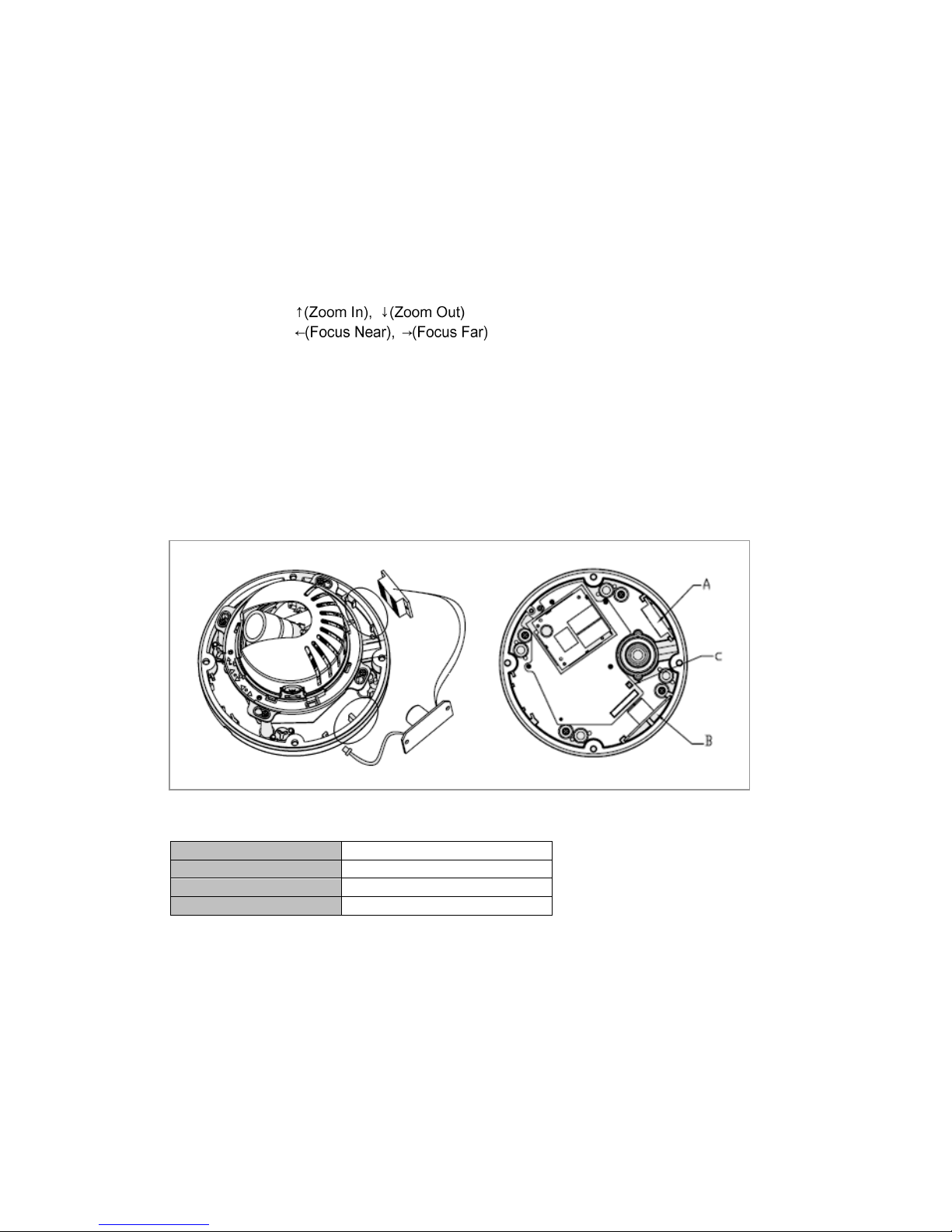
• Connecting Service Monitor Port (using VK2-LCT)
Service monitor output port (J3) is located on the board of the dome camera, and is used for an
easy OSD setup.
▶ID & IP assignment
The VK2-LCT local commissioning tool is used for an easy OSD setup. To make changes in the
OSD menu, please use the OSD controller, this is an optional purchase. You can set Camera Title
and IP Address, using a standard analogue set up monitor such as the VTMPRO. Instruction for
use of the VK2-LCT is supplied with the unit.
1. Connect VK2-LCT to the Service Monitor port of the network camera.
2. Connect Service Monitor and the Video Output port of the VK2-LCT.
3. Press the SET button to access main Menu.
4. Change Camera ID, and IP Address. You can change the Name or Title and IP address of the
camera. Using the buttons on the VK2-LCT, you can change the parameters.
5. Select SAVE or CANCEL to exit the Main Menu.

7
Video Output is used for an easy zoom and focus control when installing lens. Video Output is
restricted to 704x480(576) resolution.
▶Zoom & Focus Control
The camera enters Zoom and Focus control mode as soon as connecting the VK2-LCT to the
Service Monitor port.
-. Zoom Control:
-. Focus Control:
-. Smart Focus: Press and hold the SET button for 2 or more seconds. The camera readjusts
focus automatically.
Heater Kit Installation(Optional)
1. Place the heater element is slot “A”. Please ensure that the cables are facing upwards and the
heater is pointing towards the Dome.
2. Place the PCB in slot “B”. Please ensure that the PCB is facing inside of the Dome with the
connection blocks at the top.
3. Place the plug in the Socket “C”(J3) which is found on the controller board.
•Heater (IF Applicable)
Power Supply
24VAC
Power Consumption
20Watt
Heater On
at 41°F (5°C)
Heater Off
at 59°F (15°C)
Note: The Heater module does not come equipped with the camera; however can be purchased as
an option.
2.2 Network Connection and IP assignment
A standard straight network patch cable can be used to connect the camera to a switch or hub.
Generally if connecting directly to a PC a crossover cable would be used.
1. Connect the dome to the network and power up.

8
2. Start SmartManager utility found on the supplied CD (Start>All programs>SmartManager), the
main window will be displayed, after a short while any network devices connected to the network
will be displayed in the list.
3. Select the camera on the list and click right button of the mouse. You can see the pop-up menu
below.
4. Select Assign IP. You cam see a Assign IP window. Enter the required IP address.

9
3. Operation
The dome can be used with Windows operating system and browsers. The recommended browsers
are Internet Explorer, Safari, Firefox, Opera and Google Chrome with Windows.
3.1 Access from a browser
1. Start a browser (Internet Explorer).
2. Enter the IP address or host name of the dome in the Location/Address field of your browser.
3. The following page will be displayed. Click Live View or Setup to enter web page.
4. Live View
3.2. Access from the internet
Access from the internet once connected, the dome is accessible on your local network (LAN). To
access the dome from the Internet you must configure your broadband router to allow incoming data
traffic to the camera. To do this, enable the NAT-traversal feature, which will attempt to automatically
configure the router to allow access to the network camera. This is enabled from Setup > System >
Network > NAT.
For more information, please see “3.5.5 System>Network>NAT” of User’s Manual.

10
3.3 Set-up menu access
To gain access to the cameras set-up, a user
name and password must be entered. As default:
User = admin
Password = admin
It is recommended that the Administrator
password is changed immediately.
3.4 Live View Page
The live view page comes in eight screen
modes: 1920x1080, 1280x1024, 1280x720,
720x480(576), 640x480, 352x240(288) and
320x240. Users are allowed to select the
most suitable one out of those modes.
Please, adjust the mode in accordance
with your PC specifications and monitoring
purposes.
1) General controls
Live View Page Search & Playback Page Setup Page Help Page
The video drop-down list allows you to select a customized or pre-programmed
video stream on the live view page. Stream profiles are configured under Setup > Basic
Configuration > Video & Image. For more information, please see “3.5.1 Basic Configuration >
Video & Image” of User’s Manual.
The resolution drop-down list allows you to select the most suitable one
out of video resolutions to be displayed on live view page.
The protocol drop-down list allows you to select which combination of
protocols and methods to use depends on your viewing requirements, and on the properties of
your network.

11
2) Control toolbar
The live viewer toolbar is available in the web browser page only. It displays the following buttons:
The Stop button stops the video stream being played. Pressing the key again toggles the
start and stop.
The Pause button pause the video stream being played.
The Snapshot button takes a snapshot of the current image. The location where the
image is saved can be specified.
The digital zoom activates a zoom-in or zoom-out function for video image on the live
screen.
The Full Screen button causes the video image to fill the entire screen area. No other
window will be visible. Press the 'Esc' button on the computer keyboard to cancel full
screen view.
The Manual Trigger button activates a pop-up window to manually start or stop an event.
The Remote Focus button enables users to adjust focus and zoom remotely via network.
The Smart Focus button readjusts focus automatically.
3) Video and Audio Streams
The dome provides several images and video stream formats. Your requirements and the
properties of your network will determine the type you use.
The Live View page in the dome provides access to H.264, MPEG-4 and Motion JPEG video
streams, and to the list of available video streams. Other applications and clients can also access
these video streams/images directly, without going via the Live View page.
3.5 setup
This section describes how to configure the camera, and is intended for product Administrators, who
have unrestricted access to all the Setup tools; and Operators, who have access to the settings for
Basic, Live View, Video & Image, Audio, Event, and System Configuration.
You can configure the dome by clicking Setup in the top right-hand corner of the Live View page. Click
on this page to access the online help that explains the setup tools
When accessing the dome for the first time, the “Admin
Password” dialog appears. Enter your admin name and
password, set by the administrator.
Note: If the password is lost, the dome must be reset to
the factory default settings.
See “3.6 Resetting to the Factory Default Settings”.

12
4) Focus and Zoom Control
You can control Zoom and Focus in the live screen. Press the button on the left top in the live
screen to activate the Zoom & Focus control panel.
• Adjusting Zoom:
Click “–“ button to zoom out and click “+” button to zoom in.
The focus is moved slightly after adjusting zoom; adjust the
focus again, as necessary.
• Adjusting Focus:
Click “–“ button for far focus and click “+” button to near focus.
Note: Click the button in the live screen to set the focus to the optimum position.

13
3.6 Resetting to the factory default settings
To reset the dome to the original factory settings, go to the Setup>System> Maintenance web page
(described in “3.5.5 System > Maintenance”) or use the Reset button (SW1) on the board of the dome
camera, as described below:
• Using the Reset Button
Follow the instructions below to reset the Network Camera to the factory default settings using
the Reset button.
1. Power off the Camera by disconnecting the power adapter.
2. Remove the bubble.
3. Press and hold the Reset button (SW1) on the board with your finger while reconnecting
the power.
4. Keep the Reset button (SW1) pressed for about 5 seconds.
5. Release the Reset button (SW1).
6. The camera resets to factory defaults and restarts after completing the factory
reset.
7. Replace the bubble
CAUTION: When performing a Factory Reset, you will lose any settings you have saved.
3.7 More Information
For more information, please see the dome User’s Manual, which is available on the CD included in
this package.
Other manuals for VK2-1080VRD3V9
1
This manual suits for next models
2
Table of contents
Other Vip2 Security Camera manuals
Popular Security Camera manuals by other brands

Cisco
Cisco 3630 installation guide

EverFocus
EverFocus SG Series Quick installation guide

Samsung
Samsung SCO-2081R Series user manual

Speco
Speco CVC-550EX Specification sheet

Panasonic
Panasonic Super Dynamic III WV-CW484F operating instructions

Grandstream Networks
Grandstream Networks GXV 3615 Series manual