Viscount Spin-Tone 700 User manual

Edition: 1.0
User Manual - EN
Manuale Utente - IT


EN - 1
User Manual
INDEX
Important notes.....................................................................................................................................................................1
Looking after the product.....................................................................................................................................1
Connections.........................................................................................................................................................1
Notes about the manual.......................................................................................................................................1
General characteristics of Spin-Tone................................................................................................................................2
Connection and control panel ............................................................................................................................................2
Spin-Tone 700 installation...................................................................................................................................................5
Technical specifications......................................................................................................................................................6
IMPORTANT NOTES
LOOKING AFTER THE PRODUCT
•Do not apply excessive force to the instrument’s structures or the controls (buttons, connectors, etc.).
•When possible, do not place the instrument close to units which generate strong interference, such as radios,
TVs, computer videos, etc.
•Do not place the instrument close to heat sources, in damp or dusty places or in the vicinity of strong magnetic
fields.
•Do not expose the instrument to direct sunlight.
•Never insert foreign bodies inside the instrument or pour liquids of any kind into it.
•To clean the case, use only a soft brush or compressed air.
CONNECTIONS
•Before making the connections, ensure that all speakers you are using are off. This will prevent noisy or even
dangerous signal peaks. Always use good quality screened cables for connection to amplification or diffusion
systems. When disconnecting cables from sockets, always take hold of the connector and not the cable itself;
when winding cables do not knot or twist them.
•If the product is to be out of use for lengthy periods, disconnect the plug from the power socket.
•Connect the power cable to an earthed socket.
•Check that the voltage corresponds to the voltage shown on the serial number plate of the device.
•Clean periodically the power cable.
•Only use the power cable provided with the product.
•Do not place the power cable close to heat sources Do not damage the cable or bend it overmuch.
•Do not place heavy objects on the cable. Do not place the cable where it could be trampled.
NOTES ABOUT THE MANUAL
•Take good care of this manual.
•This manual is an integral part of the product. The descriptions and illustrations in this publication are not
binding.
•While the instrument’s essential characteristics remain the same, the manufacturer reserves the right to make
any modifications to parts, details or accessories considered appropriate to improve the product or for
requirements of a constructional or commercial nature, at any time and without undertaking to update this
publication immediately.
•All rights reserved; the reproduction of any part of this manual, in any form, without the manufacturer’s specific
written permission is forbidden.
•All the trademarks referred to in this manual are the property of the respective manufacturers.
•Read all the information carefully in order to obtain the best performances from your product and waste no
time.
•The codes or numbers in square brackets ([ ]) indicate the names of the controls and connectors of the device.
For example, [VOLUME] refers to the VOLUME potentiometer.

EN - 2
User Manual
GENERAL CHARACTERISTICS OF SPIN-TONE
The Spin-Tone amplifier series incorporates a hybrid system with a rotating horn in the upper part and two woofers
in the lower part specifically designed to recreate the sound of original rotary speakers.
Spin-Tone 700 (750W) represents the most powerful model in the line. With 3 amplified channels it is equipped
with 2 woofers with rotary effect simulation and a driver with a rotating horn.
Spin-Tone 400 (400W) is equipped with 3 amplified channels, a driver with rotating horn and 2 woofers coupled
with 2 tweeters, with which it is also possible to use the device as a normal static amplifier to be used with any
type of instrument.
Both models have a panel that contains the main controls for a quick speaker setup, such as adjusting the
equalizer, volumes, selecting of one of the 6 speaker response and operation presets, and all connectors.
Slow / Fast rotation speeds and Stop are selectable via the lever control of your Legend or Legend Soul connected
to the 11-pin connector, or via a foot-switch pedal or via MIDI.
The Rotary Editor application, compatible with Windows, MacOs, iOs, is also available on the website
www.viscountinstruments.com, which allows fine adjustment of the most important configuration parameters and
the Spin-Tone software update.
CONNECTION AND CONTROL PANEL
Spin-Tone 700
Spin-Tone 400

EN - 3
User Manual
1. [SENSITIVITY] selector: amplifier input sensitivity selector switch at the [11 PIN INPUT] connector, low (L
position, recommended for Legend Soul series organs) or high (Hposition, recommended for Legend series
organs).
2. [11 PIN INPUT] connector: 11-pin connector for connecting the instrument to be amplified. Furthermore,
through this connector, using the rotating speaker control you can select the speed (Fast or Slow) of the
speakers' rotation, or stop the engine (Brake).
3. [INPUTS] connectors:
- [MAIN]: unbalanced jack input to connect the audio signal of the instrument you want to amplify with a
rotary effect. With the Rotary Editor application it is also possible to choose whether or not to have the
simulation of the rotary effect in the woofers. With the organs of the Legend Soul and Legend series, the
use of this connector is recommended to amplify the Upper and Lower sections, connecting the [MAIN
L/MONO] output of the Legend Soul or [MAIN LEFT] or [MAIN RIGHT] of the Legend.
- [PEDALS] (present only on Spin-Tone 700):unbalanced jack input to connect the audio signal of the
instrument you wish to amplify without rotary effect and using woofers only. With the organs of the Legend
Soul and Legend series, the use of this connector is recommended to amplify the Pedals section,
connecting the organ’s [PEDALS] output.
- [STATIONARY] (present only on Spin-Tone 400):unbalanced jack input to connect the audio signal of
the instrument you wish to amplify without rotary effect. In the case of a monophonic source, use only the
[L/MONO] connector. With the organs of the Legend Soul and Legend series, the use of this connector
is recommended to amplify the Pedals section, connecting the organ’s [PEDALS] output.
4. [PEDALS GAIN] potentiometer (present only on Spin-Tone 700): potentiometer for adjusting the gain of the
signal input to the [PEDALS] connector. Turning the knob to "0” the signal is completely silent.
5. [OUTPUTS] connectors (present only on Spin-Tone 400): from these connectors it is possible to take out
the input signal to the [MAIN] connector (with or without rotary effect) and/or [STATIONARY], based on the
selection made in the Rotary Editor application, for the connecting of multiple amplifiers.
6. [STAT VOLUME] potentiometer (present only on Spin-Tone 400): potentiometer to adjust the volume of the
signal input to the [STATIONARY] connectors. Turning the knob to "0” the signal is completely silent.
7. EQUALIZER section.
This section includes controls for the semi-parametric equalizer for the input signal to the [MAIN] and
[PEDALS] connectors.
- [LOW] potentiometer: allows to adjust the attenuation (from 0 to -12 dB) or the amplification (from 0 to
+12 dB) of the low frequencies (lower than 200 Hz).
- [MID FREQ] potentiometer: allows to select the central frequency of intervention that is attenuated or
enhanced by the [MID GAIN] potentiometer. As reported in screen printing, the range of selectable
frequencies is 200 Hz –2 KHz.
- [MID GAIN] potentiometer: allows to adjust the attenuation (from 0 to -12 dB) or the exaltation (from 0
to +12 dB) of the signals around the frequency adjusted with the potentiometer [MID FREQ].
- [HIGH] potentiometer: allows to adjust the attenuation (from 0 to -12) or the exaltation (from 0 to +12)
of high frequencies (above 2 KHz).
8. [VOLUME] potentiometer: allows to adjust the output volume to the amplifier. Turning the knob to "0” the
signal is completely silent.
N.B.
An instrument can be connected to the [11 PIN INPUT] connector using
only a cable with an 11-pin connector (not supplied with the amplifier).
The [11 PIN INPUT] connector has the following pinout:
1: Audio +
4: Audio GND
5 - 6: common of speed switch
7: Fast
8: Slow
2 - 3 - 9 - 10 - 11: N.C.
If the connector has a different setup, an adapter should be used.
Pin 1
Pin 2 Pin 3 Pin 4
Pin 5
Pin 6
Pin 7
Pin 8
Pin 9
Pin 10
Pin 11

EN - 4
User Manual
9. [PRESET] selector: selection knob of one of the 6 Presets. The Rotary Editor allows the adjustment and
storage in real time of the operating parameters for the Presets. Rotation speeds, transition times, relative
levels and much more can be modified by the users according to their needs and stored in the Spin-Tone 700
and Spin-Tone 400 Presets.
10. [FOOT SWITCH] connector: connect here the cable from the pedal you wish to use to control the speed of
the rotating speakers. Use with:
- single switch type pedal: the Slow / Fast speeds are selected by shortly pressing the pedal, while keeping
it pressed stops the rotation (Brake).
- double switch pedal: one switch assumes the Brake / Go function, the other switch assumes the Slow /
Fast speed selection function.
11. [MIDI IN] connector: MIDI connector for connecting the instrument for speed and stop selection via MIDI
messages. In the default condition, the following Control Changes are received (in any channel):
- CC66=0: Slow speed
- CC66=127: Fast speed
- CC67=0: Brake off
- CC67=127: Brake on
- CC68=0: Brake on
- CC68=64: Slow speed
- CC68=127: Fast speed
12. [USB] connector: use this port to connect a computer or tablet to use the Rotary Editor application.
13. [SPEED] Led: Led displaying the currently selected speed:
- green: Brake
- red: Fast
- orange: Slow
14. [FACTORY RESET] button: factory reset button. To execute a Factory Reset, press and hold the button
when switching on the Spin-Tone 700 and Spin-Tone 400, using a pointed tool such as a pen or a small
screwdriver. At the end of the procedure, the [SPEED] Led will flash three times.
15. [POWER] switch: Vortex 315 switch on and off.
16. [MAINS AC-IN] socket: mains power supply socket.
N.B.
It is necessary to select the type of pedal used in the Rotary Editor application. In default conditions the use of a single
switch pedal is assumed.
N.B.
- Through the Rotary Editor application it is possible to choose which Control Changes to use for speeds and stopping
selection.
- It is also possible to use the following System Exclusive message for speed selection:
F0 41 10 00 08 12 02 00 10 3D 0x 00 F7,
X=0: Slow speed
X=1: Fast speed
N.B.
When a factory reset is performed, all changes to the parameters and functions made by the user will be definitely lost.

EN - 5
User Manual
SPIN-TONE 700 INSTALLATION
Spin-Tone 700 is made up of two modules, one (Upper) including the control panel and the rotating horn, the
other (Lower) containing the woofers. To proceed with the assembly of the system, follow the instructions below.
1. Position the module Upper 1on top of the module
Lower 2, taking care to orient the modules so that
the connectors 1A and 2A are on the same side
and to house the feet 1B of the module Upper 1in
the slots 2B present on the upper side of the
module Lower 2.
2. Connect the cable 3supplied with the amplifier into
the connectors 1A and 2A.

EN - 6
User Manual
TECHNICAL SPECIFICATIONS
SPIN-TONE 700
Type.....................................3 amplified channels (2 woofers with or without rotary effect + driver with rotating horn)
Power ..................................Woofer 300W + 300W - driver 150W
Max calculated SPL ...........127 dB
Crossover frequency.........adjustable using Rotary Editor between 800 Hz and 1,2 KHz
Subsonic filter....................Yes
Protection ...........................Compressor, short circuit, thermal
Editor Control (*)................Yes
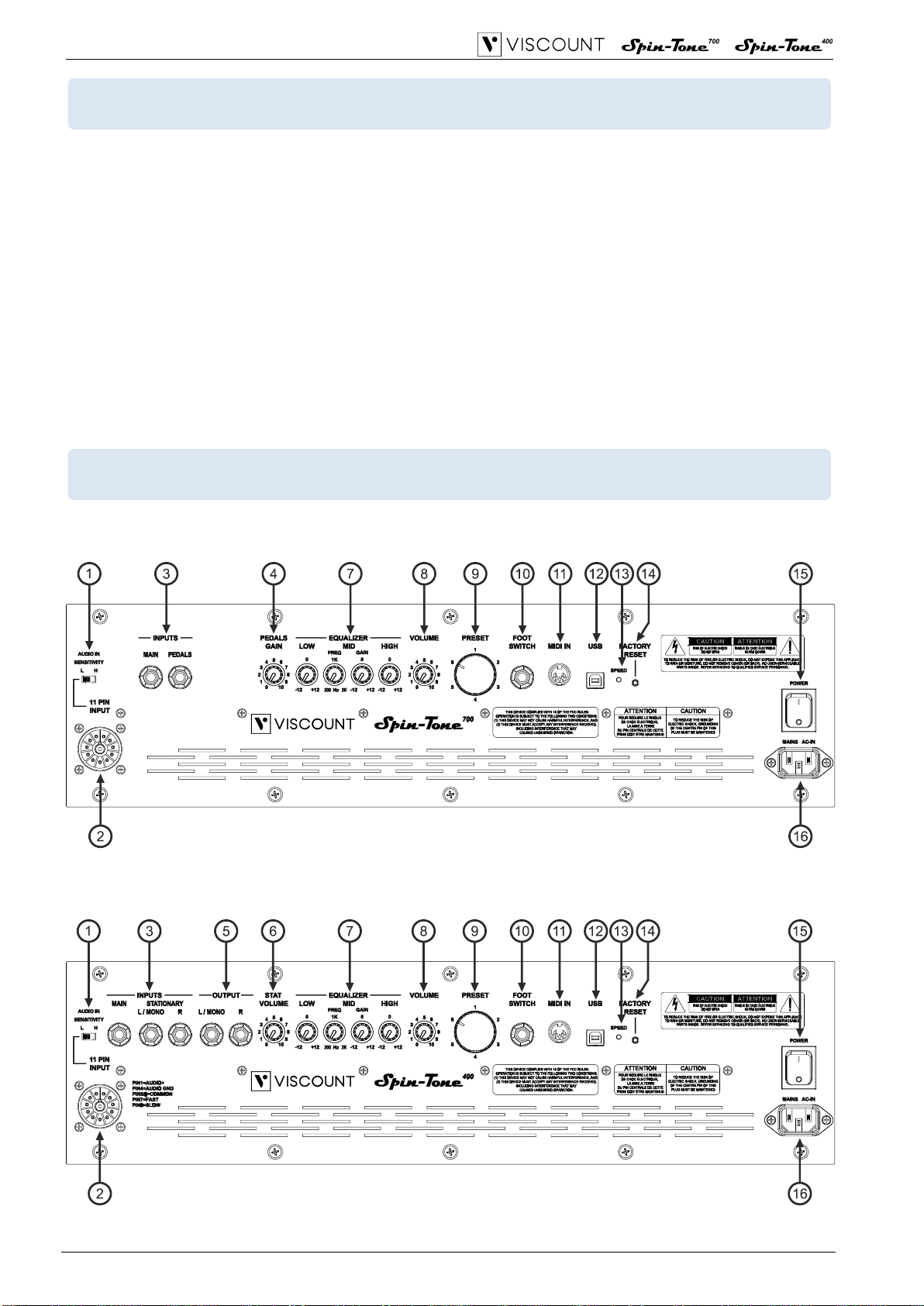
Connections .......................3 pins IEC 250 VAC, 2 unbalanced input jacks, jack foot-switch pedal, USB B
Type, MIDI IN, UNDECAL 11 pin connector
Controls ..............................11 pin input sensitivity selector, Pedal input gain, Volume, Equalizer (Bass - Mid
Gain - Mid Frequency - Treble), rotative presets selector, Rotary speed Led,
Factory Reset
Speakers.............................2x10" woofer, 1x driver PA with rotating horn
Cabinet................................Plywood
Protections .........................Metal grids
Dimensions (W x H x D) ....cm 59 x 76 x 50 –23,2" x 30" x 19,7"
Weight.................................42,5 Kg (19,5 Kg module Upper + 23 Kg module Lower)
94 Lbs (43 Lbs module Upper + 51 Lbs module Lower)
Colors..................................Black, Red Walnut
SPIN-TONE 400
Type.....................................3 amplified channels (2 woofers and 2 tweeters with or without rotary effect + driver with
rotating horn)
Power ..................................Woofer/tweeter 150W + 150W - driver 150W
Max calculated SPL ...........114 dB
Crossover frequency.........adjustable using Rotary Editor between 800 Hz and 1,2 KHz
Subsonic filter....................Yes
Protection ...........................Compressor, short circuit, thermal
Editor Control (*)................Yes
Connections .......................3 pin IEC 250 VAC, 3 unbalanced input jacks, 2 unbalanced output jacks jack foot-
switch pedal, USB B Type, MIDI IN, UNDECAL 11 pin connector
Controls ..............................11 pin input sensitivity selector, Stationary inputs volume, Volume, Equalizer (Bass
- Mid Gain - Mid Frequency - Treble), rotative presets selector, Rotary speed Led,
Factory Reset
Speakers.............................2x5" woofer, 2x1” tweeter, 1x driver PA with rotating horn
Cabinet................................Plywood
Protections .........................Metal grids
Dimensions (W x H x D) ....cm 59 x 37 x 50 –23,2" x 14,5" x 19,7"
Weight.................................23,5 Kg –55 Lbs
Colors..................................Black, Red Walnut
(*) The Editor, available for different platforms, allows the adjustment and storage in real time of the operating and shooting
parameters for each of the available Presets. Rotation speeds, transition times, relative levels and much more can be modified
by the users to suit their needs.

Disposal of old Electrical & Electronic Equipment (Applìcable throughout the European Union
and other European countries with separate collection programs)
Dir. 2002/95/CE, 2002/96/CE e 2003/108/CE
This syrnbol, found on your product or on its packaging, indicates that this product should not be
treated as household waste when you wish to dispose of it. Instead, it should be handed overt to an
applicable collection point for the recycling of electrical and electronic equipment. By ensuring this
product is disposed of correctly, you will help prevent potential negative consequences to the
environment
and human health, which could otherwise be caused by inappropriate disposal of this product. The
recycling of materials will help to conserve natural resources. For more detailed information about the
recycling of this product, please contact your local city offi ce, waste disposal service or the retail store
where you purchased this product.
This product complies with the requirements of EMCD 2004/108/EC and LVD 2006/95/EC.
FCC RULES
NOTE: This equipment has been tested and found to comply with the limits for a Class B digital Device, persuant to Part 15 if the FCC
Rules. These limits are designed to provide reasonable protection against harmful interference in a residential installation. This
equipment generates, uses and can radiate radio frequency energy and, if not installed and used in accordance with the instruction,
may cause harmful interference to radio comunications. However, there is no guarantee that the interference will not occur in a
particular installation. If this equipment does cause harmful interference to radio or television reception, which can be determinated by
turning the equipment off and on, the user is encuraged to try to correct the interference by one or more of the following measures:
-Reorient or relocate the receiving antenna.
-Increase the separation between the equipment and receiver.
-Connect the equipment into an outlet on a circuit different from that to which the receiver is connected.
-Consult the dealer or an experienced Radio/Tv technician for help.
The user is cautioned that any changes or modification not expressly approved by the party responsable for compliance could void the
user’s authority opearate the equipment.
INFORMATIONS FCC
NOTE : Cet instrument a été controlé et il est garanti pour etre en conformité avec les spécifications techniques établies pour les
dispositifs numériques de la « Classe B » selon les normes de protection contre les interférences avec d’autres dispositifs électroniques
environnants. Cet appareil produit et utilise des fréquences radio. S’il n’est pas installé et utilisé selon les instructions contenues dans le
mode d’emploi, il peut générer des interférences. L’observation des normes FCC ne garanti pas qu’il y aura aucune interférence. Si cet
appareil est la cause d’ interférences avec une réception Radio ou TV, il est possible
de le vérifier en éteignant puis en allumant l’instrument : Vous pouvez alors résoudre le problème en suivant les procédures suivantes :
-déplacer ou orienter l’antenne de l’appareil avec lequel se manifeste l’interférence.
-déplacer cet instrument ou l’appareil avec lequel se produit l’interférence
-connecter cet instrument à une prise de courant différente afin de mettre les deux appareils sur deux circuits différents.
-consulter le revendeur ou un technicien radio/tv pour d’autres renseignements.
D’éventuelles modifications non approuvées par le constructeur peuvent annuler votre garantie de l’appareil.


IT - 1
Manuale Utente
INDICE
Note importanti......................................................................................................................................................................1
Cura del prodotto..................................................................................................................................................................1
Collegamenti.........................................................................................................................................................................1
Note riguardanti questo manuale..........................................................................................................................................1
Caratteristiche generali di Spin-Tone................................................................................................................................2
Pannello di collegamento e controllo................................................................................................................................2
Installazione di Spin-Tone 700............................................................................................................................................5
Specifiche tecniche...............................................................................................................................................................6
NOTE IMPORTANTI
CURA DEL PRODOTTO
•Non applicate eccessiva forza alle strutture ed ai comandi del prodotto (pulsanti, interruttori, ecc…).
•Non collocate, quando possibile, il prodotto in prossimità di unità che producano forti interferenze come
apparecchi radio –TV, monitor, ecc...
•Evitate di posizionare il prodotto in prossimità di fonti di calore, in luoghi umidi o polverosi o nelle vicinanze di
forti campi magnetici.
•Evitate di esporre il prodotto all’irradiazione solare diretta.
•Non introdurre per nessuna ragione oggetti estranei o liquidi di qualsiasi genere all’interno del prodotto.
•Per la pulizia usate solo un pennello morbido od aria compressa, non usate mai detergenti, solventi od alcool.
COLLEGAMENTI
•Prima di effettuare i collegamenti accertatevi che tutte le casse che state utilizzando siano spente. Eviterete
rumorosi se non pericolosi picchi di segnale. Utilizzate sempre cavi schermati di buona qualità. Quando
scollegate i cavi dalle prese abbiate cura di afferrarli per il connettore e non per il cavo stesso; avvolgendoli,
inoltre, evitate nodi e torsioni.
•In caso di lunghi periodi di inutilizzo del prodotto scollegate la spina della presa di corrente.
•Collegate il cavo di alimentazione ad una presa di corrente provvista di contatto di terra.
•Accertatevi che la tensione di rete corrisponda a quella indicata sulla targhetta matricola dell’apparato.
•Controllate periodicamente la pulizia della spina elettrica.
•Utilizzate solo il cavo di alimentazione fornito in dotazione.
•Non posizionare il cavo di alimentazione in prossimità di fonti di calore. Non piegarlo eccessivamente, né
danneggiarlo.
•Non posizionare oggetti pesanti sul cavo, né collocarlo in luoghi dove potrebbe essere calpestato.
NOTE RIGUARDANTI QUESTO MANUALE
•Conservate con cura questo manuale.
•Il presente manuale costituisce parte integrante del prodotto. Le descrizioni e le illustrazioni contenute nella
presente pubblicazione si intendono non impegnative.
•Ferme restando le caratteristiche essenziali del prodotto, il costruttore si riserva il diritto di apportare eventuali
modifiche di parti, dettagli ed accessori che riterrà opportune per il miglioramento del prodotto o per esigenze
di carattere costruttivo o commerciale, in qualunque momento e senza impegnarsi ad aggiornare
tempestivamente questa pubblicazione.
•Tutti i diritti sono riservati, è vietata la riproduzione di qualsiasi parte di questo manuale, in qualsiasi forma,
senza l’esplicito permesso scritto del costruttore.
•Tutti i marchi citati all’interno del manuale sono di proprietà delle rispettive case produttrici.
•Leggete attentamente tutte le informazioni descritte. Eviterete inutili perdite di tempo ed otterrete le migliori
prestazioni dal prodotto.
•Le sigle od i numeri riportati tra parentesi quadre [ ] stanno ad indicare i nomi dei comandi e connettori dello
strumento. Per esempio la scritta [VOLUME] indica il potenziometro VOLUME.

IT - 2
Manuale Utente
CARATTERISTICHE GENERALI DI SPIN-TONE
Gli amplificatori della serie Spin-Tone incorporano un sistema ibrido con una tromba rotante nella parte superiore
e potenti woofer nella parte inferiore appositamente progettati per ricreare gli altoparlanti rotanti originali.
Spin-Tone 700 (750W) rappresenta il modello più potente della linea, è dotato di 3 canali amplificati per un driver
con tromba e 2 woofer che garantiscono l’effetto rotante.
Spin-Tone 400 (400W) è anch’esso dotato di 3 canali amplificati con un driver con tromba e 2 woofer accoppiati
però a 2 tweeter, in quanto è possibile utilizzare il dispositivo anche come un normale amplificatore statico da
collegare a qualsiasi tipo di strumento.
Entrambi i modelli dispongono di un pannello posteriore che raccoglie i principali controlli per una veloce
configurazione del diffusore, come la regolazione dell’equalizzatore, dei volumi, la selezione di uno dei 6 preset
di funzionamento e risposta timbrica, ed i connettori di collegamento.
Le velocità di rotazione Slow / Fast o l’arresto sono selezionabili tramite il controllo a leva del vostro Legend o
Legend Soul collegato al connettore a 11-pin, oppure tramite un pedale foot-switch o via MIDI.
E’ inoltre disponibile nel sito www.viscountinstruments.com l’applicazione Rotary Editor, compatibile con
Windows, MacOs, iOs, che permette la regolazione fine dei più importanti parametri di configurazione e
l’aggiornamento software di Spin-Tone.
PANNELLO DI COLLEGAMENTO E CONTROLLO
Spin-Tone 700
Spin-Tone 400

IT - 3
Manuale Utente
1. Selettore [SENSITIVITY]: selettore della sensibilità di ingresso dell’amplificatore al connettore [11 PIN
INPUT]. La posizione L, sensibilità bassa, è consigliata per gli organi della serie Legend Soul; la posizione
H, sensibilità alta, è consigliata per gli organi della serie Legend.
2. Connettore [11 PIN INPUT]: connettore a 11 pin per il collegamento dello strumento che si desidera
amplificare. Tramite questo connettore inoltre, utilizzando il comando per la gestione del diffusore rotante
presente sullo strumento collegato, è possibile selezionare le velocità alta (Fast) o bassa (Slow) di rotazione
degli altoparlanti o di fermare il motore (Brake).
3. Connettori [INPUTS]:
- [MAIN]: connettore jack sbilanciato per il collegamento del solo segnale audio dello strumento che si
desidera amplificare con effetto rotante. Con l’applicazione Rotary Editor è inoltre possibile scegliere se
avere o meno l’effetto rotante nei woofer. Con gli organi della serie Legend Soul e Legend l’utilizzo di
questo connettore è consigliato per amplificare le sezioni Upper e Lower, collegando l’uscita [MAIN
L/MONO] del Legend Soul o [MAIN LEFT] o [MAIN RIGHT] del Legend.
- [PEDALS] (presente solo su Spin-Tone 700):connettore jack sbilanciato per il collegamento del segnale
audio dello strumento che si desidera amplificare senza effetto rotante e diffondere con i soli woofer. Con
gli organi della serie Legend Soul e Legend l’utilizzo di questo connettore è consigliato per amplificare la
sezione Pedals,collegando l’uscita [PEDALS] dell’organo.
- [STATIONARY] (presente solo su Spin-Tone 400):connettori jack sbilanciati per il collegamento del
segnale audio dello strumento che si desidera amplificare senza effetto rotante. In caso di sorgente
monofonica utilizzare il solo connettore [L/MONO]. Con gli organi della serie Legend Soul e Legend
l’utilizzo di questo connettore è consigliato per amplificare la sezione Pedals, collegando l’uscita
[PEDALS] dell’organo.
4. Potenziometro [PEDALS GAIN] (presente solo su Spin-Tone 700): potenziometro di regolazione del
guadagno del segnale in ingresso al connettore [PEDALS]. Posizionando la manopola su “0“ il segnale risulta
completamente chiuso.
5. Connettori [OUTPUTS] (presenti solo su Spin-Tone 400): da questi connettori è possibile prelevare il
segnale in ingresso ai connettori [MAIN] (con o senza effetto rotante) e/o [STATIONARY], in base alla
selezione effettuata nell’applicazione Rotary Editor, per il collegamento in cascata di più amplificatori.
6. Potenziometro [STAT VOLUME] (presente solo su Spin-Tone 400): potenziometro di regolazione del
volume del segnale in ingresso ai connettori [STATIONARY]. Posizionando la manopola su “0“ il segnale
risulta completamente chiuso.
7. Sezione EQUALIZER:
Questa sezione comprende i controlli dell’equalizzatore interno semi-parametrico per il segnale in ingresso
ai connettori [MAIN] e [PEDALS]:
- Potenziometro [LOW]: permette di regolare l’attenuazione (da 0 a -12 dB) o l’esaltazione (da 0 a +12
dB) delle basse frequenze (inferiori ai 200 Hz).
- Potenziometro [MID FREQ]: permette di selezionare la frequenza che viene poi attenuata o esaltata dal
potenziometro [MID GAIN]. Il range di frequenze selezionabili è di 200 Hz –2 KHz.
- Potenziometro [MID GAIN]: permette di regolare l’attenuazione (da 0 a -12 dB) o l’esaltazione (da 0 a
+12 dB) dei segnali attorno alla frequenza regolata con il potenziometro [MID FREQ].
- Potenziometro [HIGH]: permette di regolare l’attenuazione (da 0 a -12) o l’esaltazione (da 0 a +12) delle
alte frequenze (superiori ai 2 KHz).
N.B.
E’ possibile collegare uno strumento al connettore [11 PIN INPUT] utilizzando
esclusivamente un cavo con connettore ad 11 pin (non fornito con l’amplificatore).
Il connettore [11 PIN INPUT] ha la seguente pinout:
1: Audio +
4: Audio GND
5 - 6: comune della commutazione di velocità
7: Fast
8: Slow
2 - 3 - 9 - 10 - 11: N.C.
In caso di connettore di collegamento differente è comunque possibile utilizzare appositi adattatori.
Pin 1
Pin 2 Pin 3 Pin 4
Pin 5
Pin 6
Pin 7
Pin 8
Pin 9
Pin 10
Pin 11

IT - 4
Manuale Utente
8. Potenziometro [VOLUME]: potenziometro di regolazione del volume di uscita all’amplificatore. Posizionando
la manopola su “0“ il segnale risulta completamente chiuso.
9. Selettore [PRESET]: manopola di selezione di uno dei 6 Preset. L’applicazione Rotary Editor permette la
regolazione e la memorizzazione in tempo reale dei parametri operativi dei Preset. Velocità di rotazione, tempi
di transizione, livelli relativi e molto altro possono essere modificati dall’utente in base alle proprie esigenze e
gusti e memorizzati nei Preset del Spin-Tone 700 e Spin-Tone 400.
10. Connettore [FOOT SWITCH]: connettore jack per collegare un foot switch con cui si desidera selezionare le
velocità di rotazione dei diffusori. E’ possibile utilizzare pedali:
- a singolo switch: le velocità Slow / Fast vengono selezionate con la pressione corta del pedale, mentre
tenendolo premuto per alcuni istanti viene fermata la rotazione (Brake).
- a doppio switch: uno switch assume la funzione Brake / Go, l’altro la selezione delle velocità Slow / Fast.
11. Connettore [MIDI IN]: connettore MIDI a cui collegare lo strumento per la selezione delle velocità ed arresto
tramite messaggi MIDI. In condizioni di default vengono ricevuti i seguenti Control Change (su qualsiasi
canale):
- CC66=0: velocità Slow
- CC66=127: velocità Fast
- CC67=0: Brake off
- CC67=127: Brake on
- CC68=0: Brake on
- CC68=64: velocità Slow
- CC68=127: velocità Fast
12. Connettore [USB]: connettore USB a cui collegare il computer o tablet con cui utilizzare l’applicazione Rotary
Editor.
13. Led [SPEED]: Led che visualizza la velocità attualmente selezionata, secondo la regola:
- verde: Brake
- rosso: Fast
- arancio: Slow
14. Pulsante [FACTORY RESET]: pulsante per il ripristino delle impostazioni di fabbrica. Per effettuare un
Factory Reset tenere premuto, utilizzando un utensile appuntito come una penna o un piccolo cacciavite, il
pulsante all’accensione di Spin-Tone 700 e Spin-Tone 400. Al termine della procedura il Led [SPEED]
lampeggerà tre volte.
15. Interruttore [POWER]: interruttore di accensione e spegnimento di Spin-Tone 700 e Spin-Tone 400.
16. Presa [MAINS AC-IN]: presa di alimentazione alla corrente di rete.
N.B.
E’ necessario selezionare il tipo di pedale utilizzato nell’applicazione Rotary Editor. In condizioni di default viene assunto
l’utilizzo di un pedale a singolo switch.
N.B.
- Tramite l’applicazione Rotary Editor è possibile scegliere quali Control Change utilizzare per la gestione delle
velocità e arresto.
- E’ altresì possibile utilizzare il seguente codice di Sistema Esclusivo per la selezione delle velocità:
F0 41 10 00 08 12 02 00 10 3D 0x 00 F7, dove
X=0: velocità Slow
X=1: velocità Fast
N.B.
Una volta effettuato il Factory Reset tutte le modifiche ai parametri e impostazioni apportate e memorizzate in
precedenza verranno irrimediabilmente perse.

IT - 5
Manuale Utente
INSTALLAZIONE DI SPIN-TONE 700
Spin-Tone 700 è composto di due moduli, uno (Upper) comprendente il pannello di controllo e la tromba rotante,
l’altro (Lower) contenente i woofer. Per procedere con il montaggio del sistema, seguire le istruzioni di seguito
riportate.
1. Posizionare il modulo Upper 1sopra al modulo
Lower 2, avendo cura di orientare i moduli in modo
che i connettori 1A e 2A siano sullo stesso lato e di
alloggiare i piedi 1B del modulo Upper 1negli
alloggiamenti 2B presenti sul lato superiore del
modulo Lower 2.
2. Collegare il cavo 3fornito in dotazione con
l’amplificatore nei connettori 1A e 2A.

IT - 6
Manuale Utente
SPECIFICHE TECNICHE
SPIN-TONE 700
Caratteristiche....................3 vie amplificato (2 woofer con o senza effetto rotante + driver con tromba rotante)
Potenza ...............................Woofer 300W + 300W - driver 150W
SPL massimo calcolato.....127 dB
Frequenza del filtro
di crossover........................regolabile con Rotary Editor da 800 Hz a 1,2 KHz
Filtro subsonico.................Si
Protezione...........................Compressione, corto circuito, termico
Controllo con editor (*)......Si
Connessioni .......................3 pin IEC 250 VAC, 2 jack sbilanciati del segnale di ingresso, jack per
collegamento pedale switch, USB B Type, MIDI IN, connettore UNDECAL 11 pin
Controlli ..............................Selettore sensibilità di ingresso connettore 11 pin, guadagno ingresso Pedal,
Volume, Equalizer (Bass - Mid Gain - Mid Frequency - Treble), selettore Preset,
Led velocità di rotazione, Factory Reset
Altoparlanti.........................2x10" woofer, 1x driver PA con tromba rotante
Cabinet................................Pioppo
Protezione...........................Griglie in metallo
Dimensioni (L x A x P).......cm 59 x 76 x 50 –23,2" x 30" x 19,7"
Peso ....................................42,5 Kg (19,5 Kg modulo Upper + 23 Kg modulo Lower)
94 Lbs (43 Lbs modulo Upper + 51 Lbs modulo Lower)
Colori...................................Nero, Noce Rosso
SPIN-TONE 400
Caratteristiche....................3 vie amplificato (2 woofer e 2 tweeter con o senza effetto rotante + driver con tromba
rotante)
Potenza ...............................Woofer/tweeter 150W + 150W - driver 150W
SPL massimo calcolato.....114 dB
Frequenza del filtro
di crossover........................regolabile con Rotary Editor da 800 Hz a 1,2 KHz
Filtro subsonico.................Si
Protezione...........................Compressione, corto circuito, termico
Controllo con editor (*)......Si
Connessioni .......................3 pin IEC 250 VAC, 3 jack sbilanciati del segnale di ingresso, 2 jack sbilanciati del
segnale di uscita, jack per collegamento pedale switch, USB B Type, MIDI IN,
connettore UNDECAL 11 pin
Controlli ..............................Selettore sensibilità di ingresso connettore 11 pin, volume ingressi Stationary,
Volume, Equalizer (Bass - Mid Gain - Mid Frequency - Treble), selettore Preset,
Led velocità di rotazione, Factory Reset
Altoparlanti.........................2x5" woofer, 2x1” tweeter, 1x driver PA con tromba rotante
Cabinet................................Pioppo
Protezione...........................Griglie in metallo
Dimensioni (L x A x P).......cm 59 x 37 x 50 –23,2" x 14,5" x 19,7"
Peso ....................................23,5 Kg –55 Lbs
Colori...................................Nero, Noce Rosso
(*) L'Editor, disponibile per diverse piattaforme, permette la regolazione e la memorizzazione in tempo reale dei parametri di
funzionamento e di ripresa per ciascuno dei Preset disponibili. Velocità di rotazione, tempi di transizione, livelli e molto altro
possono essere modificati dall’utente in base alle proprie esigenze.

Smaltimento dei rifiuti elettrici ed elettronici (applicabile nell’Unione Europea e negli altri paesi
europei con servizio di raccolta differenziata)
Ai sensi dell’art. 13 del Decreto legislativo 25 luglio 2005, n. 151 “Attuazione delle Direttive
2002/95/CE, 2002/96/CE e 2003/108/CE”
II simbolo presente sul prodotto o sulla sua confezione indica che il prodotto non verrà trattato come
rifiuto domestico. Sarà invece consegnato al centro di raccolta autorizzato per il riciclo dei rifi uti
elettrici ed elettronici. Assicurandovi che il prodotto venga smaltito in modo adeguato, eviterete un
potenziale impatto negativo sull’ambiente e la salute umana, che potrebbe essere causato da una
gestione non conforme dello smaltimento del prodotto. Il riciclaggio dei materiali contribuirà alla
conservazione delle risorse naturali. Per ricevere ulteriori informazioni più dettagliate Vi invitiamo a
contattare l’uffi cio preposto nella Vostra città, il servizio per lo smaltimento dei rifi uti o il negozio in
cui avete acquistato il prodotto.
Lo smaltimento del prodotto da parte dell’utente comporta l’applicazione delle sanzioni amministrative
previste dalla normativa di legge.
Questo prodotto è conforme ai requisiti delle direttive EMCD 2004/108/EC e LVD 2006/95/EC.

User Manual –Manuale Utente
BLOCK DIAGRAM – SCHEMA A BLOCCHI
Spin-Tone 400 Spin-Tone 700


Viscount International S.p.A.
Via Borgo, 68 / 70 – 47836 Mondaino (RN), ITALY
Tel: +39-0541-981700 Fax: +39-0541-981052
Website: www.viscountinstruments.com
This manual suits for next models
1
Table of contents
Languages:
Other Viscount Amplifier manuals
Popular Amplifier manuals by other brands

Scientific Atlanta
Scientific Atlanta System Amplifier III Installation and operation guide

Texas Instruments
Texas Instruments TPA3120D2 user manual

Kenwood
Kenwood W-38 Installation and operating manual

dbx
dbx 286A Specification sheet

Toa
Toa A-9120S Specifications

Texas Instruments
Texas Instruments TPA0252 user guide