Toa A-503A User manual

TOA Electronics Amplifier Guide
4õ 8
8
õ
VOL
VOL
REMT
REMT
OUT
OUT
IN/
IN/
BRG
BRG
OUT
OUT
AMP
AMP
PRE
PRE
IN
IN
AMP
AMP
PWR
PWR
OUT
OUT
AUX
AUX
MUTE
MUTE
1
MUTE
MUTE
2
GND
GND
60W
60W
60Hz
60Hz
120V
120V
COM
COM
DIRECT
DIRECT
25V
25V
70V
70V
UNSWITCHED AC 120V 60Hz
MAX 500W 4A
MAX 500W 4A
AC
AC
PROTECT
PROTECT
POWER
POWER
PEAK
PEAK
NORMAL
NORMAL
SIGNAL
SIGNAL
MASTER
MASTER
ON
ON
OFF
OFF
TONE DEFEAT
TONE DEFEAT
TREBLE
TREBLE
BASS
BASS
INPUT 8
INPUT 8
INPUT 7
INPUT 7
INPUT 6
INPUT 6
INPUT 5
INPUT 5
INPUT 4
INPUT 4
INPUT 3
INPUT 3
INPUT 2
INPUT 2
INPUT 1
INPUT 1
ON
ON
OFF
OFF
LOW CUT
LOW CUT
OFF
OFF
ON
ON
PROGRAM
PROGRAM
10
0
MIC
MIC
0
TEL
TEL
10
010
10
10
10
0
AUX
AUX
010
10
MODULE
MODULE
SIGNAL
SIGNAL
POWER
POWER
ON
ON
OFF
OFF
PEAK
PEAK
HOT
HOT
COM
COM
120V 60Hz
120V 60Hz
120V 50Hz
120V 50Hz
UNSWITCHED
UNSWITCHED
150W
150W
MAX 500W
MAX 500W
CLASS 2 WIRING
CLASS 2 WIRING
PROGRAM
PROGRAM
OUTPUT 120W
OUTPUT 120W
COM
COM
4õ
OUTLET
OUTLET
4A
4A
BREAKER
BREAKER
GCOM
COM
70V
70V
25V
25V
8õ
OUTPUT 1W
OUTPUT 1W
RESET
RESET
PUSH
PUSH
HOT
HOT
G
TEL
TEL
COM
COM
10
10
NC
NC
RESET
RESET
MUTE
MUTE
COM
COM
MOH
MOH
600
600
õG
MIC
MIC
COM
COM
UNIT
UNIT
G
4A
4A
BREAKER
BREAKER
HOT
HOT
PUSH
PUSH
OUTPUT 1W
OUTPUT 1W
0
- +
0
SENSE
SENSE
BASS
BASS
0
10
10
AUX
AUX
PREAMP
PREAMP
10
10
MOH
MOH
0
- +
OUT
OUT
MUTE
MUTE
TREBLE
TREBLE
A
0
B
POWER
POWER
IN
IN
MODULE
MODULE
PAGE
PAGE
BGM
BGM
COM
COM
HOT
HOT
INPUT LEVEL
INPUT LEVEL
LOW CUT
LOW CUT
-20dBV
-20dBV
OFF
OFF
ON
ON
INPUT
INPUT
DC FUSE
DC FUSE
DC FUSE
DC FUSE
250V 8A
250V 8A
250V 8A
250V 8A
250V 7A
250V 7A
AC FUSE
AC FUSE
S.
R
LISTED
LISTED
COMMERCIAL
COMMERCIAL
AUDIO EQUIP.
AUDIO EQUIP.
111J
111J
OU
0dBV
0dBV
NOR
PO
OFF
ON
OUT
OUT
IN/
IN/
BRG
BRG
OUT
OUT
AMP
AMP
PRE
PRE
IN
IN
AMP
AMP
PWR
PWR
OUTPUT 1W
OUTPUT 1W
- +
0
BASS
BASS
0
10
10
AUX
AUX
PREAMP
PREAMP
MOH
MOH
- +
OUT
OUT
MUTE
MUTE
TREBLE
TREBLE
A
0
B
POWER
POWER
IN
IN
MODULE
MODULE
PAGE
PAGE
BGM
BGM
4õ8
8
õ
VOL
VOL
REMT
REMT
MUTE
MUTE
1
MUTE
MUTE
2
GND
GND
60W
60W
60Hz
60Hz
120V
120V
COM
COM
DIRECT
DIRECT
25V
25V
70V
70V
UNSWITCHED AC 120V 60Hz
MAX 500W 4A
MAX 500W 4A
AC
AC
Guide

TOA Electronics Amplifier Guide

Table of Contents
Introduction............................................................................................................................................................................1
Chapter 1: Selecting An Amplifier......................................................................................................................2
Sound Sources..........................................................................................................................................2
Speaker Requirements........................................................................................................................2
System Function......................................................................................................................................2
Chapter 2: Amplifier Basics......................................................................................................................................4
Signal Flow..................................................................................................................................................4
Audio Levels...............................................................................................................................................8
Impedance................................................................................................................................................10
Chapter 3: Amplifier/Speaker Matching.....................................................................................................11
Low Impedance Systems................................................................................................................11
High Impedance (70.7/25Volt) Distributed Line Systems.....................................12
How to Design a High Impedance Distributed System...........................................13
Chapter 4: Wiring..........................................................................................................................................................14
Low Level and Line LevelWiring..............................................................................................14
Twisted PairWiring..............................................................................................................15
Shielded and Unshielded Cable.................................................................................15
Balanced and Unbalanced Lines...............................................................................15
Transformer Isolation.........................................................................................................16
Speaker LevelWiring.........................................................................................................................16
Minimizing Line Loss..........................................................................................................16
Troubleshooting Guide...............................................................................................................................................17
LoadTroubleshooting......................................................................................................................17
PowerTap to Impedance Conversion Chart....................................................................17
TOA Amplifier Overview............................................................................................................................................18
TOA Amplifier Comparison Chart...............................................................................................................21-22
Appendix A: Wire Size Charts.............................................................................................................................A-1
Appendix B: Power Consumption & Thermal Dissipation...........................................................A-2
TOA Electronics Amplifier Guide

TOA Electronics Amplifier Guide
Welcome to the TOA Amplifier Guide!
TOAhasbeenprovidingcompletesoundsystemssince1934. AfterourfirstU.S.salesofficewasestab-
lished in 1974, our TA-900 Series mixer/amplifiers quickly gained recognition for their unmatched
combinationofflexibility,reliability,andperformance. Sincethattime,TOAhassteadilyexpandedand
improved our line of amplifiers,mixer/amplifiers,and associated electronics. TheTOA 900 Series,now
inits3rdgenerationofproductdesign,isrenownedforitsflexiblemodulararchitechture,elegantsim-
plicity of operation,and bulletproof reliability. Thenew BG-M Seriesbuilds furtheron our traditionby
offering the flexibility of a module port in a package that is remarkably affordable without sacrificing
either performance or reliability. With six distinct series of amplifiers and mixer/amplifiers to choose
from,plus a range of mixers,signal processors,and now network audio,TOA offers the most compre-
hensive line of audio electronics for systems contractors.
TheTOA Amplifier Guide is a sound system design tool aimed at helping system designers,sales staff,
installers and end users select the right amplifiers and accessories for their applications. It includes a
review of the basic concepts of audio amplification,such as signal flow, levels, and impedance,plus
useful references such as thermal dissipation,power consumption and line loss charts,as well as tips
for troubleshooting (including impedance measurement). Further information on speaker system
design and speaker selection and placement may be found in the TOA Speaker Guide, available for
download at www.toaelectronics.com.
Disclaimer: This design guide does not cover all of the general concepts underlying sound system design
and installation, which would require several hundred pages. This guide is not meant to replace the par-
ticipation of an experienced consultant or engineer.
References: For more in-depth coverage of sound system design principles,we recommend the fol-
lowing two excellent books:
Sound System Engineering, Second Edition, Don & Carolyn Davis, 1975, 1987 by Howard Sams & Co.
ISBN:0-672-21857-7
Handbook for Sound Engineers:Third Edition,GlenBallou,Editor,2001,Butterworth &Heinemann. ISBN:
0-240-80454-6
Acknowledgements
Thanks to Steve Mate, Lucas Marciniak, and Martin Gonzalez in the TOA Product Support Group for
their invaluable support and contributions to this project,and to Geraldine Vargas for designing the
layout. This guide is dedicated to the memory of my late father,whose amp-building projects on the
kitchen table gave me a love for the smell of solder,and whose demonstrations of loudspeaker sensi-
tivity gave me a love for the art of sound system design.
David Menasco
Product Application Specialist
TOA Electronics,Inc.
1

2
TOA Electronics Amplifier Guide
Chapter 1: Selecting An Amplifier
Amplifiers are the heart of any sound system. In addition to providing the audio power for a system,
amplifiers may also incorporate the input mixing and control functions vital to a system’s operation
(such an amp is called a mixer/amplifier). Selecting the right amplifier or mixer/amplifier for a job
means choosing a set of features and characteristics suited to meet the customer’s needs. The main
characteristics of an amplifier or mixer/amplifier include:The number and type of input channels,the
number of busses (signal paths) and output channels,and the amount of output power per channel.
Dimensions,weightandotherbasicparametersmayalsobeimportant,dependingontheinstallation.
Features needed for a job may include:Auto-muting (e.g.voice-over-music),remote volume control,
transformer-isolated inputs/outputs, phantom power, bass/treble controls, multi-level muting, rack
mounting,equalization,or any of a number of other special purpose features.
When selecting an amplifier,there are three key questions to consider:
1. What sound sources will be used?
2. What speakers will it be driving?
3. How does the client or end user need the system to operate?
Answerstothesequestionswilldictatewhatcharacteristics and featuresare needed. Belowisamore
detailed look at each question.
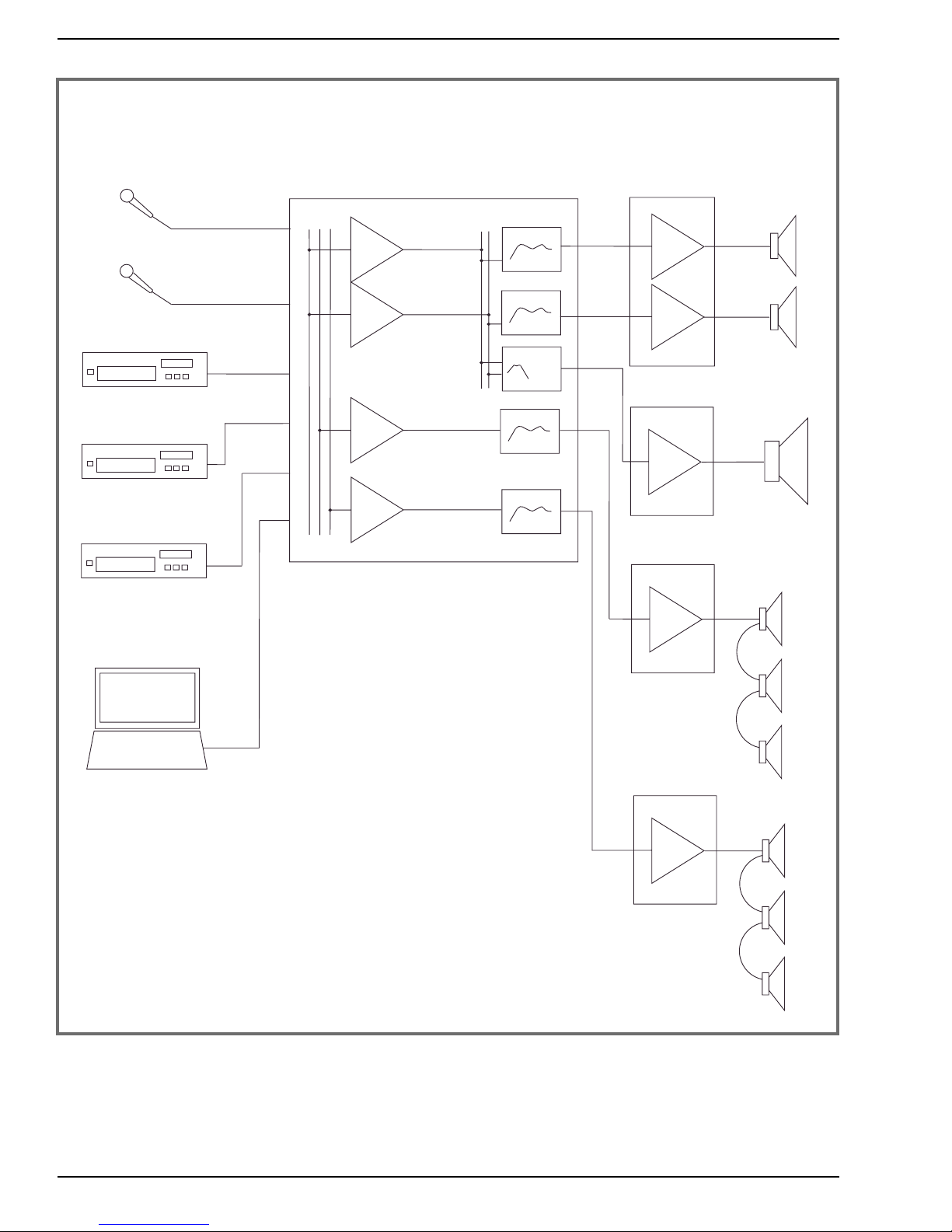
Sound Sources
One of the first questions you will need to answer,at least in general,is what sound sources will be
usedinthesystem. Willthesystembeusedwithmicrophones? ACDplayer? Atelephoneexchange?
Due to standardization,many sources can be treated similarly — for example, CD and DVD players,
VCRs and computer sound cards all provide unbalanced line level outputs,usually with a similar out-
put level,and thus may be treated the same in the design phase. But it is still important to know how
many such sources you will have,and what other sources may also be used.
Speaker Requirements
Two more key questions when selecting an amplifier is how much power is needed,and what kind of
load(impedance)thespeakerswillpresent—andhere,theanswerswilldependonthetypeofspeak-
ers used. It is usually preferable to select the speakers,or at least the general type of speakers,before
selecting the amplifier. Please refer to the TOA Speaker Guide for information on selection and place-
ment of speakers. Once the type of speakers has been determined, it will be possible to choose an
amplifier with adequate power and an appropriate output impedance. See Chapter 3
“Amplifier/Speaker Matching”for discussions of impedance,power levels,and 70.7V/25V line operation.
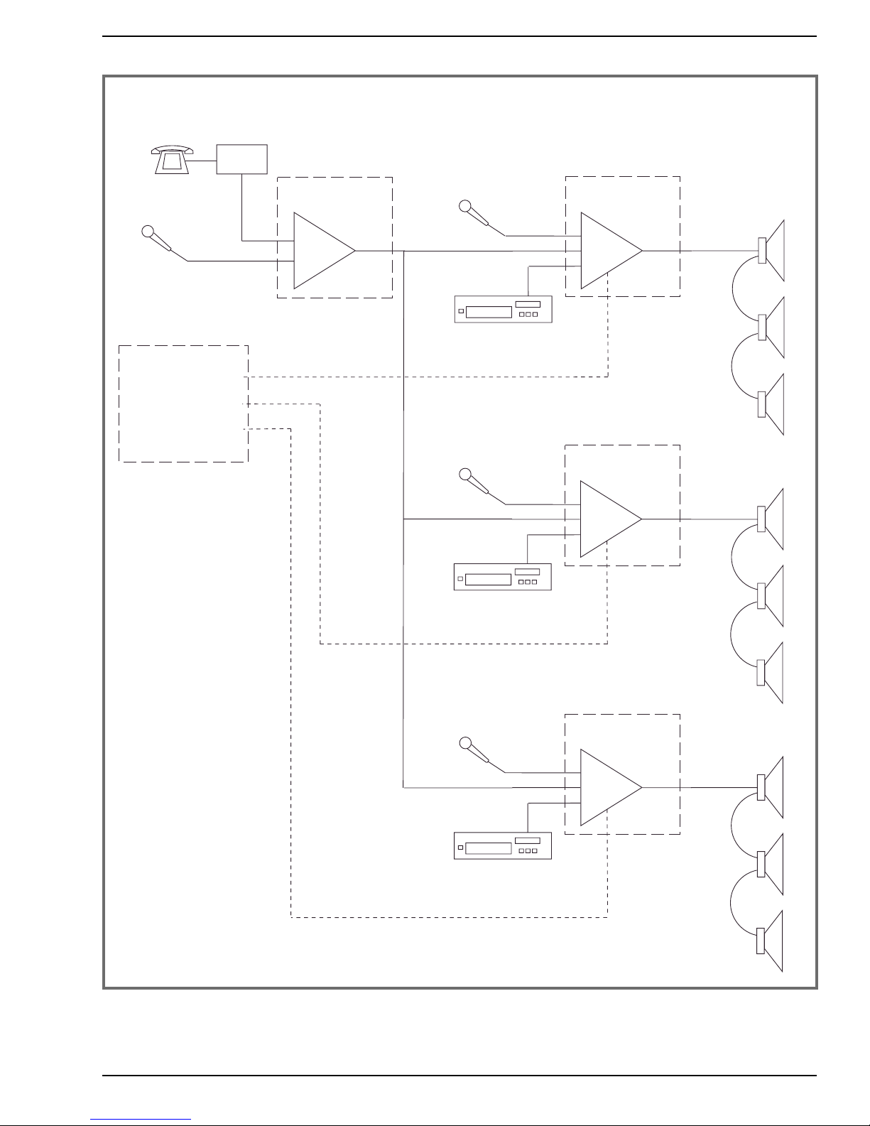
System Function
The paramount rule of sound system design is almost too obvious, and yet it is all too often over-
looked: it is important to let the system design be guided by the needs of the client or end user,and
the function they need the system to fill. For example,if they need the mic to automatically mute the
music,you will need a mixer/amplifier that includes this feature. Often,the user won’t be very

TOA Electronics Amplifier Guide
3
specificuntilafterthesystemisinstalledandtheytrytomakeitwork. Thedesigner’sjobincludesask-
ing enough questions in the beginning to make sure the design will meet the client’s needs. As a
start, imagine yourself in the place of your client, using the system, and asking questions such as
“wherewillthisgo?”and“how will this work?” Experiencehelpsalotinthisprocess,butinstallersand
designers of all levels of experience can save time and headaches by asking some basic questions at
the outset.
Visit us at
www.toaelectronics.com
to download the
TOA Speaker Design Guide!

4
TOA Electronics Amplifier Guide
Chapter 2: Amplifier Basics
Important Concepts: Signal Flow, Level and Impedance
When designing and installing sound systems,mastery of some key concepts helps a great deal. A
basic understanding of signal flow,levels,and impedance can increase your efficiency on the job,and
dramatically reduce the number of costly call-backs.
Signal Flow: The Audio Chain
Signal Flow refers to the path of the sound from the source (page announcement,CD player,satellite
receiver,etc.) to the listener. This path can be very simple,using just a single source,a power amplifi-
er,and one or more speakers,or it can be complex,having multiple sources,multiple paths,and mul-
tiple destinations,with extra processing stages. A typical paging system signal path will begin with
two or three sources — for example,background music,paging audio from the phone system,and a
microphone(seefig.1). Thesewillbefedintoamixer,whichcombinesthesourcesintoonesingleline.
Themixeroutputmaybe fed into anequalizer,compressoror other processor,ordirectly toan ampli-
fier. The amplifier increases the power of the signal and feeds it to the speakers. In most smaller sys-
tems, the mixer and amplifier sections are integrated in one unit, which may include a built-in or
optional processing stage,such as an equalizing module for premium speakers.
Σ
Mixer Amplifier
PBX
Phone System
Microphone
Music Source
Processor
(optional)
Sources Mixer/Amplifier Speakers
Figure 1: Basic System for Paging and Background Music

5
TOA Electronics Amplifier Guide
Σ
Mixer Amplifier
PBX
Phone System
Microphone
Music Source
Processor
(optional)
Sources Mixer/Amplifier Speakers
to Phone System
Music on Hold input
Figure 2: Basic System Plus Music-On-Hold Output
Morecomplexsystemsincludeallthesesamestages—sources,mixing,processing,amplification,and
speakers — but may add additional signal paths (called busses) so that some sources or listening
areas can be treated differently. A common addition to the typical paging system is the Music On
Hold (MOH) output bus. This bus is fed from the music input,and not affected by speaker processing
modulesor by mute functions used fortheoverheadpaging (see fig.2).TOA900 Seriesamplifiers can
provide an MOH output using the T-12S module, which provides for both the music input and the
MOH output. This module also works with the 900 Series mute bus to allow for muting of the music
duringpaging announcements tothemain output,whilethe separate MOH outputis not mutedand
receives no page announcement. TOA BG and BG-M Series amplifiers include MOH outputs as stan-
dard features.
Zone paging and multimedia systems can use additional signal paths to route sounds to different
areas (see figs.3 and 4). Figure 3 shows a typical 3-zone paging system for central mic and/or tele-
phone paging with background music. Simple contact closures, provided by the phone system or
contractor, are used to activate the zones in any desired combination, simultaneously muting the
background music in each activated zone. TOA BG-M Series amplifiers offer an especially economical
solution for this type of zone paging system. The background music may be from sources local to
each zone or distributed from the head-end via the MOH output.
In multimedia applications, multiple signal paths can be used to route speech and music or movie
sound to different speakers,allowing precise matching of speaker type for the intended application.
Figure 4 shows a multimedia system for a lecture hall, training room, or multi-media-ready meeting
room. This system provides for stereo playback of music sources and stereo sound for video,using a
pair of speakers which may be located flanking a fixed or retractable screen, alongside distributed
mono speech. The resulting system can provide powerful and moving reproduction of music and
movie soundtracks and clear, intelligible speech. An optional subwoofer for the music feed further
enhances the impact.

Figure 3: Three-Zone Paging System
6
TOA Electronics Amplifier Guide
Σ
Microphone
BG-M Series
Mixer/Amplifier
PBX
Phone System
Σ
Music Source
BG-M Series
Mixer/Amplifier
Local
Microphone
Sources Speakers
Music Source
Σ
BG-M Series
Mixer/Amplifier
Local
Microphone
Σ
Music Source
BG-M Series
Mixer/Amplifier
Local
Microphone
Dry Contact
Closures
(one pair
per zone)
Mute
Zone 1
Mute
Zone 2
Mute
Zone 3
To 'Tel' Input
To 'Tel' Input
To 'Tel' Input

7
TOA Electronics Amplifier Guide
Σ
Σ
Σ
Σ
D-901 Mixer/Processor
IP-300D
Amplifier
P-912MK2
Amplifier
Podium
Microphone
CD/DVD Player
Sources Mixer/Amplifier Speakers
P-924MK2
Amplifier
VHS Player
Audio Cassette
Wireless
Microphone
Computer Audio
P-906MK2
Amplifier
Figure 4: Multimedia System

8
TOA Electronics Amplifier Guide
Audio Levels: Voltage, Gain and the Decibel
A basic characteristic of any audio signal is its amplitude,measured electrically in terms of voltage or
acoustically in terms of sound pressure. When assessing the loudness of a signal, the amplitude or
pressureis convertedtoadecibelvalue. Thedecibel scale givesarelativenumberreferencedtoacer-
tain voltage or pressure. For example,0 dBV is a popular standard reference for audio levels,and rep-
resents one volt. Note that amplitude is expressed as a voltage,while level (or loudness) is expressed
using a dB scale.
When working with audio electronics, levels are com-
monly divided into three ranges: mic level, line level,
and speaker level. Mic level is the smallest signal.
Microphones and other passive transducers (devices
that convert energy from one form, such as sound, to
another, such as electricity) produce signals ranging
from a few microvolts to a few millivolts. A typical nom-
inal operating level for a microphone output would be
–55 dBV. Line level is hundreds of times greater in volt-
ageterms—typically rangingfromseveralmillivoltsup
to around 1 volt,with a nominal level of 0 dBV. Speaker
level is the strongest, ranging from a fraction of a volt
(duringquiet periods) toseveraldozenvoltsdepending
on the output rating of the amplifier. Of course,sound
is very dynamic in nature, so whatever the nominal
operating level of your signal is, if you read it with a
meter during operation,you are likely to see large fluc-
tuations from moment to moment within that range.
An important function of amplifiers is providing the
“gain”neededtoraisesignalsfrommicorlinelevelupto
speaker level. Gain is another word for amplification,
and simply means an increase of the voltage or power.
The opposite of gain is attenuation. Both gain and
attenuation are commonly measured in decibels.
The dBV scale is not the only one used for audio levels.
AnotherpopularreferencescaleisthedBu,where0 dBu
represents 0.775 volts. The historical predecessor to
these two scales is the original dBm scale,where 0 dBm
represents one milliwatt, or 0.001 watts. Other scales
you might encounter include dBW (referenced to one
watt) and dBµV (referenced to one microvolt). These
scales are seen mostly in the radio broadcast industry.
Care should be taken not to confuse one scale with
another,especially the common dBV and dBu scales. To
make things especially aggravating,the term for dBu was previously dBv — with a lower-case“v”;so
if you encounter dBv on an old spec sheet,it means dBu,not dBV.
What is RMS Power?
An audio signal is defined by its amplitude
(loudness) and frequency (pitch). When the
sound is represented as a waveform,the ampli-
tude is the vertical dimension, while the fre-
quency is the number of up and down cycles of
the wave per second, with seconds running
from left to right.
Amplifier power ratings are based on the
amplitude of the waveform. Since the peak levels
of a complex waveform (one containing many
frequencies) may occur rarely or frequently, an
averaged value is used, based on the “root
mean square” or RMS method. In this method,
the amplitude is squared (so that all values are
positive), then the resulting values are aver-
aged, and the square root of this average is the
RMS value. For simple sine wave test signals,
the RMS voltage will be 0.707 times the peak
voltage. After calculating RMS voltage, the
RMS power is calculated by squaring the volt-
age and dividing by the load resistance.
Time
Amplitude
Peak
RMS Peak
to
Peak

Figure 5 shows a simplified block diagram and a level diagram,indicating gain stages inside a mixer-
amplifier,from mic and line level inputs to 70.7 volt speaker level output. The signal is amplified in
stages,withattenuators(volumecontrols)betweeneach stage toreducetheoverallgainwhenneeded.
The mic pre-amp provides 32 to 52 dB of gain,bringing the mic level signal up to a level that can be
matched with other line level sources. The summing amplifier provides additional gain,bringing all
sources up to 0 dBV. The power amplifier serves to boost the power up to a level that can drive a
speaker. Italsoprovidesalowoutputimpedanceforefficientpowertransfer. Lastly,the output trans-
formermatchestheamplifiertothe70.7voltlineandincreasesdrivevoltagetoamaximumratedout-
put of +37 dBV.
9
TOA Electronics Amplifier Guide
M-series
Input Module
Microphone
Mic
Preamp
Gain
Power
Amplifier
Link
Pre-
Amp
Out
Power
Amp
In
Trans-
former
0 dBV
+20
-20
-40
-60
+40
M-series Mic Input
-72 dBV to -52 dBV
Power Amp
70 Volt Output
+37 dBV
Mix Bus
-20 dBV
Pre-Amp
Output
0 dBV
Σ
Summing
Amplifier
Bridge
In/
Out
A-900MK2 series
Mixer/Amplifier
B-series
Input Module
Matching
Transformer
Input
Level
Master
Level
PBX
Phone System
B-series Line Input
-18 dBV
Figure 5: Block Diagram and Level Diagram of Mixer/Amplifier

Impedance
Impedance refers to the way a device reacts to the application of electric current. The device will
exhibit varying amounts of resistance and either capacitance or inductance. For our purposes, the
resistance is most important. In keeping with common practice, when we say“impedance”we will
mean resistance.
Impedance,in this sense,refers to how much resistance
the device presents to the free flow of electricity
through it. At a given drive voltage, the lower the
impedance of the receiving device, the higher will be
the current flow through it. This is important to know
when working with amplifiers, because if the load
impedance presented by the speakers is too low,it may
draw so much current that the amplifier will overwork
itself and deliver distorted sound, overheat — perhaps
even burn out.
Impedance is measured in ohms, named for Georg
Ohm, who first described the set of electrical relation-
shipsnowknownas Ohm’sLaw(see fig.6). Every device
will have both an input impedance (also called the load
impedance) and an output impedance (also called the
source impedance). Theinputimpedanceofanamplifier
could range from 600 ohms to 10,000 ohms, or even
higher (see side bar). A typical speaker impedance may range from 4 to 16 ohms.
10
TOA Electronics Amplifier Guide
Ohm's Law
W =
R =
I =V =
V2
W
V2
R
V x I
I x R
W
I
V
I
I2x R
W
I2
W x R V
R
W
V
W
R
W = Power in Watts
R = Resistance in Ohms
V = Electromotive Force in Volts
I = Current in Amperes
Figure 6
Impedance “Matching”
A common point of confusion is the concept of
“impedance matching.” Transmission line theory
states that the load impedance and source
impedance should be equal, to avoid reflec-
tions in the line. But this requirement holds
only when the line is longer than the shortest
wavelength of the signal. For audio frequen-
cies,the line would need to be over 9 miles long
for transmission line theory to apply. When
using solid-state equipment and typical cable
runs of several hundred feet or less, the best
performance is obtained when the load imped-
ance is about 5 to 20 times greater than the
source impedance. So, for example, a 10,000
ohm input is a good“match”for a 600 ohm out-
put.

11
TOA Electronics Amplifier Guide
Chapter 3: Amplifier/Speaker Matching
Interfacing between the amplifierand speakers is commonlydone in one of twoways. Smallsystems
with one or two speakers will typically use a direct connection between the speakers and the amp.
This is sometimes called low impedance operation,because the load impedance ranges from 4 to 16
ohms nominal. Systems with more than 2 speakers usually use transformers at the amp and at each
speaker to simplify impedance matching and reduce line loss. These systems are commonly called
distributed line systems,70.7 volt (or 25 volt) systems,or constant voltage systems. In both cases,speakers
should be wired in parallel (plus to plus and minus to minus).
Low Impedance Systems
Whenmatchingamplifiers with speakers,thereare a coupleof importantrules toremember. First,low
impedanceamplifieroutputsaredescribed in termsoftherecommendedloadimpedance,i.e.“4 ohm
output”or“8 ohm output”(the actual source impedance of a power amplifier output is seldom spec-
ified but is typically less than one ohm). Second: With rare exceptions, when using more than one
speaker,the speakers should be wired in parallel.
Parallelwiringalwaysresultsinalowerloadimpedancethantheindividualratingofeachspeaker. For
example, two 8 ohm speakers in parallel results in a 4 ohm load. Two 16 ohm speakers in parallel
results in an 8 ohm load. The general-purpose equation for calculating the load of multiple speakers
in parallel is shown in Figure 7. But as the above two examples illustrate,you will find that when all
the speakers have the same impedance, the total load will be equal to the rated impedance divided by
the number of speakers.
A commercial-grade speaker without any transformer may have a rated nominal impedance any-
wherefrom 4 ohms to 16ohms. Themost common ratingsare 4 ohms,8ohms or 16 ohms. Themost
common recommended load ratings for low impedance amplifier outputs are 4 ohms and 8 ohms.
Thismeans that in most cases,youwill belimited to oneor twospeakers peramp channelwhen con-
necting low impedance speakers in parallel.
Calculating Speaker Impedance
Total Impedance = 1
1
R1
+1
R2
+1
R3
+. . .
+
-
+
-
+
-
+
-
Total Load
Speaker 1 Speaker 2 Speaker 3
Figure 7

12
TOA Electronics Amplifier Guide
High Impedance (70.7 Volt / 25 Volt) Distributed Line Systems
Inorderto overcomethelimitationsof low impedance speakersystems,mostmedium-scale installed
soundsystems in the United States useeither 70.7 voltor 25 voltdistributedline systems,also known
as high impedance or constant voltage systems. Often,they will be called simply“70 volt”or“25 volt”
systems.
These systems work by including transformers at the input to each speaker and directly after the
amplifier output (see fig.8). The transformers are used to convert the impedance of each speaker to
a higher value,and to convert the amplifier output impedance to a correspondingly high value. In a
70 volt line system, speaker impedances (with transformers) may range from below 20 ohms to as
high as 10,000 ohms or more. But you won’t need to calculate the load impedance in ohms,because
of how the high impedance approach works.
High impedance (70.7 volt and 25 volt line) systems have three major advantages over low-impedance
systems:
1) System impedance-matching is made much easier — it is simply a matter of adding up speaker
power taps and selecting an amplifier rated for at least that much power plus an allowance for
headroom.
2) Line loss is greatly reduced, especially over long cable runs, resulting in better performance and
reduced cost compared to long low impedance lines.
3) The amplifier output is electrically isolated from the speaker line by the output transformer,pro-
tecting the output stage against a grounded line and thus eliminating a potential source of sys-
tem failure.
Amplifier
Speakers
Step-down
Transformers
8 ohms
8 ohms
8 ohms
8 ohms
Step-up
Transformer
8 ohms 70 volt line
(high impedance)
Figure 8: High Impedance Distributed System

13
TOA Electronics Amplifier Guide
How To Design A High Impedance Distributed System
In designing a high impedance speaker system, there is no need to calculate the total impedance
from the speaker impedance values,the way you would for a low impedance system. This is because
in high impedance systems (i.e. 70.7 volt and 25 volt line systems), the load impedance rating is
expressedintermsoftheamountofpowerthatwouldbe deliveredtoit at the ratedlinevoltage. The
ratingisgiveninWatts,whichcansimplybeaddedtotheotherspeakerstogetthetotalpowerdrawn
bytheload. Justaddalittleextraforheadroom(seeexamplebelow),andyouknowhowmuchpower
is needed. You don’t even have to know Ohm’s Law.
Here’s the process in more detail: You should begin by choosing the type of speakers,how many,and
how much power each one will need in order to reach the desired volume in the listening area.Help
with this can be found in the TOA Speaker Guide. Once you know the type(s) of speaker(s) and how
much power each one will need,determine what is the lowest available transformer tap that will sup-
ply at least that much power to the speaker. For example, the SC-615T has 70.7 volt transformer taps at
15, 7.5 and 3.8 watts. To reach your desired level (maximum average level plus headroom for short-term
peaks), you decide you’ll need at least 5 watts at the speaker. In this case, choose the 7.5 watt power tap.
Whenyouhaveselected the proper powertapforeachspeaker,simply add themupandmultiply the
total times 1.25. Your amplifier should have at least this much power into the selected line voltage.
For example, the job requires twelve SC-615T horns, each tapped at 7.5 watts, to cover the listening area.
Twelve times 7.5 watts = 90 watts, and 90 watts times 1.25 = 112.5 watts. Your amplifier should have at
least this much power.
Visit us at
www.toaelectronics.com
to download specification sheets,
manuals, CAD data and more!

14
TOA Electronics Amplifier Guide
Chapter 4: Wiring
The“audio chain”analogy is an especially good one when talking about wiring. Like a chain,a sound
system is only as good as its weakest link. The kinds of cables used and how they are connected can
often be the difference between a great system and a useless one. Most experienced audio profes-
sionals can tell stories about contractors who have saved a few pennies on installation and wiring
costs,only to spend costly hours back on site correcting noise or other problems later.
Thekind ofwiretouse will vary depending onthekindof signal itwill be carrying,as well as the envi-
ronment it will be used in. For most commercial installations,wiring will be“jacketed,”meaning that
the insulated conductors will be bundled together,often in twisted pairs, inside an overall jacket for
extra protection.
Low level and Line Level Wiring: Twisting, Shielding, Balancing and Isolating
One of the challenges in sound engineering is to avoid the introduction of unwanted electrical noise
and interference into the system. Unwanted noises enter the system in one (or both) of two ways:
Induced noises can come into the system from sources that are not directly connected,much as radio
wavescanbepickedupatadistance. Infact,radiowavesareoneofthemainsourcesofinducednoise
(this type of noise is called radio frequency interference,or RFI). Induced noises may also be the result
of inductance or capacitance between cable conductors and other conductors nearby (often called
electro-magnetic interference orEMI,andelectro-static interference). Commonsourcesofinducednoise
include electric motors,radio transmitters,some types of lighting equipment,digital circuits,all kinds
ofpowersupplies. Indeed,inmicrophoneapplications,ifyouusethewrongcable,thenjustaboutany
circuit where AC current is flowing could be a source of induced noise. The good news is most
induced noises are easy to control by choosing the right type of cable and input/output circuit.
Ground loops come from ground reference mis-matches,which are a function of the power source(s)
used for the sound system. If a mixer/amplifier is plugged into one AC outlet, and the input signal
comesfromasourcethatispluggedintoadifferentoutletelsewhereinthebuilding,thegroundwires
at the two outlets might have slightly different voltage potentials with respect to ground (and more
importantly,withrespecttoeachother). IfthesignalgroundistiedtotheACmainsground,asiscom-
monly the case in unbalanced audio circuits,then connecting the audio cables from the source to the
mixer/amplifier will complete a circuit through which will flow a voltage equal to the potential differ-
ence between the two AC mains grounding points. This circuit is called a ground loop. The main
symptom of a ground loop will be a 60 Hz hum in the sound system,often with harmonics above this
at multiples of 60 Hz. There are three ways to alleviate ground loops,or avoid them altogether:
1) Use the same AC outlet for all equipment in the system. This may be impractical, if distances are
great,or even inappropriate if the current draw exceeds the rating of the AC circuit.
2) Use transformer isolation between sound system components (see page 16).
3) Use a“floating”balanced line for the audio signal,so that neither leg of the signal is tied to ground
(see page 16). Often,methods 2 and 3 are combined with the use of transformer-balanced inputs
and outputs.

15
TOA Electronics Amplifier Guide
Thetwomostpopularmethods to reduce the pickup ofinducednoises through sound systemwiring
are the use of twisted pair wiring,and the use of shielded cable.
Twisted Pair Wiring
Twistedpairwiringisjustwhatitsoundslike: twoinsulatedconductorsaretwistedaroundeachother
over the length of the cable run. The twisting has the effect of rejecting certain types of induced
noise,since each half-turn of the wire exposes it to the noise source with the opposite polarity of the
preceding half-turn. The effect also works in reverse:twisted pairs generate less noise than pairs run
in“flat,”untwisted wire. This fact helps to reduce the effect of“crosstalk”between pairs when multi-
ple lines carrying similar signals are bundled together. Twisted pairs have been used by telephone
companies for the better part of a century to carry voice communications,and are now the standard
type of cable for Ethernet networking and other data transmission protocols (for example, CAT 5
wiring is simply a set of twisted pairs).
Insoundsystems,twistedpairsareoftenusedforspeakerwiring,especiallyoverlongerdistanceruns.
For other sound system applications,twisted pair wiring is seldom used,except in conjunction with
shielding and balancing (see Balanced and Unbalanced Lines,below). So,while CAT 5 may be the cat’s
meow in data networking, you don’t want to use it for your microphone wiring, or you risk serious
noise problems.
Shielded and Unshielded Cable
Shielded cables are the most common,and a more effective,line of defense against noise pickup in
audioapplications. Theyprotectthesignalpathfromnoisepickupbysurroundingoneormoreofthe
cable’s conductors with another conductor (the shield) that is tied to ground at one or both ends of
the line. Shielded cables should always be used for microphone wiring. They should also be used for
allunbalancedlinelevelwiring,suchasthe outputs of CDplayers,tapedecks,or manyothercommon
musicsources. StandardstereoRCA patch cords are a commonexampleof shielded wiringforunbal-
anced sources.
Balanced and Unbalanced Lines
The most effective defense against the pickup of induced noise through the wiring is to use a“bal-
anced”circuit for the connection between equipment. This method involves not only using the right
cable,but also having a certain type of input and output circuit. In sound systems,balanced circuits,
or balanced lines,are typically run using three conductors — a twisted pair of inner conductors sur-
rounded by a shield conductor. Running a balanced line requires the use of balancing output and
input circuits, which work by splitting the signal into two paths, then inverting the polarity of one
path,so that each conductor carries a signal that is the exact electrical opposite of the signal on the
otherconductor. Whilethesignaliscarriedbythetwoconductorsinoppositepolarity,thenoisesthat
accumulate on the line will have the same polarity on both conductors. When the polarity of the
reversed“low side”conductor is reversed again at the receiving end,any noise picked up by the line
willbecancelledout. Thecombinationofthisbalancingactionwiththe useofshieldedcable,andthe
twisted inner pair makes this arrangement the best for protecting audio signals from noise pickup.

16
TOA Electronics Amplifier Guide
Balanced circuits also protect the system against noise from ground loops. This is because the signal
carried on the balanced pair represents a complete,“floating”or independent circuit,and is not con-
nected to ground as a reference.
Transformer Isolation
Anotherwayofprotectingagainstgroundloopsistouseatransformeratoneorbothendsoftheline.
The transformer works by converting the signal from electric energy into magnetic energy,then back
toelectric energy. Sinceit is notadirect electrical connection,the transformerdoesnotcompletethe
circuit that would create the ground loop. But it still passes the audio signal unchanged. Low-cost
transformersshouldbeavoided,sincetheycanadddistortionandlimitfrequencyresponse. Butgood
quality transformers have a transparent audio quality and can give a high degree of assurance that
ground loops will not occur. In balanced applications, where the floating circuit already protects
against ground loops,the transformer adds protection against equipment failure that could occur if
one side of the audio pair were shorted to ground. Here again,because it is not a direct connection,
thetransformerdoesnot completethe circuit,and theoutput stage isprotected. Thisis an important
benefit in high powered speaker applications.
Speaker Level Wiring
Noise pickup is not usually a problem for speaker cables,because the voltages used to drive speakers
are much greater than the voltage levels of induced noises. The main concerns for speaker wiring are
adequate durability for the installation environment, adequate spacing from mic- and line-level
wiring to avoid feed-back loops (do not put speaker and mic lines in same conduit), and adequate
wire size to minimize line loss.
Minimizing Line Loss
Linelossoccursinspeakerwiringintwoways,bothrelatedtotheresistanceofthewire. First,thewire
willdissipatesomeofthepoweras heat. Thispoweriswasted. Second,thewirewillincreasethetotal
line resistance,causing the line to draw less power from the amp. This power is not wasted,but is just
unused. Either way,it is best to keep line losses down to a minimum — preferably less than 1 dB.
One of the great benefits of 70.7 volt distributed line systems is that they are not affected by losses
due to speaker line resistance to the same degree that low impedance or 25 volt line systems are. In
most typical installations,if 18 gauge speaker wire is used,line loss will be less than 1 dB. If the total
speaker load on the line is greater than 120 watts,or if the cable runs exceed 200 feet,consider using
heaviergaugewire,asindicated in AppendixA,Table1. Line lossesare greater in 25 volt line systems.
Appendix A,Table 2 shows the wire size to use for a given load and distance on a 25 volt line. An 8
ohm load will be very susceptible to line losses when the cable length exceeds about 100 feet.

17
TOA Electronics Amplifier Guide
Troubleshooting Guide
Load Troubleshooting
Shorted speaker lines and mis-matched loads are among the most common causes of sound system
failure. Being attentive to the condition,configuration and installation of the speakers and wiring are
the first line of defense against these common problems. But alas,the best laid plans do sometimes
goawry,andwhenthishappens,the installer/troubleshooter’sbestfriendisaspeakerlineimpedance
meter such as theTOA ZM-104. Mastering this relatively simple measuring device can save hours of
valuable field service time per job when tracking down existing problems,and most importantly,can
help avoid call-backs by identifying mis-matched loads before the system is ever turned on.
Wheninstallingasystem,itisprudent tocheck each branch line with themeterbeforebringingthem
together at the amplifier’s output terminals. A final test of the impedance of the full load should be
made before connecting it to the amplifier. If the system is already in place and load problems are
suspected,the process is reversed: First, check the load at the amp. If the impedance is below the
amplifier’s rated impedance (or the effective power tap total is above the amplifier’s rated powerout-
put),then check each branch line to see which one (or more) has a lower impedance than it should.
Keep tracing this path,following the lowest impedance (or the impedance farthest below its expect-
ed value),until you find the culprit. This may be either an improperly tapped speaker/ transformer, a
speaker without a transformer,a shorted line,or even a shorted speaker voice coil or transformer.
Table 1: PowerTap to Impedance Conversion
Power Tap Impedance (Ohms)
(Watts) 25 V 70 V
0.25 2500 20000
0.5 1250 10000
1 625 5000
2 313 2500
3 208 1667
4 156 1250
5 125 1000
8 78 625
10 63 500
12 52 417
15 42 333
20 31 250
30 21 167
60 10 83
75 8 67
100 6 50
120 5 42
150 4 33
180 3.5 28
200 3.1 25
220 2.8 23
300 2.1 17
400 1.6 13
Other manuals for A-503A
3
This manual suits for next models
27
Table of contents
Other Toa Amplifier manuals