manuals.online logo
Brands
  1. Home
  2. •
  3. Brands
  4. •
  5. Visidec
  6. •
  7. Rack & Stand
  8. •
  9. Visidec VF-AT-NBC User manual

Visidec VF-AT-NBC User manual

Component Checklist
Arm Assembly
Notebook Tray and
Arm Assembly
Pole Assembly
Primary Arm Cable
Cover (x2)
Secondary Arm Cable
Cover (x2)
Pole Top Cap
Pole Base
Cable Ball
Cable Clip
Steel Washer
M8 x 30mm
Screw
Pole Assembly
Pole Base
9mm (0.35")
M8 Desk
Clamp Screw
Steel Washer
TIGHTEN
Hole
5mm Allen Key
Screw
Pole Base
Pole Assembly
Bracket
M8 Desk
Pressure Plate
Clamp Screw
5mm Allen Key
Suits 12mm (0.5”)
to 38mm (1.5”)
thick Work
Surfaces
Pole Assembly
5mm Allen Key
TIGHTEN
Work Surface
UNLOCK
REMOVE
First
Handgrip
Second
Handgrip
Second
Handgrip
C. Slide Second
Handgrip to the top of
the Visidec Pole so the
Second Handgrip Tab
protrudes.
UNLOCK
SLIDE
Second Handgrip Tab
Second Handgrip
Notebook
Tray Arm
SLIP
E. Slide the Notebook Tray Arm
and the Handgrip down the Visidec
Pole.
F. Lock the Handgrip.
SLIDE
LOCK
IMPORTANT:
The “User Operating
Card” must be left with
Visidec Focus Articulated
Arm once installed.
Installation Instructions
VF-AT-NBC
IMPORTANT INFORMATION:
Step 1. Check Components
Step 2. Mount Visidec Pole to desk: Bolt Through or Desk Clamp
Step 3. Attach the Notebook Tray Arm to Pole Assembly
! IMPORTANT - Install Notebook/Monitor Arm Combo as per Installation Instructions.
! This product supports a maximum load of 8kg (17.5lbs) in each arm.
! This product supports VESA mounting hole configurations: 75x75mm and 100x100mm.
! The manufacturer accepts no responsibility for incorrect installation.
Display Mounting
Screws
Bits Box
Check you have received all parts against the Component Checklist and Hardware above.
Focus | Notebook/Monitor Arm Combo
Bolt Through
Drill 9mm (0.35") hole in the Work
Surface at the desired position and
assemble as shown below.
Note: It is recommended that the Pole
Assembly be mounted towards the rear
edge of the Work Surface.
Desk Clamp
A. Attach the Desk
Clamp Bracket to the bottom
of the Pole Assembly using the
M8x30mm Screw. Tighten
firmly using the 5mm Allen
Key. Ensure the Visidec logo is
facing the front as shown.
B. Install the M8
Desk Clamp Screw and
Pressure Plate as shown.
C. Adjust the height of the Pressure Plate to suit the
Work Surface and Tighten Firmly in the desired location.
ADJUSTMENT RANGE
Note: It is recommended
that the Pole Assembly be
clamped to the rear or
side edge of the Work
Surface.
A. Unlock the First Handgrip.
Remove from the Pole Assembly.
B.
Unlock the Second
Handgrip.
D. Slip the Notebook Tray Arm
over the Handgrip Tab and then
onto the Visidec Pole.
Desk Clamp
M8x30mm
OR
M4x12mm (x4)
M4x10mm (x4)
M4x16mm (x4)
Hook and Loop
Fasteners (x4 sets)
5mm Allen Key
Desk Clamp Bracket
Pressure Plate
M8 Desk Clamp Screw
Desk Clamp Box
TOOLS REQUIRED:
Power Drill
9mm (0.35”) Drill Bit
Phillips Head
Screwdriver
Note: DO NOT
OVER TIGHTEN
B. Insert cable into slots using
cable balls to hold them in place.
Secondary Arm
Cable Cover
Primary Arm
Cable Cover
Primary Arm
Cable Cover
Secondary Arm
Cable Cover
F. Route the Notebook Cables
through the Cable Management
Clip on
the back of the Notebook
Tray.
A. Route the Cables underneath the Arms, inserting the Primary
and Secondary Arm Cable Covers to hold the Cables in place.
TIP: Leave enough slack in the cables
at the joints
to allow full movement.
D. Insert the Top
Cap and Allen Key
into the Pole.
C. Lock the Handgrip at
desired height.
TFIL
First Handgrip
Tab
Arm
Assembly
Installation Complete
No portion of this document or any artwork contained herein should be reproduced in any way without the express written consent Atdec Pty Ltd.
Due to continuing product development, the manufacturer reserves the right to alter specifications without notice. Published 06.09.12 ©
Step 4. Install the Notebook
NOTE: Ensure that the Support Tabs do not
obstruct
any cable ports.
B. To increase stability, use the self
adhesive Hook-and-Loop
Fasteners
supplied:
•
Peel off the backing paper
from the fasteners.
•
Attach fasteners to your
Notebook Computer and
the Notebook Tray.
•
Ensure that each set of
fasteners are correctly
aligned,
i.e. Hook to Loop.
Step 6. Fasten Display to Monitor Arm
For displays with 75mm x 75mm
mounting hole patterns
For displays with 100mm x 100mm
mounting hole patterns
Step 8. Cable Management -
Ensure arms are fully extended before attaching cables.
M4 Display
Mounting Screws
tabs
Pull-out
Step 5. Attach the Monitor Arm to Pole Assembly
A. Adjust the Support Tabs to suit the width of
your Notebook Computer.
NOTE: If this product is in
a
Multi-user environment, use
the supplied Cable Clip to
secure the
cables to the pole.
C.
Insert tabs
D.
Push-in
E.
Then Push-up
A. Insert First Handgrip back
onto the Pole
so that the Tab
protrudes.
B. Slip the Arm
Assembly
over the
Handgrip Tab and
then onto the Pole.
Step 9. Display Alignment
Set the height and position of the Notebook Tray and Monitor as desired.
The height can be adjusted by unlocking the Handgrips (see Steps 3, E and F).
For the optimal position of your display, refer to the Ergonomic Guidelines in your ‘User Operating Card’.
±5° Horizontal
Adjustment 95° Portrait/
Landscape Rotation
Adjust the tilt angle of the Notebook Tray
as desired, locking it in position using
the 5mm Allen Key supplied.
25° TILT
LOOSEN
TIGHTEN
To Insert Cable Covers
OR
Note: DO NOT
OVER TIGHTEN

Other Visidec Rack & Stand manuals

Visidec VF-AT-NK User manual

Visidec

Visidec VF-AT-NK User manual

Visidec VFS-DV User manual

Visidec

Visidec VFS-DV User manual

Visidec VF-AT User manual

Visidec

Visidec VF-AT User manual

Popular Rack & Stand manuals by other brands

Vivo STAND V001S instruction manual

Vivo

Vivo STAND V001S instruction manual

HECKLER AV Credenza Mini H891 manual

HECKLER

HECKLER AV Credenza Mini H891 manual

Samsung SKK-DD installation instructions

Samsung

Samsung SKK-DD installation instructions

Furrion F2AA001ABBK instruction manual

Furrion

Furrion F2AA001ABBK instruction manual

Ergotron 100 Series user guide

Ergotron

Ergotron 100 Series user guide

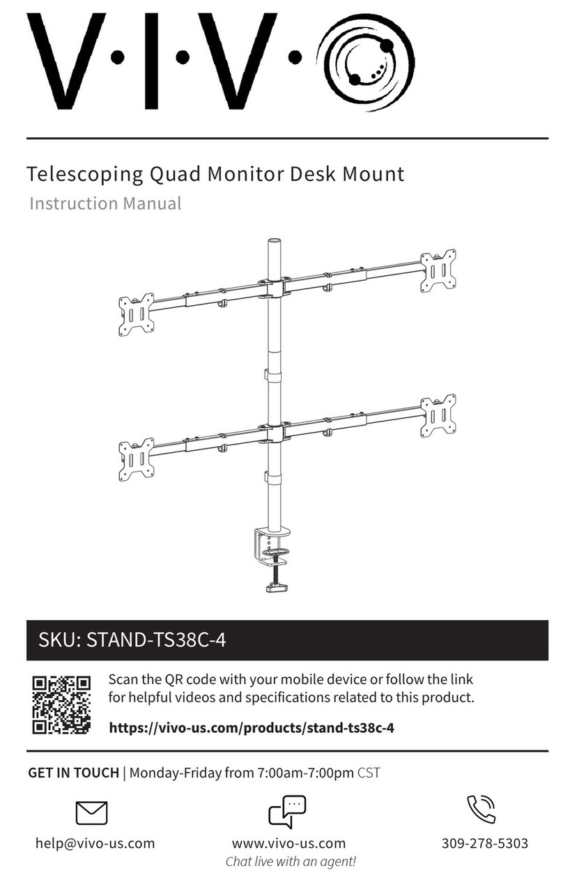
Vivo STAND-TS38C-4 instruction manual

Vivo

Vivo STAND-TS38C-4 instruction manual

Britec DRYERSTRAP Assembling instructions

Britec

Britec DRYERSTRAP Assembling instructions

PEERLESS SUT632P Installation and assembly

PEERLESS

PEERLESS SUT632P Installation and assembly

Snap One AN-920-SW-F-24-POE Regulatory compliance and safety information

Snap One

Snap One AN-920-SW-F-24-POE Regulatory compliance and safety information

Aruba AP-103H-MNT1 installation guide

Aruba

Aruba AP-103H-MNT1 installation guide

IBEX 10008367 Mounting instruction

IBEX

IBEX 10008367 Mounting instruction

Screen Innovations Solo installation instructions

Screen Innovations

Screen Innovations Solo installation instructions

Ergotron 60-604 user guide

Ergotron

Ergotron 60-604 user guide

ACME MTLM54 manual

ACME

ACME MTLM54 manual

Zaor Miza Rack 1 Series Assembly manual

Zaor

Zaor Miza Rack 1 Series Assembly manual

FONESTAR STV-676N instruction manual

FONESTAR

FONESTAR STV-676N instruction manual

Chauvet Professional DRB-F100CM Quick reference guide

Chauvet Professional

Chauvet Professional DRB-F100CM Quick reference guide

peerless-AV PLCM-1CP manual

peerless-AV

peerless-AV PLCM-1CP manual

manuals.online logo
manuals.online logoBrands
  • About & Mission
  • Contact us
  • Privacy Policy
  • Terms and Conditions

Copyright 2025 Manuals.Online. All Rights Reserved.