Vista Spyder 200 Series User manual

Vista
SYSTEMS
OPERATIONMANUAL
DocumentRevision:1.38
ReleaseDate:June2009
PartNumber:MAN‐SPYDER
VistaSystems,Corp.
2001W.MelindaLane
Phoenix,AZ85027
Phone:602.943.5700
Fax:623.582.3571
Web:http://www.vistasystems.net
Email:[email protected]
™

2
TableofContents
TableofContents............................................................................................................................2
Section1:ImportantSafetyInstructions........................................................................................5
CautionsandSafetyNotices.......................................................................................................6
FCCNotice‐ForCommercialUseOnly...................................................................................6
BatteryWarning......................................................................................................................6
ServiceWarning......................................................................................................................6
ClassIConstructionWarning..................................................................................................6
Operatingin110Vor220V..........................................................................................................7
Section2:SpyderHardwareFamily................................................................................................8
SpyderModelsandOptions......................................................................................................10
Spyder200Series.................................................................................................................10
Spyder300Series.................................................................................................................10
Inputs....................................................................................................................................11
Outputs.................................................................................................................................11
Options.................................................................................................................................12
PowerControl.......................................................................................................................14
Display...................................................................................................................................14
Section3:SpyderX20HardwareFamily.......................................................................................15
SpyderX20Models...................................................................................................................15
Inputs....................................................................................................................................18
Outputs.................................................................................................................................18
Power....................................................................................................................................18
FrontPanel............................................................................................................................19
Section4:ExternalControl............................................................................................................20
SerialConnectivity.....................................................................................................................20

3
EthernetConnectivity...............................................................................................................20
CommandProcessorResponses...............................................................................................22
SupportedCommandDescriptions...........................................................................................22
UnderstandingRegisters...........................................................................................................33
RegisterTypes.......................................................................................................................35
LayerAlignmentEffects............................................................................................................35
Section5:PhysicalSpecifications.................................................................................................38
Dimensions(WxHxD).............................................................................................................38
Weight.......................................................................................................................................38
PowerConsumption..................................................................................................................38
RackmountInstructions...........................................................................................................39

4
REVISIONHISTORY
DATEVERSIONCHANGEDESCRIPTION
07‐07‐20091.35ADDEDSPYDERX20INFORMATION
07‐15‐20091.36SMALLSPELLINGANDGRAMMATICALCHANGES
07‐21‐20091.37UPDATEDFCCCOMPLIANCESTATEMENT

5
Section1:ImportantSafetyInstructions
Thissymbolindicatesthepresenceof“dangerousvoltage”withintheproduct
enclosurethatmaybesignificantenoughtocauseariskofelectricalshock.
1. Readtheseinstructions.
2. Keeptheseinstructions.
3. Heedallwarnings.
4. Followallinstructions.
5. Donotusethisapparatusnearwater.Donotplaceobjectscontainingwaterontopof
orneartheunit.
6. Cleanonlywithadrycloth.
7. Donotblockanyventilationopenings.Installinaccordancewiththemanufacturer’s
instructions.
8. Donotinstallnearanyheatsourcessuchasradiators,heatregisters,stoves,orother
apparatus(includingamplifiers)thatproduceheat.
9. Donotdefeatthesafetypurposeofthepolarizedorgrounding–typeplug.Apolarized
plughastwobladeswithonewiderthantheother.Agroundingtypeplughastwo
bladesandathirdgroundingprong.Thewidebladeorthethirdprongisprovidedfor
yoursafety.Iftheprovidedplugdoesnotfitintoyouroutlet,consultanelectricianfor
replacementoftheobsoleteoutlet.
10. Protectthepowercordfrombeingwalkedonorpinchedparticularlyatplugs,
conveniencereceptaclesandthepointwheretheyexitfromtheapparatus.
11. Onlyuseattachments/accessoriesspecifiedbythemanufacturer.
12. Useonlywiththecart,stand,tripod,bracketortablespecifiedbythemanufactureror
soldwiththeapparatus.Whenacartisusedcautionwhenmovingthecart/apparatus
combinationtoavoidinjuryfromtip‐over.
13. Unplugtheapparatusduringlightningstormsorwhenunusedforlongperiodsoftime.
14. Referallservicingtoqualifiedservicepersonnel.Servicingisrequiredwhenthe
apparatushasbeendamagedinanywaysuchaspower‐supplycordorplugisdamaged,
liquidhasbeenspilledorobjectshavefallenintotheapparatus,theapparatushasbeen
exposedtorainormoisture,doesnotoperatenormallyorhasbeendropped.

6
CautionsandSafetyNotices
FCCNoticeForCommercialUseOnly
Thisdevicecomplieswithpart15oftheFCCrules.Operationissubjecttothefollowing2
conditions:(1)Thisdevicemaynotcauseharmfulinterference(2)Thisdevicemustacceptany
interferencereceived,includinganyinterferencethatmaycauseundesiredoperation.This
ClassAdigitalapparatuscomplieswithCanadianICES‐003.CetappareilnumériquedelaclasseA
estconformàlanormeNMB‐003duCanada.
BatteryWarning
ThebatteryinSpyderisnotintendedtobereplacedbytheuser.Failuretofollowthese
instructionswillvoidthewarrantyoftheunit.
Dangerofexplosionifbatteryisincorrectlyreplaced.
Replaceonlywiththesameorequivalenttypeofbattery.
ServiceWarning
Allservicinginstructionsareforusebyqualifiedservicepersonnelonly.Thereareno
procedures,exchange,orpartsthatareinsidetheunitthatareintendedtobeperformedbythe
user.Anyprocedureperformedinsidetheunitisintendedtobeperformedbyqualifiedservice
personnelonly.
Toreducetheriskofelectricalshock,theservicetechnicianshallremovethecordfromthewall
receptacleandtherearoftheunitbeforeattemptingtoservicetheunit.
Failuretofollowtheseinstructionsmayvoidthewarranty.
ClassIConstructionWarning
AnapparatuswithClassIconstructionshallbeconnectedtoaMAINSsocketoutletwitha
protectiveearthingconnection.
7
Operatingin110Vor220V
Spyder™shipsinthesettingpredeterminedbywhereitisshippingtobereadyforoperationout
ofthebox.ItcomeswithastickerovertheACinletnotingifitissetfor110Vor220V.If
operatingwithavoltageotherthanwhatitissetfor,afewchangesneedtobemade.
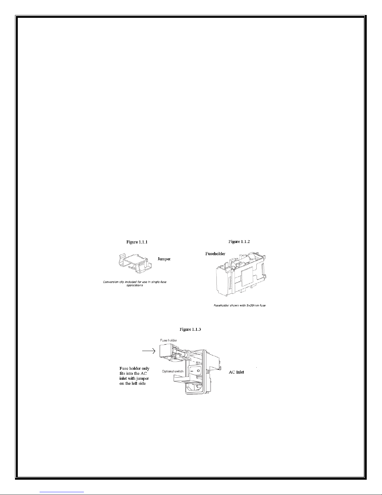
Tochangefrom110Vto220V:
1. Pullthefuseholder(Seefigure1.1.2)fromtheACinlet(Seefigure1.1.3).
2. Pullthejumperandcurrentfusefromthefuseholder.
3. Addfusesincludedwithshippingkit(2‐3Afusesfor3RUor2‐2Afusesfor2RU).Oneon
eachsideofthefuseholder.
4. InsertfuseholderbackintotheACinletandpowerup.Youarenowsetfor220V.
Tochangefrom220Vto110V:
1. Pullthefuseholder(Seefigure1.1.2)fromtheACinlet(Seefigure1.1.3).
2. Pullbothfusesfromthefuseholder
3. Addjumper(Seefigure1.1.1)ononesideoffuseholderandfuseontheothersidethat
isincludedwithshippingkit(1‐5Afusefor3RUor1‐3Afusefor2RU).
4. InsertfuseholderbackintotheACinletandpowerup.Youarenowsetfor110V.

8
Section2:SpyderHardwareFamily
Spyder™isacompactversatilevideoprocessingproductwithsuperbcapabilitiestoblend,
windowandscaleaverywidearrayofvideosignalswithunparallelqualityandease.
ThecompactmodulardesignallowsSpydertobeusedtodisplayavirtuallyendlessvarietyof
windowsthroughasingleoutput,orstretchasingleinputacrossmultipledisplaystocreatea
seamlesswidescreenimage,anddojustaboutanythingin‐between.
Spyderconsistsof2modelfamilies,the200and300series,eachfamilyhasmultiple
configurationsavailabletomeetthemostdemandingenvironmentandallmodelshave
expansionability(optional)toprovidemoreinputs/windowsormoreoutput/displaysorboth.
Spydercontrolcanbeaccomplishedmultiplewaysdependingonapplication:
•SpydercontrolsuitePCbasedsoftwareapplications
•HardwarebasedVistacontrollers
•3rdpartycontrolsystemssuchasCrestronorAMX
ThismanualisdesignedtogiveanoverviewofSpyderfeatures,functionalityandoperation.The
detailedoperationofwillbefoundintherespectivemanualsforeachindividualcontrol
platform.

9
10
SpyderModelsandOptions
Spyder200Series
The200seriesisa2RUunitthatutilizes4I/Omodules.
Asampleofvalidconfigurationsislistedbelow.
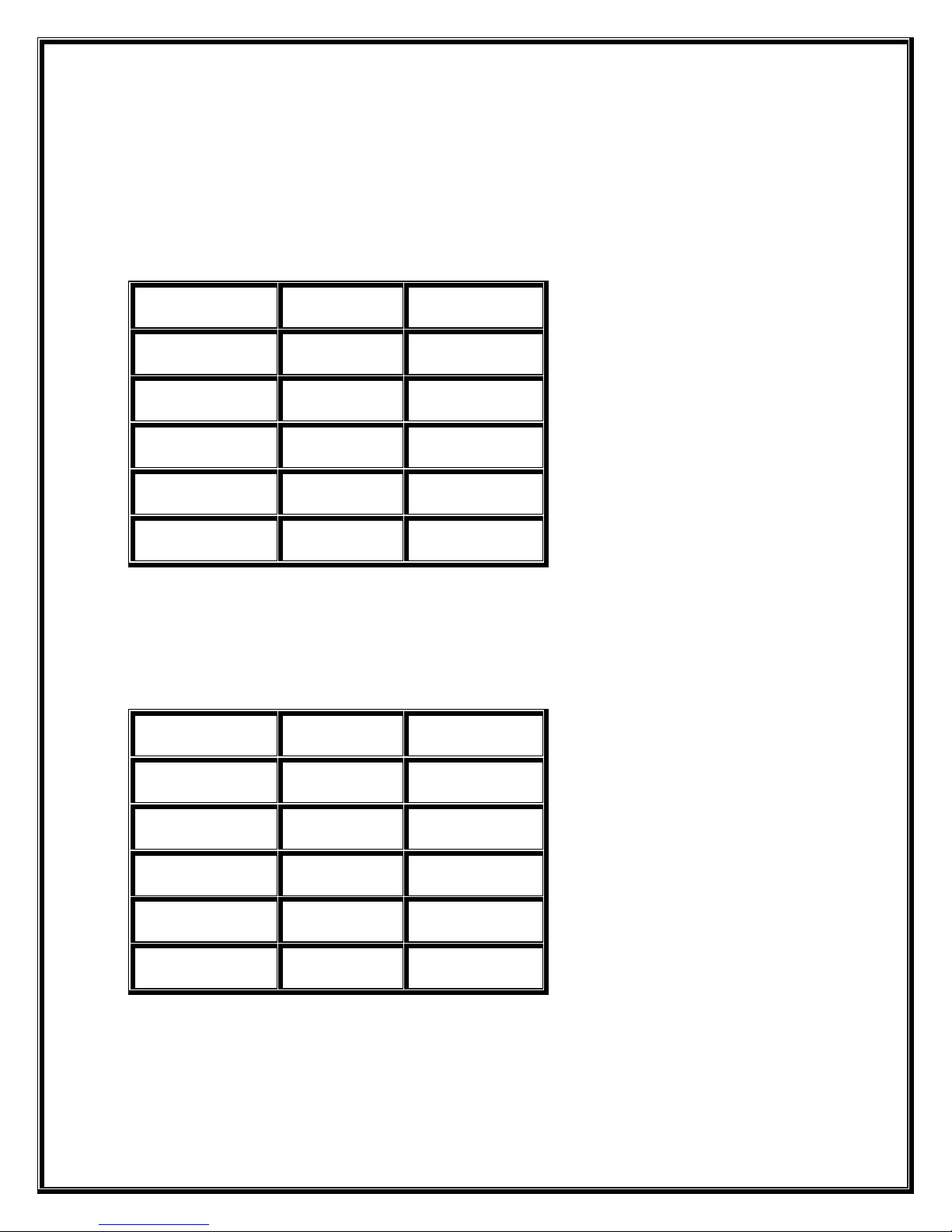
ModelNumberNo.ofInputsNo.ofOutputs
240*40
204*04
22222
21313
23131
Spyder300Series
The300seriesisa3RUunitthatutilizes8I/Omodules.
Asampleofvalidconfigurationsislistedbelow.
ModelNumberNo.ofInputsNo.ofOutputs
380*80
308*08
34444
35353
36262
*Thesemodelsavailableonlywithcontrolexpansionoption.Fixedcontrolversionsnot
available.
11
Inputs
BelowarelistedthestandardvideoformatsacceptedbySpyder
•24p,NTSC,PAL,andSECAM
•AnalogRGB(SOG,CompositeorSeparateSync)
•AnalogYUV
•SDI
•HD‐SDI
•DVI‐SingleLink
oDVI‐DualLink
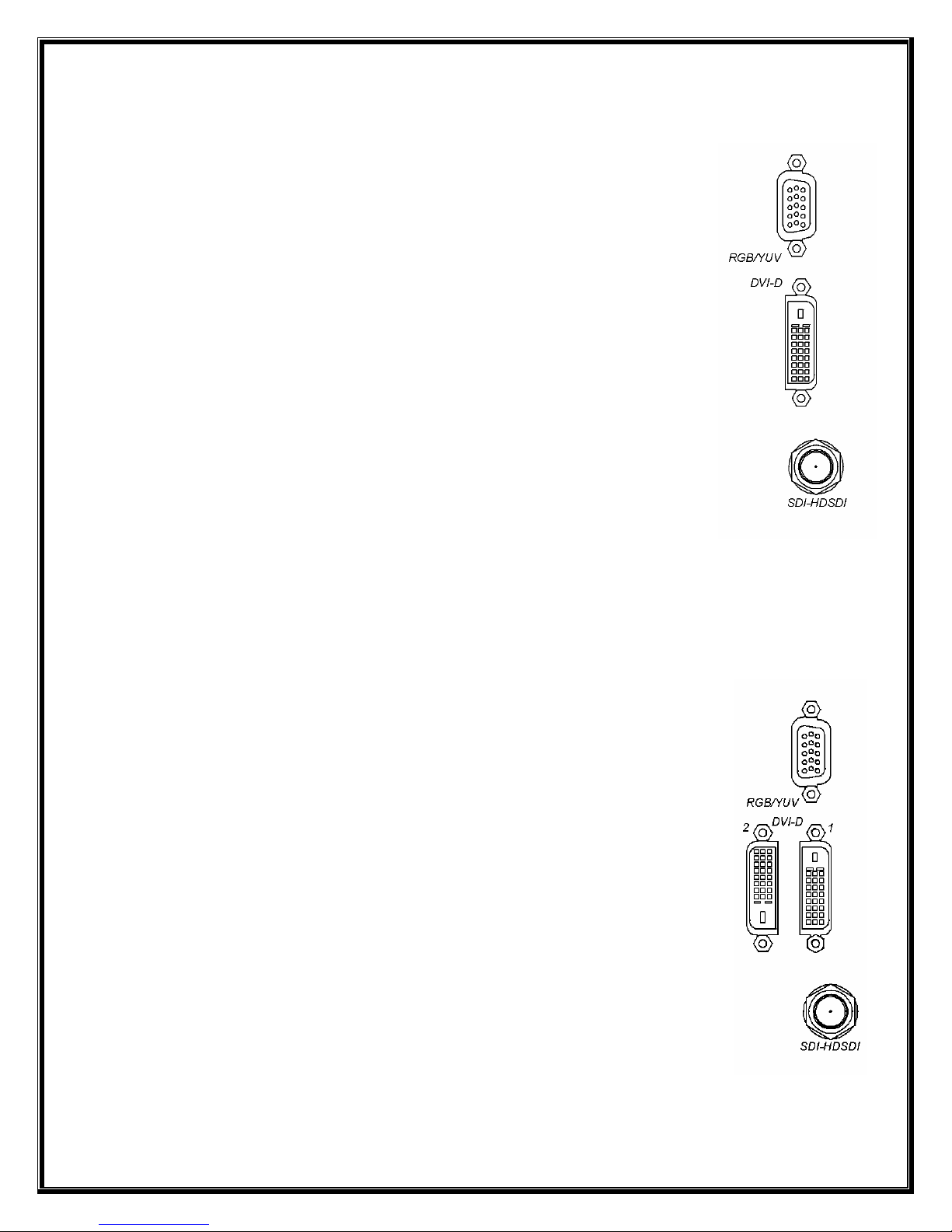
Eachinputmodulehasasingleinputconnectorforthesupportedsignaltypes:
•ANALOG
•SDI/HD‐SDI
•DVI
•CompositeandS‐Video(Comp/S‐VidOptional)
Eachinputisuniversal:aninputcanbedynamicallyassignedandusedasamixer,amixer,ora
key.Thesesettingsarealsoaccomplishedfromthechosencontroltype.
Outputs
EachOutputModulehasvariousvideoconnectorsontherear.Conditionsexist
whenmultipleoutputtypescanbeutilized.
BelowarelistedthestandardvideoformatsacceptedbySpyder
•24p,NTSC,PAL,andSECAM
•AnalogRGB(SOG,CompositeorSeparateSync)
•AnalogYUV
•SDI
•HD‐SDI
•(2)DVI‐SingleLink
•(2)DVI‐DualLink
oDVITwinLink
Eachoutputmodulehasasingleconnectorforthesupportedsignaltypes:
•ANALOG
•SDI/HD‐SDI

12
•DVI
•DVI–Dual
•CompositeandS‐Video(Comp/S‐VidOptional)
Multipleoutputconnectortypescanbeusedsimultaneously,providedthatthevideoformatis
validforthespecificvideoconnections.Belowareafewexamples.
•DVI&Analog:WhenanoutputisconfiguredforNon‐InterlacedComputerSignals
•SDI&Analog:Whenconfiguredfor480i/575i
•HD‐SDI&Analog:Whenconfiguredfor1080i
Options
Spyderoptionslistedbelowareavailableoneither200or300Seriesproducts.
Existingunitscanberetrofittedonceshippedbutmustbereturnedtothefactoryforanyof
theseprocedures.
200X/300XExpansionOption
AllowsmultipleunitstobeconnectedtogethertoexpandInputs,Outputsorboth.(SeeFigure
3.3.1bonfollowingpage)
InfiniBandCable(VistaP/NCAB‐60670)
ThiscableallowsmultipleSpyderunitstobeconnectedtotheExpansionPorts.Thisoptionis
onlyapplicablewiththe200Xor300XOption.
200C/300C(Composite/SVideoOption)
WhenselectedthisoptionwillprovideComposite(BNC)andS‐Video
(SVHS)connectionsoneachInputandeachOutputoftheSpyderunit.

13

14
PowerControl
TheSpyderusesasoftpowerscheme.PressingtheStandbyswitchinitiatesapowerupcycle
andafterashortboottimethefrontpaneldisplaywillindicateoperationalstatus.Pressingthe
Standbyswitchagaininitiatesthepowerdowncycleafterwhichtheunitentersstandbymode.
ThereisahardpowerswitchontherearthatshouldbeusedonlywhenSpyderisinthestandby
state(StandbySwitchLEDisoff).
Theusershouldavoiddisconnectingtheprimarypowersource(ACinput)untilthe
unitisinstandbymode.Failuretodothiscouldresultinharddrivedatacorruption.
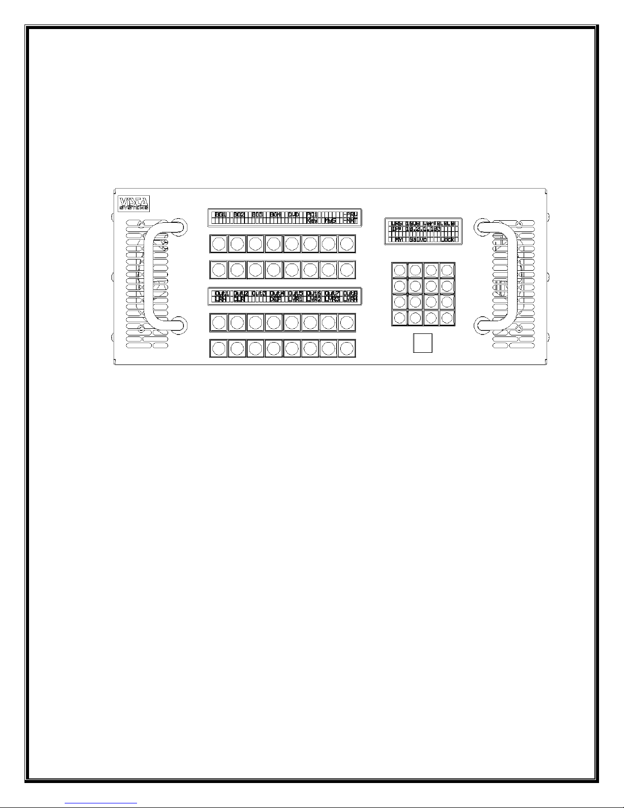
Display
TheSpyderenclosureisequippedwithastatus/errordisplaylocatedonthefrontpanel.Thisis
helpfulindeterminingproperstart‐upandshut‐downoftheunit,aswellasindicatingerror
messages.Thefollowingdiagramindicatesthestatuswhentheunithasbeenbootedupandhas
determinedtheversion,frame,I/OconfigurationandIPaddress.

15
Section3:SpyderX20HardwareFamily
SpyderX20™isasecondgenerationSpyderhardwareline.X20increasesboththeI/Ocapacity
andvirtualimagespace(VI)availablewithinasinglechassis,makingapowerfulandcost‐
effectivesolutionformid‐rangeSpyderconfigurations.
SpyderX20Models
SpyderX20usesamodularchassisdesign,whichcanbepopulatedatthefactorywithvarious
combinationsofinputandoutputchannelsasrequired.Availablechassissizesstartatthree‐
slotconfigurations.
Notethatnotallslotsmustbefilledinachassis;alargerchassiswilloperatewithoutallslots
beingfilled.Thismakesaneasyhardwareupgradepathforsystemsthatmayneedtoincrease
capacityovertime.
16
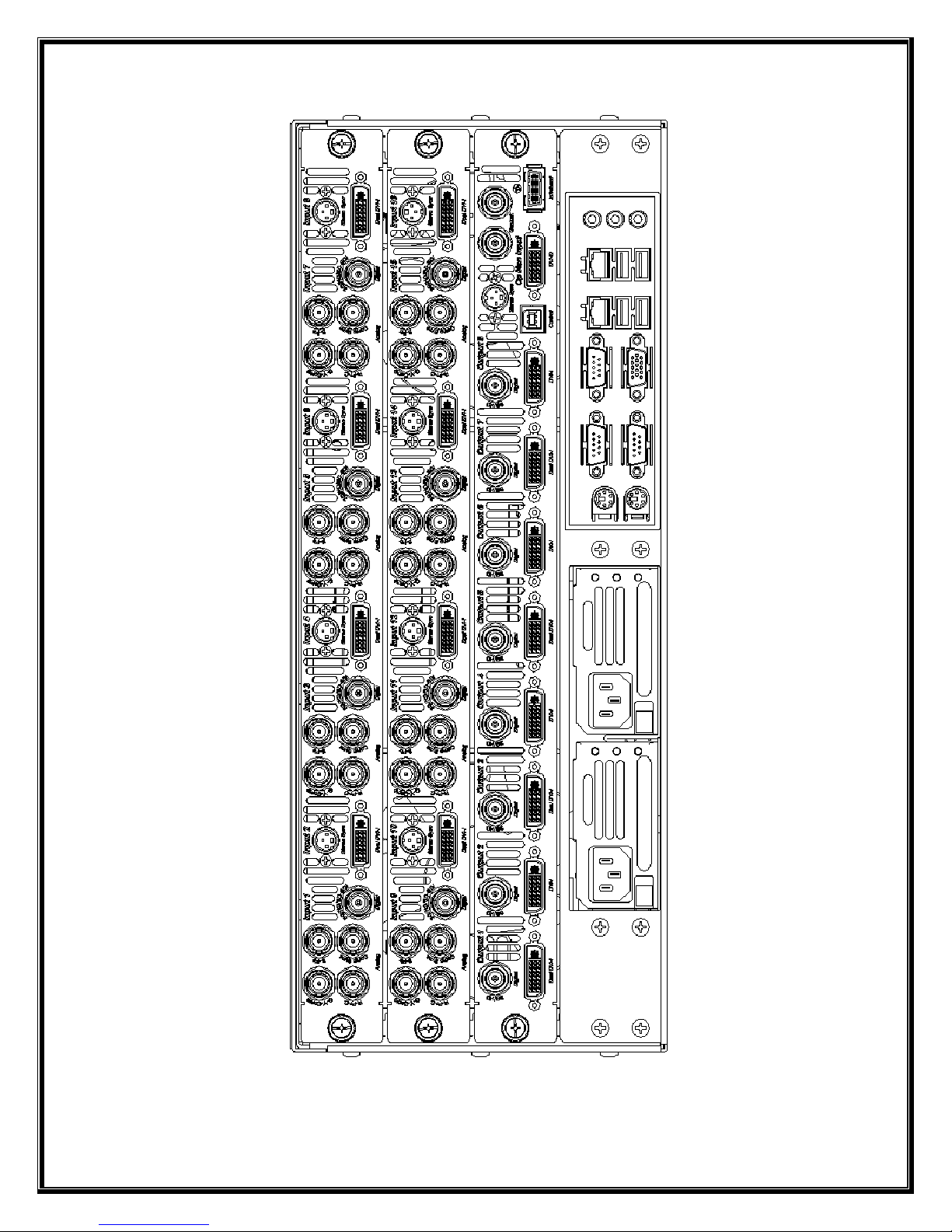
Figure1:X201608BackPanel

17
Figure2:X20FrontPanel

18
Inputs
Theconnectortypesalternateoneachinputconnectorformaximumflexibility,andthespecific
connectortypesarelistedbelow.Foreachinput,onlyoneconnector/signaltypecanbe
selectedatatime.
OddInputConnectors(1,3,5,etc.)
•Analog(3or4wireBNC)
•Composite/S‐Video(SharesBNCwithcompositeanalogsyncsignal)
•SDI/HD‐SDI/3G‐SDI(SinglededicatedBNC)
EvenInputConnectors(2,4,6,etc.)
•DVI‐I(AnalogandDigitalonsingleconnector)
•StereoSyncinput(3‐PinDIN)
Outputs
EachOutputModulehasvariousvideoconnectorsontherear.Multipleoutputconnectorscan
beenabledsimultaneously,providedthattheuserdefinedoutputformatisvalidforthe
connector.SXGA(1280x1024)forexample,isvalidforDVIandanalogconnectors,butisnota
validformatforSDI,composite,orS‐Videoconnectors.
Eachoutputchannelprovidesthefollowingconnectortypes:
•DVI‐I(AnalogandDigitalonsingleconnector)
•SDI/HD‐SDI/3G‐SDI
Power
TheX20usesasoftpowerscheme.PressingtheStandbyswitchinitiatesapowerupcycleand
afterashortboottimethefrontpaneldisplaywillindicateoperationalstatus.Pressingthe
Standbyswitchagaininitiatesthepowerdowncycleafterwhichtheunitentersstandbymode.
Holdingthepowerbuttononthefrontpanelofthesystemfor13‐15secondscanbeusedto
forcepoweroff,howeverthistechniquemaycausepermanentconfigurationdataloss.
Theusershouldavoiddisconnectingtheprimarypowersource(ACinput)untilthe
unitisinstandbymode.Failuretodothiscouldresultinharddrivedatacorruption.
19
FrontPanel
TheX20enclosureisequippedwithaLCD/switchbuttoninterfacelocatedonthefrontpanel.
Thisinterfaceallowsforbothcontrolandaccesstostatusinformationoftheunit.Asthefront
panelfunctionalityisdependentontheversionoffirmwarerunningontheunit,actualfront
paneloperationisdiscussedindetailinthesoftware/operator’smanualfortheX20.
20
Section4:ExternalControl
TheSpyderframeusesanASCIIbasedcommandsystemforexternalcontrol.Connectivityis
availableviaanRJ‐45(Ethernet)connection,ora9‐pinRS‐232serialconnectiontotheframe.
BoththeEthernetandSerialinterfacesrespondtothesamestringcommands,andcandoso
concurrently.
SerialConnectivity
OneofthethreeRS‐232serialportsavailableonthebackofthe
Spyderframecanbeconfiguredtoacceptexternalcontrol
commandsbyusingtheVistaBasicorVistaAdvanceduser
interface.Seethesoftwareoperation’smanualformore
informationonconfiguringSpyderforexternalcontrol.
Note:Whenusingserialcontrol,eachcommandmustbe
terminatedwithacarriagereturn.
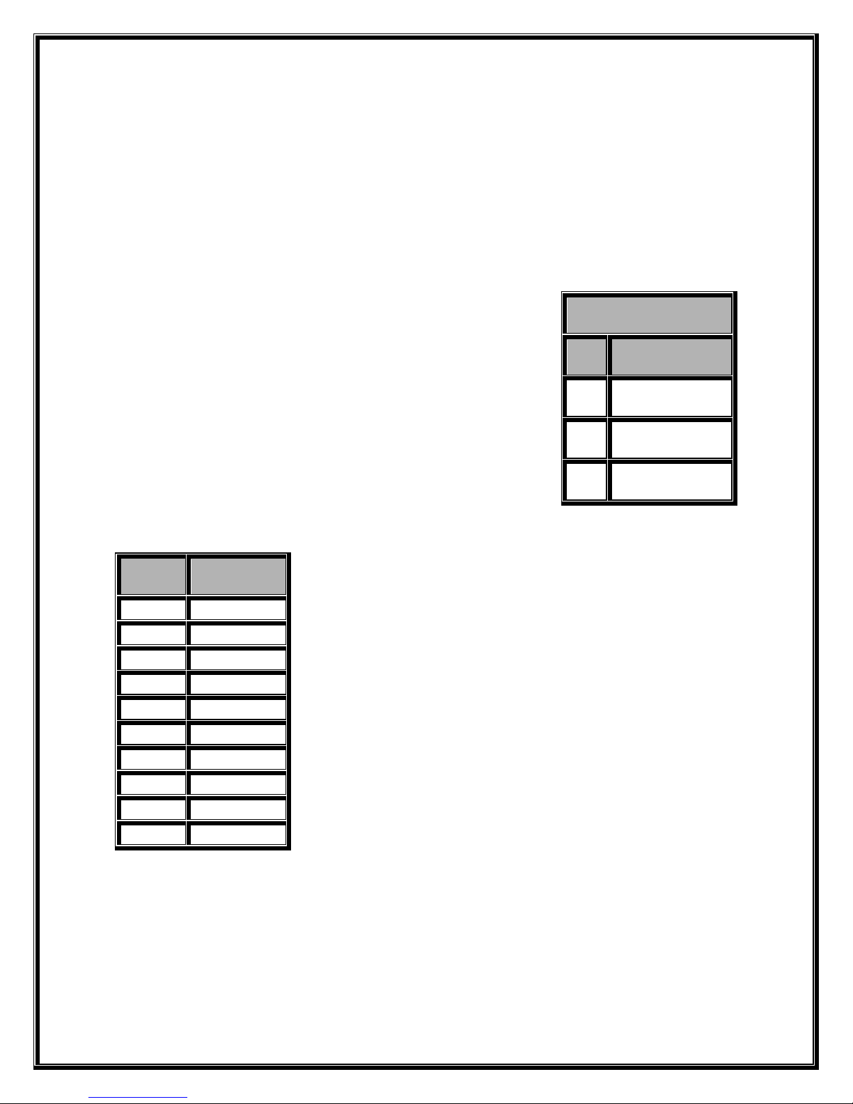
EthernetConnectivity
TheSpyderframecanbecontrolledremotelybysendingtheASCII
commandslistedbelowwithinaUDPpacketsenttoport11116on
theframe;noconfigurationisrequired.Eachmessagesentto
SpyderoverUDPmustbeprecludedbya10bytemessageheader.
Thisheaderisshowntotheleftofthisparagraph.
Note:Donotputanargumentdelimiter(spacecharacter)between
theheaderandtheexternalcontrolcommand.
Note:Commandsandargumentsaredelineatedbyasinglespace
character.
RS‐232SerialPinout
PinFunction
2Receive(RX)
3Transmit(TX)
5Ground
IndexCharacter
0s
1p
2y
3d
4e
5r
60x00(hex)
70x00(hex)
80x00(hex)
90x00(hex)
This manual suits for next models
2
Table of contents
Other Vista DVD Player manuals


