VistaPure 3000 User manual
Ultra Pure Water System
Model 3000
Installation Guide
& Owner’s Manual
The VistaPure Ultra Pure Water System is designed
to produce two grades of high-purity water – 1) distilled-
quality for use in your autoclaves and 2) non-corrosive water
for use in bottle systems and for other uses. It is critical that
water used in autoclaves be virtually free of dissolved solids
and contaminants in order to protect the heating chamber
and to prevent build-up of contaminants that can create hard
deposits and more frequent cleanings. If poor quality water
is used, the autoclave will generally need to be re-built or
replaced at substantial cost. Water used in self-contained
dental bottle systems should be of high quality but not the
same grade as used in autoclaves since distilled-grade water
is corrosive to metals used in the construction of dental
units. The VistaPure system is designed to be built-in to
sterilization centers, cabinetry or can be simply installed in
an equipment room. In addition to use with your autoclaves,
the high purity water produced by your new VistaPure can
be used for making coffee, tea and other beverages, for
laboratory use and more.
The system provides 2.7 gallons of treated water in the
pressurized storage tank and automatically produces a new
supply as water is drawn from storage. The system does
not require electricity – it only needs a potable supply of
cold water and a drain. It is highly recommended that water
supplied to the system be free of sediment. Further, if the
source water is hard, the system ltration elements will last
longer if the water supply is softened.
Although actual installation of VistaPure is quite simple, it
is recommended that a professional technician familiar with
dental operatory systems perform the installation due to the
wide variety of possible options, running of water and air
lines, drain lines, etc. He/she should be familiar with the
local plumbing codes and techniques for successful dental
equipment installations.
Please read this entire manual before proceeding with
installation and operation.
Please make certain that anyone responsible for future
operation and maintenance of the system is familiar with
all details contained in the installation and maintenance
manuals.
Please keep the maintenance manual handy for
future reference.
Please return the Warranty / Registration form
immediately upon installation.
Always follow local plumbing codes.
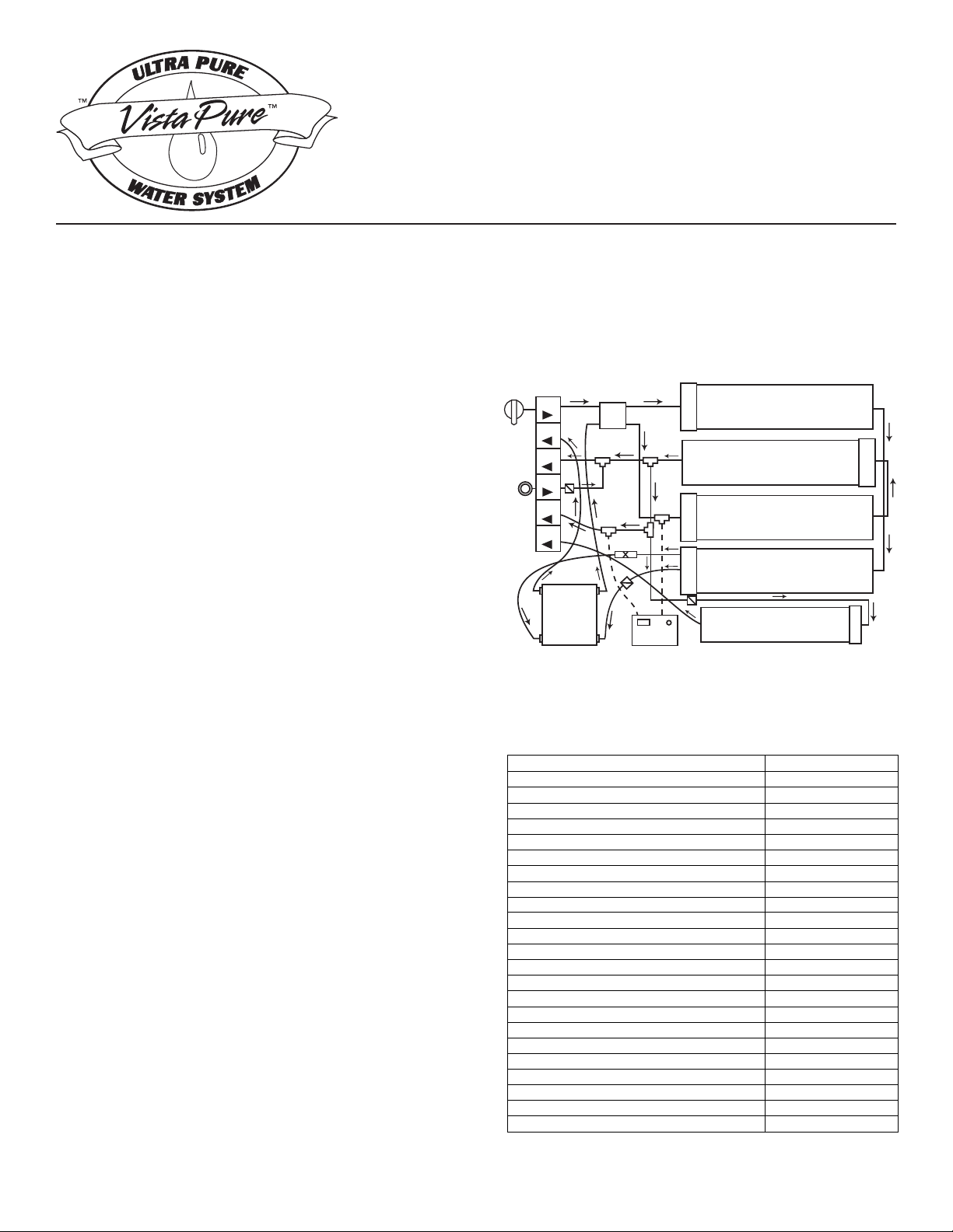
Note the following specications before proceeding:
Prefilter
D/I #2
D/I #1
Hyperfiltration
Polishing
1
3
2
5
C
H
B
101
102
103
104
105
106
A
K
I
4
Figure 1. Front view of the VistaPure system.
VistaPure Model 3000 Specications
Maximum Operating Temperature 100°F
Minimum Operating Temperature 45°F
isp001erusserPgnitarepOmumixaM
tsebisp+04–isp03erusserPmuminiM
5.8–5.6egnaRHplamitpO
Maximum Total Dissolved Solids (TDS) 500
5.9–5.5egnaRHpmumixaM
mpp171/rg01ssendraHtneulfnImumixaM
mpp50.0esenagnaMtneulfnImumixaM
mpp1.0norItneulfnImumixaM
Maximum Influent Hydrogen Sulfide none
Maximum Influent Chlorine/Chloramine 2 ppm
Maximum Daily Output (12 hours) 25 gal (94 L)
Stage 1 Prefiltration Element Service Life 1 year max
Stage 1 Prefiltration Replacement Order # R5633
Stage 2 Hyperfiltration Element Service Life 3-5 years
Stage 2 Hyperfiltration Replacement Order # R3080
Stage 3 Deionization Element Service Life 4-18 mo – See pg 7
Stage 3 Deionization Replacement Order # R5662
Stage 4 Polishing Filter Element Service Life 1 year max
Stage 4 Polishing Replacement Order # R2551
System Dimensions (W x H x D) 22”x16”x 5”
”61x”5.9)HxaiD(snoisnemiDknaT
Approximate Shipping Weight (Dry-2 Cartons) 33 lbs

UNPACKING – Carefully unpack the contents of
the product carton. It should include the system,
Installation Guide & Owner’s Manual, Warranty
Registration sheet, an accessory pack and a supply
of colored tubing. Check to make certain there was
no damage during shipment. If damage is evident,
contact the shipping company or your distributor
immediately.
DATA – Locate the serial tag on the system and record
it on the blue Warranty Registration sheet. Provide
all of the information requested on the Warranty
Registration sheet and mail it immediately to Vista
Research Group, LLC upon installation. Write the
date of installation and the installer’s name on the tag
using a ne tip, permanent marker (e.g. a Sharpie®)
or some other writing instrument that will not smear.
HOW THE SYSTEM WORKS – The system is a
unique design that combines several technologies
using multiple stages to produce the highest purity
product – water with a total dissolved solids (TDS)
reading as low as zero (000).
The rst stage is a Prelter that removes sediment,
chlorine and other contaminants by physical ltration,
absorption and adsorption. Next is the Hyperltration
stage where pressure from the water source and the
non-electric permeate pump forces the water through
a semi-permeable membrane removing contaminants
at the molecular level. Contaminants are rinsed away
from the membrane and down the drain. The water
is then sent to two cartridges in series that contains
both cationic and anionic resins for removing any
remaining contaminants by a Deionization process.
The nished water is sent to a 2.7 gallon storage tank
where it is delivered on demand to the autoclave ller
wand or the bottle faucet as needed. Water running
to the secondary faucet (for lling bottles, etc.) runs
through the Polishing lter after leaving the tank
where a small amount of dissolved solids is added
back to the water to prevent corrosion.
LOCATION: The VistaPure system can be installed
nearly anywhere in the typical dental, medical, lab or
hospital setting, typically near a faucet and sink. The
system and tank are designed to t under a countertop
and connect directly to the cold water supply line and
drain. It may also be installed in any area where there
is a quality cold water supply and drain connection.
INSTALLATION: Although actual installation of
VistaPure is quite simple, you may wish to enlist the
services of a professional technician since your system
is going to be directly connected to the plumbing
system. He/she is familiar with the wide variety of
possible installation options, running of water and
drain lines, local plumbing codes and techniques for
successful equipment installations.
Installation Procedure
( Please refer to drawings that follow )
1. If the system is not already mounted in another
product (sterilization center, etc.) mount as desired
near a cold water source and 1-1/2” drain.
2. Position storage tank as near VistaPure system
board as possible.
3. Locate the white elbow tank valve in accessory
pack and attach valve to the side of the tank. Hand-
tighten only!! Never use tools on system valves and
ttings!
4. Provide for a 1/4” connection to the cold water
supply. This is usually done using a piercing saddle
valve or compression tting.
5. Provide a 1-1/2” vertical drain riser with trap as
shown in Figure 3 or Figure 4. The Air Gap drain
tting and 1/4” push-type tting is included in the
accessory pack. The Air Gap drain tting should be
glued to the drain riser as shown. See page 6 for drain
congurations.
6. Mount the faucet on the sink or countertop deck.
The faucet & push-type faucet connector tting are
included in the accessory kit.
7. Attach colored tubing to the proper segments on the
system manifold and the appliance/device as shown
in Figure 2. When attaching tubing to the push-type
ttings, make certain all tubing cuts are straight and
free from burrs. Tubing must be rmly inserted into
the tting (11/16” plunge) to avoid leaks.
IMPORTANT NOTE: If the system is mounted
inside a cabinet, under a sink or on a sliding device,
be careful that tubes are not crushed or crimped. If
the system is on a sliding device for easy access,
make certain to create a coil with the tubes that will
allow the system to move in and out without causing
damage or restriction. See Figure 7 for the proper
coil layout.
IMPORTANT NOTE: If the VistaPure system is
to be installed remote to the autoclave(s) and/or in a
cabinet, sh the solid blue tubing behind cabinetry
to the autoclave center. The solid blue tubing and
the coiled blue tubing are to be joined with the white
1/4” x 3/8” push-type union that is already attached
to one end of the coiled tubing. Please see Figure 2.
Make certain to provide a restraint at the straight
end of the coiled tubing near the union so that when
pulling out on the autoclave wand and coiled tubing
the union connection is not stressed.
2

Extra lengths of tubing are included with each system.
Below is the tubing color code chart. Please refer to
Figure 2 for detail.
Red From Cold Water Supply
Black To Drain
Natural To and From Tank
Blue Smooth To Autoclave Area
Blue Coiled To Autoclave Filler Wand
White To Faucet
8. Cleansing the system (after all tubing connections
have been made). Find the 35 ml syringe that’s
included in the accessory kit. Place about 20-30 ml
of clean water into a small paper cup and add about
two (2) drops of standard household bleach. Stir
gently with the syringe then pull the solution into the
syringe. Remove the safety cap from the injection
port at “K” on the manifold (see Figure 2). To remove
the cap simply hold the collet back against the cap
tting and pull it away from the check valve. Inject
the solution into the Injection Port. Draw 20-30 ml of
fresh water into the syringe and also inject it into the
Port in order to push all the bleach out of the check
valve. Replace the safety cap by pushing it rmly
onto the Injection Port tube. Immediately “Open”
the Water Supply Inlet Valve “I” on the manifold and
water will begin to ow into the system lling the
tank with treated water and the bleach.
9. Allow the system to run for twenty (20) minutes.
Waste water should be running to the drain Air Gap
“D” and a pulsing / clicking sound should be heard
coming from the Permeate Pump “C.” After twenty
minutes, “Close” the Water Supply Inlet Valve “I”
on the system manifold then discharge water from
both the Autoclave Wand “F” and Faucet “G” until
Tank “E” is empty and water ow stops. The system
is now cleansed.
10. “Open” Water Supply Inlet Valve “I” and allow
it ro run until the tank is full. This will take over an
hour for the tank to completely ll. However, water
can be used anytime after about thirty minutes since
the system produces and stores up to 2.7 gallons of
water and can deliver water to both the Wand and
the Faucet even while it’s making new water. The
system capacity is about 25 gallons of production per
12 hour work day.
Monitoring TDS
Total dissolved solids (TDS) is the quantitative
measure of virtually ALL constituents found in a
particular water supply counted as parts per million
(ppm) or milligrams per liter (mg/l). Water is simply
H2O – basically, everything else found in it would
contribute to the TDS. A typical city water supply will
have a TDS reading of from 150 – 350 TDS, although
it varies greatly. The federal standard for municipal
water systems is a maximum of 500 ppm TDS. Some
rural well waters are quite often found to range from
300 to over 1,000 ppm. Water for use in autoclaves
should be of distilled quality which is a TDS of 0 – 5
ppm (some more sensitive autoclaves require 0 – 3
ppm). Water with TDS readings higher than 5 ppm
will eventually cause staining, scale build-up, etc. and
require cleaning and/or repair. The worse the water,
the more costly the maintenance and repairs – to the
point that some autoclaves won’t even operate if the
TDS is high.
The VistaPure system comes equipped with a battery-
operated dual TDS meter. This allows you to check
the water quality throughout the system. For example,
slide the switch on the TDS meter (see Figure 5)
to “IN.” This reads the level of TDS in the water
emerging from the Hyperltration module. Slide the
switch to “OUT” and this will display the level of TDS
emerging from the Deionization modules on its way
to the Tank and/or Autoclave Wand. Water should be
running during test.
A separate handheld TDS meter is also included that
can be used to determine the level of TDS in the
Supply Water fed to the system. With these data one
can monitor the complete process as necessary. For
example, under normal operating conditions, typical
TDS levels might be as follows in this example:
City Water Feed 200 TDS X
After Hyperltration 010 TDS 5% of X
After Deionization 000 TDS After D/I
Remember, this is only an example. However, the
reading on the “IN” should generally be about 5% of
the inbound water TDS and the D/I modules remove
the balance remaining to achieve the 0-3 TDS level
desired.
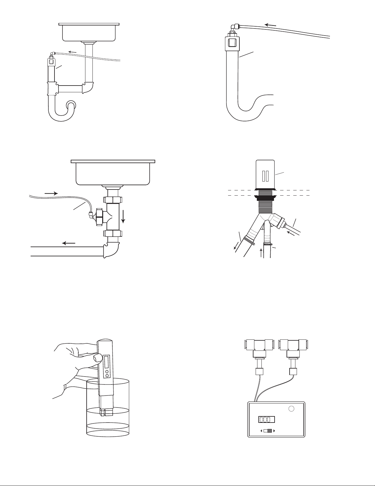
Figure 7 shows the handheld TDS monitor provided
with your system. It can be used at any time to
determine the quality of the raw and treated water.
Simply remove it from the leather case, remove the
protective cap exposing the probe, push the power
button to activate, immerse the probe into the water.
The LCD display will show the TDS level. NEVER
immerse the monitor beyond the rst section
(marked as “A” on Figure 5). While immersed, the
“hold” button can be pushed to lock the display. After
use, shake the water out of the probe area and wipe the
outer portion dry – never push anything into the probe
area. Check the water quality frequently and change
lter elements as required (see the Specications on
cover for replacement frequency). Both TDS monitors
are operated by a simple button cell battery available
at most any store.
3

VistaPure Ultra Pure Water System
MODEL 3000
Block Flow Diagram Legend
A = System Manifold
101 = City Water “IN” To Prelter
102 = To Drain From Permeate Pump
103 = To Water Storage Tank From D/I #2
104 = Injection Port To Tank Line
105 = To Autoclave Filler Wand From D/I # 2 and/or Tank
106 = To Bottle / Drinking Water Faucet From Polishing Filter
B= Automatic Shut-Off Valve
C = Permeate Pump
D = Air Gap Drain Fitting
E = 2.7 Gallon Water Storage Tank
F= Autoclave Filler Wand
G = Lead-Free Bottle-Filling / Drinking Faucet
H = Dual Total Dissolved Solids (TDS) Monitor
I = System Water Shut-Off Valve
J = Water Storage Tank Shut-Off Valve
K = Injection Port Assembly
= Flow Restrictor
= Check Valve
= DC Current Lines to TDS Meter
= 3/8” O.D. x 1/4” I.D. Coiled Water Tubing
P.O. Box 321 • Ashland • OH • 44805-0321
© 2005-2006 VRGLLC Version: 07/19/06
Vista Research Group, LLC
4

VistaPure Ultra Pure Water System
Model 3000
2005-2006 VRGLLC
c
Figure 2. Complete block diagram of the VistaPure Model 3000 system.
The numbers 1-5 in the right hand corner of the filter elements indicate
the order of flow for treatment. The first stage (1) is the Prefilter, etc. Version: 07/19/06
Polishing
C
H
B
101
102
103
104
105
106
A
K
I
D
EJ
F
G
From H20
Supply
Red
Black
Natural
Blue Coiled
Blue
White
Prefilter
D/I #2
D/I #1
Hyperfiltration
1
3
2
5
4
Vista Research Group, LLC
5
DUAL TDS METER
ON/OFF
PPM
IN OUT
IN OUT
Figure 7. Handheld TDS monitor. Figure 8. Mounted dual TDS monitor.
Drain Line
from VistaPure
Drain Line from
Instrument Washer
Drain Line
from VistaPure
To Branch
Tailpiece
Countertop
Airgap above
Flood Rim
Drain Line
from VistaPure
1-1/2”
w/ Trap
Figure 5. Typical installation of drain Tee (S9146) using
existing sink drain system. Order separately.
Figure 6. Typical installation of dual inlet drain Air Gap
system (S9147) using branch tailpiece. Order separately.
1-1/2”
w/ Trap Drain Line
from VistaPure
Figure 3. Typical installation of drain Air Gap (S9145)
using existing sink drain system.
Figure 4. Typical installation of drain Air Gap (S9145)
using separate riser and trap.
Note: Figures 3 & 4 show drain configurations using the air gap drain fitting included with the VistaPure system
on a 1-1/2" drain riser. Local codes vary greatly and other drain connection options are shown above. Every
VistaPure has multiple check valves in the system to prevent backflow from drain connections.
6

Filter Performance Record
Date
“A”
Water Supply to
System
(Use handheld TDS
Meter )
“B”
After
Hyperfiltration
(Use mounted
Meter “IN”)
“C”
Percent TDS
remaining
(Divide column
B by column A)
“D”
TDS after D/I
(Use mounted
meter “OUT”)
Water at
Autoclave Wand
(Use handheld
TDS Meter )
Water at Faucet
(Use handheld
TDS Meter )
NOTE 1: Record the TDS level in each column above monthly to determine water quality. First make a copy of
the blank table before recording so you’ll have a blank master for future years. When the percent remaining
in column “C” above goes above 10%, it is time to purchase and change the Hyperltration element R3080. This
element should last 3-5 years between changes under normal conditions.
NOTE 2: The Prelter element R5633 and Polishing element R2551should be changed about once each year.
NOTE 3: When the number in column “D” above goes above 2 TDS, it is time to purchase and change BOTH of
the D/I elements. Note the ow directions of the D/I #1 and D/I #2 elements, remove them and throw them away.
Both D/I lter elements are identical but ow in different directions. Simply orient the elements in the proper ow
direction.
NOTE 4: Water should be running through the system for accurate results when checking water quality using the
system mounted TDS meter. Simply run the VistaPure faucet for a few moments and the system will start to pro-
duce water. Water will then be owing through the probe “Tees” and yield accurate testing results.
**** WARNING ****
NEVER attempt to change any lter elements with pressure on the system! Follow these steps when changing
elements:
1. Turn “OFF” Water Inlet Supply “I”
2. Close Tank Valve “J”
3. Discharge Autoclave Wand “F” and Faucet “G” to relieve all pressure
4. After elements are changed, perform a system cleansing by following Step # 8 of the Installation
Instructions at least once per year and anytime a lter element is changed.
7

Filter Replacement Record
R5633
Prefilter
R3080
Hyperfiltration
R5662
Deionization
R2551
Polishing
NOTE: Record the date of each element change in the table above. First make a copy of the blank table be-
fore recording so you’ll have a blank master for future years.
Prefilter
D/I #2
D/I #1
Hyperfiltration
Polishing
101
102
103
104
105
106
Red
Black
Natural
Blue
White
Figure 9. Complete block diagram of the VistaPure Model 3000 system showing tubing coil loop that allows the
system to slide in and out of cabinetry. Note suggested wire ties on tubing loop.
WARNING: Turn the valves on the water inlet (I) and tank (J) “OFF” at the end of each day to prevent water
damage should a leak occur when staff is not present. Although the system components are all tested to high
pressures, water hammer and higher nighttime water pressure could potentially create a leak that might cause
property damage. Make it a standard practice to turn valves (I) and (J) “ON” each morning and “OFF” each eve-
ning. If the system is connected to a solenoid shut down system for the water line feeding the inlet, only the tank
valve (J) needs to be turned “OFF.”
NOTE: Please make certain the installers, users and persons maintaining the VistaPure system read this manual
and the enclosed “Special Notes, Warnings & Reminders” page for requirements and to assure best system
performance.
© 2005-2006 VRG, LLC IG-3000-4
Vista Research Group, LLC
P.O. Box 321 Ashland Ohio 44805-0321
419.281.3927 PH 419.281.7380 FX
vistaresearchgroup.com [email protected]
Table of contents
Popular Water System manuals by other brands

Westomatic
Westomatic HYDRATION STATION Installation & maintenance guide

Charger
Charger WS1-CD Quick start manual

AmeriWater
AmeriWater 00M10800 manual

Real Spirit
Real Spirit AIR WATER LIFE Aqua Ionizer Deluxe owner's manual

Grundfos
Grundfos Oxiperm Pro OCD-162-5 Installation and operating instructions

Rotex
Rotex Solaris RPS3 25M OPERATING AND INSTALLATION Manual


Helioakmi
Helioakmi COMPACT 100 installation instructions

Everpure
Everpure Coldrink 1-MC2 System EV9612-56 Specification sheet

Nimbus Water Systems
Nimbus Water Systems Sierra manual
 manual")
Wolf
Wolf FWS-2-60(L) manual

AmeriWater
AmeriWater 00HC-4090 Operation & maintenance manual

Elkay
Elkay EFHFA8 2LJO Series Installation, care & use manual