VITAL ENERGY EUROPE vThermt Guide

Installation, Commissioning and Maintenance Manual
Version No: 002
Always keep the instructions close to the HIU and read the operating
instructions carefully before starting any work

15.5
HEAT INTERFACE UNIT CONTENTS
Page 2
HEAT INTERFACE UNIT PRODUCT FEATURES
Page 3
TABLE OF CONTENTS
2.1. General
2.2 Additional documents
2.3 Symbols used in the
document
2.4 Abbreviations
2.5 Liability and warranty
3.1 General
3.2 Regulations and
equipment
5.1 Label information
5.2 Approvals
5.3 BESA test regime
5.4 Design parameters
5.5 Materials
5.6 Noise data
4.1 General function
4.1.1 Keep warm bypass
4.1.2 Domestic hot water
4.1.3 Central heating
4.1.4 Metering
4.1.5 Safety devices
6.1 Transport
6.2 Packing
6.3 Storage
7.1 Location
7.2 HIU fixing
7.3 Hydraulic connection
7.4 Electrical connections
7.5 Wiring installation
7.5.1 Wiring diagram (radiator)
7.5.2 Wiring diagram (underfloor
heating)
8.1 Before filling the HIU
8.2 Filling the HIU with water
8.2.1 Filling the secondary MCW and
DHW system
8.2.2 Filling the secondary heating
system
8.2.3 Filling the primary system
8.3 Finalising the HIU installation
8.4 Final commissioning
8.4.1 DHW and keep warm control valve
adjustment
8.4.2 Heating control valve adjustment
8.4.3 Powering up the HIU
8.4.4 Heating set up
8.4.5 DHW set-up
1. PRODUCT FEATURES
The new space saving vTherm˚Heat Interface Unit (HIU) has been designed to minimise heat losses
and improve the efficiency of your district heating scheme.
The new product range is available in a variety of outputs providing instantaneous Domestic Hot Water
(DHW) and Heating (HTG) for radiators or underfloor heating (UFH) systems in homes.
The HIU provides complete hydraulic separation between the primary circuit and the secondary DHW
and HTG installations.
The HIU is thermostatically controlled to give good and reliable control of temperature which improves
efficiency and lowers return temperature.
Instantaneous hot water is produced via a plate heat exchanger and Pressure Independent Control Valve
(PICV) with actuator, allowing hot water to reach the tap at the desired temperature without delay, even
during low demand periods.
Heating is also produced via a plate heat exchanger and controlled via a PICV with actuator.
The HIU has been designed as a wall mounted product with all connections upwards, however more
options are available.
vTherm˚ can be easily accessed for commissioning and maintenance post-installation as the thermal
insulation casing has been designed in 3 sections to facilitate easy access.
vTherm˚has been independently tested in line with the BESA test regime and the results are BESA
verified.
vTherm˚ has a number of extras that have
been designed to ease installation and improve
efficiency.
1. First fix valve rail to protect the HIU by allowing
the installation to be undertaken without the
HIU on site
2. Fully insulated valve box reduces heat losses
and improves aesthetics
3. Pipe bracket to allow up and down connections
4. Bespoke design to meet your requirements
5. vTherm˚is a compact HIU, see drawing
adjacent (Fig. 1)
6. Low overall sound power level of 31.8dB (see
section 5.6)
1. PRODUCT FEATURES Page 3 Page 13-20
Page 21-28
Page 29
Page 30-31
Page 4-5
Page 6-7
Page 8-9
Page 10-11
Page 12
2. INTRODUCTION
3. SAFETY
5. TECHNICAL DATA
4. PRODUCT DESCRIPTION
6. DELIVERY INFORMATION
7. INSTALLATION
8. COMMISSIONING
9. MAINTENANCE
10. TROUBLESHOOTING
Fig. 1
690
434.5 95.5
81
530

2. INTRODUCTION
2.1 General
This manual contains information on the
installation, commissioning, operating and
maintenance of the HIU. As an authorised
specialist personnel, please read it carefully.
Keep the manual with the product at all times
so that information can be found quickly. Ensure
this manual is read in full before undertaking
installation.
Please pay particular attention to the information
given in the safety instructions (section 3), as well
as the notes highlighted in the individual sections
of this document.
The HIU must not be put into operation while it is
dismantled or prior to commissioning.
2.2 Additional Documents
The HIU installation must be undertaken by
qualified/competent mechanical and electrical
engineers. The installation must also be in
accordance with all Building Regulations
applicable to location and the IET Electrical
Regulations.
In addition, regulations applicable to the field of
application of the HIU, local accident prevention
regulations and general safety regulations must
be followed.
The diagrams contained within this manual
are provided to assist the reader with a better
understanding of the written description. The
diagrams used are generic and could be slightly
different from the actual HIU supplied. Do not
scale from the diagrams provided.
The HIU is constructed utilising different products
from numerous manufacturers. Relevant
documentation from those manufacturers must
also be followed with regards to best practices and
safety.
As each manufacturer will have undertaken
independent testing for the components
used within the HIU, it is important that their
documentation is also followed. The declaration of
conformity for each component must be sourced
from the component manufacturer.
2.3 Symbols Used in the Document
The box containing symbol and text is always below
the issue it is advising about.
WARNING
Risk of a dangerous situation causing
physical injury and/or damage. Please
follow the notes for working safely and
take extreme care.
DANGER
Electrical hazard.
Failure to follow safety procedures
can result in severe injury or death.
This work may only be performed by a
trained electrician.
CAUTION
Risk of material damage or
malfunction / failure of equipment if
ignored.
IMPORTANT
Highlights important information that
must be adhered to facilitate efficient
and correct operation.
2.4 Abbreviations
Page 4
HEAT INTERFACE UNIT INTRODUCTION
Page 5
2.5 Liability and Warranty
The HIU is manufactured in compliance with
relevant European Directives and complies with
the CE marking directive. See section 5 of this
document for further information.
Vital Energi reserve the right to modify the HIU to
improve operation and functionality due to further
development and/or improve product safety.
Therefore the information contained within
this document is subject to change without
notification.
It is assumed that the installer of this product is
competent to install, commission and operate the
HIU. Thus, the responsibility of the installation and
commissioning of the HIU lies with the installer.
The installer must adhere to the following
instructions:
Undertake the installation and commissioning
in compliance with all Approved Documents,
British Standards and all other relevant
legislation
Adhere to the instruction manuals in full. If
unsure about any information contained within
the document, consult with Vital Energi
Undertake the commissioning of the HIU in
line with the instructions and complete the
commissioning form
Undertake relevant checks and start up the HIU
Provide training to the end user on the
operation of the HIU
Explain the maintenance requirements to the
end user and make reference to the guidance
in Section 9 of this document
Leave all documentation with the end user
HEAT INTERFACE UNIT INTRODUCTION
BESA Building Engineering Services
Associations
DHW Domestic Hot Water
HIU Hydraulic Interface Unit
HTG Heating
MCW Mains Cold Water
SRV Safety Relief Valve
PCB Printed Circuit Board
PICV Pressure Independent Control Valve
UFH Under Floor Heating
VWART Volume Weighted Annual Return
Temperature

3. SAFETY
3.1 General
The following instructions refer to the standard
design of various versions of Vital Energi HIUs.
This manual should be read carefully before
installation and start-up of the HIU, in particular,
before commissioning. Vital Energi will not
accept liability of damage, faults or instances that
may endanger the user that result from non-
compliance with advised instructions within this
operating manual.
Only competent and authorized persons should
perform installation, operations and maintenance
of the HIU, having received appropriate training
and are knowledgeable/adhere to relevant
legislative requirements. Modifications of any
kind to the HIU as well as add-ons are forbidden.
HEAT INTERFACE UNIT SAFETY
Page 6
HEAT INTERFACE UNIT SAFETY
Page 7
IMPORTANT
For modification activities, always consult with
Vital Energi.
The product is subject to change due to
technological requirements and / or modifications;
therefore the illustrations within this booklet may
vary from the equipment within your possession.
However, the principles of safety will remain the
same. The HIU manual is part of the product and it
is advised that it is kept in a safe place and always
accessible to its current owner.
For safety reasons you must at all times:
Isolate the electrical supply to the HIU, ensuring
reconnection is not possible before performing
any work on the HIU. Always test the appliance to
ensure the electrical supply has been isolated. The
HIU operates at voltages up to 230V
WARNING
Risk of burns due to hot water or steam, hot
pipes and components. Always allow time for
the HIU to cool and always wear protective
equipment.
WARNING
Chemical inhibitors can cause serious injuries.
Always consult manufacturers instructions.
WARNING
Danger due to water and/or steam release under
high pressure. Risk of burns due to hot water
or steam, hot pipes and components. Always
allow time for the HIU to cool and always wear
protective equipment.
Determine the type of chemical inhibitors
within primary and secondary heating circuits,
and use appropriate measures based on the
manufacturer literature
DANGER
Electricity can cause serious and fatal injuries.
Always isolate the electrical supply and test before
commencing work.
Before undertaking any work on the HIU, isolate
from the primary and secondary systems
Remove water and pressure from the HIU before
any work can start
Do not remove or limit any safety devices
Before installation, check the integrity of the
equipment. If the HIU is defective – do not try to
fix or remedy the issue yourself, please contact
your supplier
The HIU can generate a hot stream of fluid if a
valve is open-ended
Allow time for the HIU to cool down
Only replace faulty components with the same
manufacturer and model. Failure to follow this
instruction will invalidate any warranty
WARNING
Danger due to water and/or steam release
under high pressure. Risk of burns due to hot
water or steam, hot pipes and components.
Always allow time for the HIU to cool and always
wear protective equipment.
3.2 Regulations and Equipment
In addition to these installation instructions and
safety notices, local and national legislation and
regulations must be followed to protect persons,
buildings and the environment from injury,
damage and danger.
The client/project lead designer/contractor health
and safety risk assessment must also be read,
understood and followed.
Protective equipment must be used as necessary
when installing the HIU.
The HIU is not intended to be used for any
purpose other than its intended design
purpose. Misuse of the unit may result in
damage of the unit or personal injury
IMPORTANT
Vibrations during transport can loosen
connections and fixings, check and tighten all
fittings before introducing water in to the HIU.
Check all cables and electrical connections.
Check all connection fittings are watertight
and ensure fittings are not overstressed; this
can cause issues with the HIU and could lead to
personal injury
WARNING
Any use of the HIU other than its intended use
may lead to damage and / or injury.
The HIU has a weight of approximately 30-35 kg
depending on configuration
WARNING
Mechanical impact can cause serious injury
(crushing).
The HIU has sharp edges
WARNING
The HIU has sharp edges which may cause injury
if protective gloves are not worn. Always use
protective gloves when working on the HIU.

HEAT INTERFACE UNIT PRODUCT DESCRIPTION
Page 8
HEAT INTERFACE UNIT PRODUCT DESCRIPTION
Page 9
4. PRODUCT DESCRIPTION
4.1 General Function
The design of the HIU is for parallel production of
DHW and HTG.
4.1.1 Keep Warm Bypass
The keep warm function of the HIU is required to
maintain heat to the HIU, this function assists a
fast DHW response time to the DHW outlets.
A bypass is installed across the primary flow and
return pipework to allow a small flow of water
through the HIU without warming the plates. The
flow of water through the bypass is controlled by
a PICV, the PICV is controlled by a thermostatic
actuator with the probe measuring the
temperature at the entry point of the DHW plate.
4.1.2 Domestic Hot Water
The DHW is controlled by two control valves,
which control the flow of primary water through
the plate to generate instantaneous DHW.
1. Taco valve: When a DHW outlet is opened the
valve detects MCW flow, the valve then opens to
allow the primary flow through the plate.
2. Thermostatically controlled PICV. The actuators
thermostat is installed in the DHW flow out of
the plate, the actuator then controls the PICV
and the required primary flow rate through the
plate to maintain the DHW temperature.
The recommended setting is for 55 deg C
domestic hot water. Lower temperatures can
increase the risk of bacteria growth and higher
temperatures can cause scalding and damage
the HIU by increasing limescale formation. It is the
recommendation of CIBSE CP1 and NHBC section
8 that the temperature is set at this level.
4.1.3 Central Heating
The Central Heating Room Thermostat /
Programmer is connected directly to the HIU.
When there is a HTG demand, the primary side
HTG on/off control valve opens to allow primary
water to circulate through the HTG plate, the
heating pump is enabled to circulate water
through the radiators. The thermostatic actuator
controls the flow of primary water through the
PICV and heat exchanger to maintain the heating
flow temperature, which is measured by the
actuators thermostat installed in the outlet of the
HTG plate.
A manometer and thermometer are installed on
the heating flow pipework within the HIU. This
is visible through the front cover of the HIU. This
gauge displays the heating flow temperature and
heating system pressure.
The HIU has an expansion vessel installed on the
heating circuit to accommodate water expansion
as the system heats up. The heating system is
filled through the filling loop with MCW. A suitable
inhibitor should be used to protect the HIU and HTG
system.
4.1.4 Metering
There is a flow meter installed on the primary return
connection which monitors the flow of water to
the HIU. This combined with temperature sensors
allows the energy usage to be calculated. The meter
calculator is positioned on the front of the HIU in
an accessible location to allow usage to be checked
regularly.
4.1.5 Safety Devices
The central HTG system has a safety relief valve
installed, rated at 3bar. This valve has been installed
to protect the HIU and HTG system from over
pressurisation. The valve will require a connection
to drain, refer to approval document G typical
discharge safety valve arrangement.
It is recommended that a high temperature cut
off switch is installed to protect floor construction
when serving UFH. This should be installed on the
flow pipe leaving the HIU serving the UFH manifold.
Note: High temperature thermostat must be
installed on pipework by HIU installer, it is not
installed during manufacture.
The switch should be set 5 deg C higher than
the flow temperature of the UFH, but not higher
than the floor material maximum temperature
specification.
REF COMPONENT
1Backplate
2Bracket (Expansion Vessel)
3Bracket (Pipes)
4EPP Cabinet
5DHW Heat Exchanger
6DHW Actuator
7DHW Control Valve
8Heating Heat Exchanger
9Heating Actuator
10 Heating Control Valve
11 Heat Meter (Flow Sensor)
12 Pump
13 Junction Box
14 Check Valve
15 Mini Expansion Vessel
16 Expansion Vessel
17 Thermomanometer
18 Safety Relief Valve (SRV)
19 Test Point (Blue)
20 Test Point (Red)
21 Strainer
22 Ball Valve
23 Filling Loop Connections
24 Drain Valve
25 Spool Piece For Prepay
Valve
26 Heating On/Off Valve
27 Heat Meter Calculator
28 Keep Warm Actuator
29 Keep Warm Control Valve
30 MCW Strainer
31 Proportional Flow Controller
HIU Components
Fig. 2

HEAT INTERFACE UNIT TECHNICAL DATA
Page 10
HEAT INTERFACE UNIT TECHNICAL DATA
Page 11
5.2 Approvals
vTherm˚ follows BESA testing methodology and
can be tailored for project specific capacities and
parameters.
5.3 BESA Test Regime
Full report available on BESA website.
5.4 Design Parameters
HIU is subject to change in parameters depending
on the design conditions and components used.
Please read the label for details.
General design parameters are stated on the
following page (Table 2).
5. TECHNICAL DATA
5.1 Label Information
Main HIU information can be found on the CE
label that is attached to the HIU and contains the
following information:
Product owner
Manufacturer / address
Item type
Item no.
Production date (year / calendar month)
Order no.
Power supply voltage
PN class
Minimum and maximum operating
temperatures
Working pressure
Capacity
Temperature programme
Volumetric flow
5.5 Materials
Table 3.
Pipes, Fittings, Valves (Primary And Heating) 1.4301 AISI 304, CW617N, CW614N, CW602N,
CW625N, GG15*
Pipes, Fittings, Valves (DHW) 1.4404 (AISI 316L), CW617N, CW617N, CW602N*
Heat Exchanger 1.4404 (AISI 316L) Cu Brazing
Insulation Expanded Polypropylene
* Some other materials are used by component manufacturers such as valves and pumps. These are in sealing, shafts
and other small components of the assembly.
PRIMARY SIDE HEATING DOMESTIC HOT WATER
Maximum Temperature 95°C Maximum Temperature 80°C Maximum Temperature
60°C
Maximum Pressure 10 bar Maximum Pressure 2.5 bar Maximum Pressure 10 bar
Pressure Rating PN10 Pressure Rating PN10 Pressure Rating PN10
Minimum Differential Pressure
50 kPa
Safety Relief Valve Setting 3.0 bar Minimum MCW Pressure
1 bar
Maximum Differential Pressure
200 kPa*
Expansion Vessel 10 litres
Pressure Loss < 50 kPa Pressure Loss < 10 kPa
Available pump head 60kPa
ELECTRICAL
Power Supply 1 X 230V, 5A, 50 Hz
Maximum Power Consumption 60W
* Maximum differential pressure of the taco control valve
Table 2.
5.6 Noise Data
The Sound Power Measurement reported below has been determined following the
recommendations of ISO3744. The measurement was carried out on a parallelepipedic surface with 9
microphone positions, each microphone located 0.5m from the appliance.
APPLIANCE SOUND POWER LEVEL SPECTRUM
DB
OVERALL SOUND
POWER LEVEL DB
125HZ 250HZ 500HZ 1000HZ 2000HZ 4000HZ
VTHERM 21.4 24.3 20.6 18.8 21.2 17.6 31.8
PRIMARY°C OVERALL VWART STANGING HEAT LOSS
70 27 26 WATTS
60 31 39 WATTS
Table 1.
Table 4.

HEAT INTERFACE UNIT DELIVERY INFORMATION
6. DELIVERY INFORMATION
6.1 Transport
HIU dimensions and weights should be
considered to allow installation and access in a
safe manner.
6.2 Packing
HIUs are delivered in cardboard boxes (typical
cardboard box dimensions are 1030 x 630 x
350mm and weigh 35kg), packed individually
and stacked with a maximum of 10 on one pallet
(Fig. 3).
Delivery packaging materials are generally made
up of cardboard, wood and plastics.
If no agreement has been made regarding the
return of packaging material, the packaging
material remains with the customer.
WARNING
The pallet must be transported using approved
lifting equipment.
The HIU is supplied with all of the components
shown on the project schematic.
6.3 Storage
The units should be stored horizontally with the
arrows on the packaging pointing upwards, in a
dry, frost-free location.
The unit must not be exposed to the elements:
water drops; humidity; direct sunlight; heat
sources or high intensity electromagnetic fields.
We recommend covering the HIU to protect it
from dust, dirt and paint.
Page 12
The HIU is designed to be transported
horizontally with the arrows on the packaging
pointing upwards. Care must be taken that the
HIU components and parts in the unit are not
damaged and that cables and wires are not
pulled, trapped or damaged during transport.
During delivery of goods, undertake checks
to determine transit damage and complete
delivery. If there is damage and missing goods,
identify to the delivery company and either
accept conditionally or do not accept delivery.
Identify the damage on the delivery documents
and take pictures. Report issue immediately to
the supplier.
Unforeseen damages found on unpacking the
goods after delivery should be highlighted as
soon as possible. Terms and conditions agreed
to at time of purchase must be followed with
regards to delivery, complaint periods and
reporting methods.
CAUTION
Packaging materials must be disposed
of correctly and recycled. Considering the
environment and relevant waste disposal
regulations
Fig. 3
HEAT INTERFACE UNIT INSTALLATION
7. INSTALLATION
7.1 Location
The HIU must only be installed in a suitable
location that provides protection against moisture
and freezing temperatures. The location must
have sufficient ventilation to prevent heat build up
within the HIU.
The location of the HIU should:
Aim to minimise the length of primary pipework
within the occupied space
Aim to minimise the length of pipework from
the pressure relief valve fitted to the secondary
heating circuit of the HIU to a suitable drain
point (refer to Approved Document G, typical
discharge safety valve arrangement)
Determine pipework configuration from above
or below
Provide sufficient ventilation to the occupied
space to prevent excessive heat build-up
Allow sufficient space around the HIU to
permit dismantling of the insulated cabinet for
maintenance purposes (Table 5)
7.2 HIU Fixing
Always use the appropriate tools to install the
HIU
INSTALLATION MAINTENANCE
CLEARANCES mm
Above* 40
Below* 40
In front* 600
Right side* 30
Left side* 30
* Space for pipe work, including insulation must be considered.
Page 13
Table 5.
WARNING
Incorrect installation and failure to adhere to these
instructions can result in damage to the HIU /
building and serious injury. The installation of the
HIU must be undertaken by qualified/competent
persons in-line with legislation.
HIU fixings are not supplied with the HIU
The fixings should be selected based on the
substrate being fixed in to and selection of the
correct fixing method is the responsibility of the
contractor installing the HIU
If working with walls built using perforated
bricks or blocks or mobile dividing panels
on any masonry walls, a preliminary
static test must be carried out to
determine whether the wall can support the
WARNING
Mechanical impact can cause serious injury
(crushing).
WARNING
The HIU has sharp edges which may cause injury
if protective gloves are not worn. Always use
protective gloves when working on the HIU.
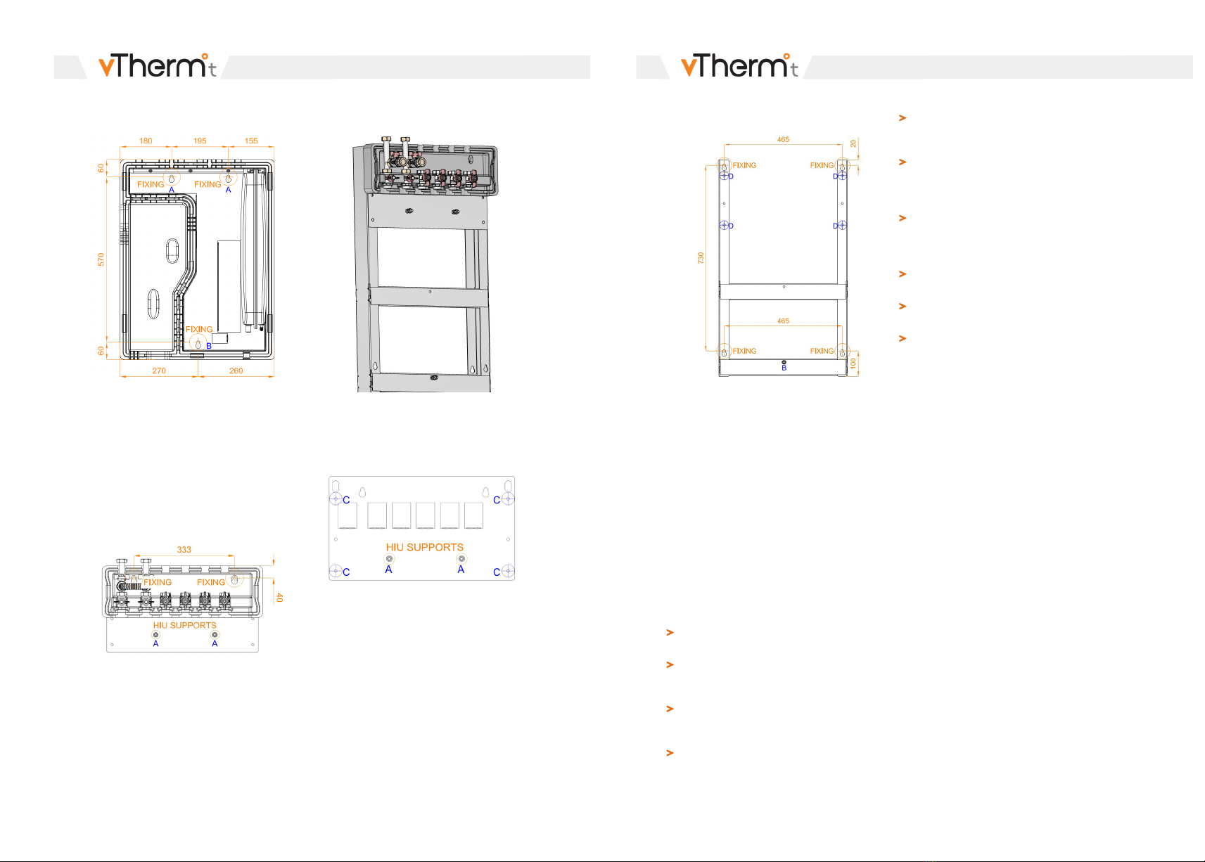
There are three options available for the HIU, which
consider ease of installation, protection of the HIU
and pipework routing up and down (all primary and
secondary connections are on the top of the HIU,
with safety relief connection at the bottom):
1. HIU only option, fixing the HIU directly to the wall.
There are three fixing points on the HIU and all
should be used to secure the HIU. See Fig 4
on the following page, identifying the fixing
positions and dimensions of the HIU:
HEAT INTERFACE UNIT INSTALLATION
Page 14
Fig. 4
HEAT INTERFACE UNIT INSTALLATION
Page 15
2. Valve rail option is installed early during the first
fix with the HIU being installed later. This
approach helps to protect the HIU during the
works. Once the first fix works are complete,
lift the HIU on to the studs (A) on the valve rail
and secure. The lower fixing B (see Fig 4
above) on the HIU will also need to be used for
fixing the HIU. See Fig 5 below, identifying the
fixing positions and dimensions for the valve
rail:
Fig. 5
3. Pipe bracket option: This option should be used
when connections come from below or a
mixture of above and below. See Fig 6 which
identifies the complete assembly, including the
valve rail:
Fig. 6
Step 1. Remove the valves and slide the insulation
off the valve rail to leave the backplate only, see Fig
7:
Fig. 7
Step 2. Construct the pipe bracket frame by
slotting the two horizontal pieces into the two
vertical pieces as shown on opposite page in Fig 8:
Fig. 8
Step 3. Place the backplate onto the frame,
passing the four bolts through C (Fig.7) and then
D (Fig. 8) so the bolt points away from the HIU and
do not foul the valve rail insulation. Tighten all four
nuts and bolts.
Step 4. Fit the frame to the wall.
Step 5. Slide the insulation back onto the valve rail
backplate.
Step 6. Replace all valves.
Step 7. Fit / tighten the nuts and bolts (2 x A and
1 x B), so they are secure in the frame ready for the
HIU installation.
Step 8. When required, lift the HIU on to studs A
and B and use the nuts to secure the HIU.
7.3 Hydraulic Connections
The HIU must be installed by a competent
person(s)
All hydraulic connects are to be made, tested
and filled with the electrical power supply
isolated
Before the HIU is connected hydraulically,
all systems should have been pressure tested,
cleaned and flushed in accordance with BS 7593
Do not flush / back flush through the HIU as this
will result in damage to components
Ensure that pipework connected to the HIU are
self-supported and do not impose stress on the
HIU
Heat from soldering can damage the HIU. Do not
solder final connections or joints close to the HIU
without a break between the appliance and pipe
to prevent heat transfer
All pipework connections must be suitable
for their intended purpose and comply to the
necessary standards. This is the responsibility of
the installer
The isolation valves required for connections A to
F are supplied with the HIU
The connection to the valves supplied with the
HIU for A to F are 3/4” internal thread
The safety relief valve connection G is 1” internal
thread, this connection must be installed in line
with Approved Document G
HEAT INTERFACE UNIT INSTALLATION
Page 16
HEAT INTERFACE UNIT INSTALLATION
Page 17
95.5
53
55
771
65
145
210
275
340
405
A B C D F
G
E
Fig. 9 Top View
Fig. 10 View from Below
Fig. 11 Side View
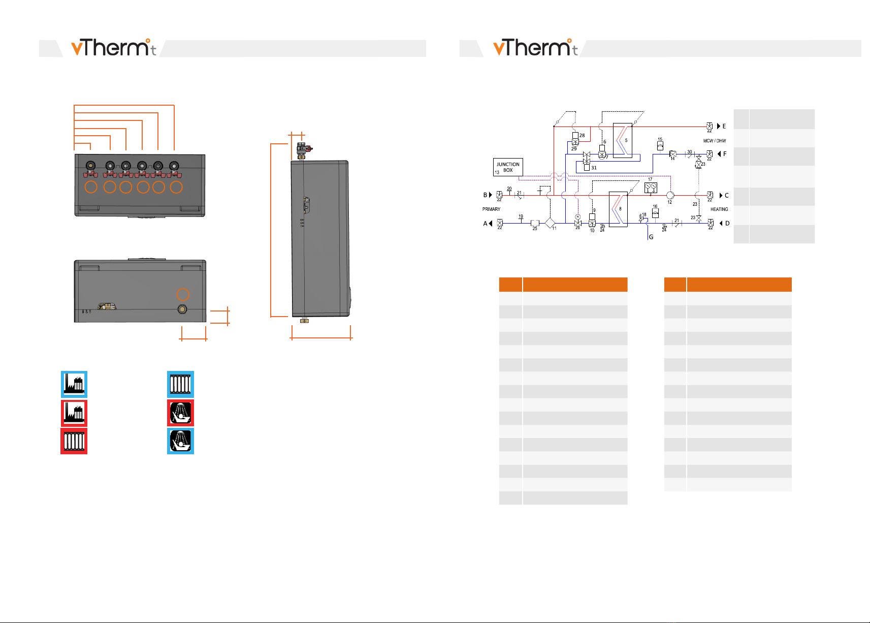
Connections
ADH Primary Return
BDH Primary Flow
CSpace Heating Flow
DSpace Heating
Return
EDomestic Hot Water
FMains Cold Water
GSRV Discharge
REF COMPONENT
1Backplate
2Bracket (Expansion Vessel)
3Bracket (Pipes)
4EPP Cabinet
5DHW Heat Exchanger
6DHW Actuator
7DHW Control Valve
8Heating Heat Exchanger
9Heating Actuator
10 Heating Control Valve
11 Heat Meter (Flow Sensor)
12 Pump
13 Junction Box
14 Check Valve
15 Mini Expansion Vessel
16 Expansion Vessel
REF COMPONENT
17 Thermomanometer
18 Safety Relief Valve (SRV)
19 Test Point (Blue)
20 Test Point (Red)
21 Strainer
22 Ball Valve
23 Filling Loop Connections
24 Drain Valve
25 Spool Piece For Prepay Valve
26 Heating On/Off Valve
27 Heat Meter Calculator
28 Keep Warm Actuator
29 Keep Warm Control Valve
30 MCW Strainer
31 Proportional Flow Controller
Fig. 12 HIU Hydraulic Arrangement
HIU Connections
HIU Components
250
B. Primary Flow
C. Heating Flow
E. Domestic Hot Water
A. Primary Return D. Heating Return
F. Cold Water
G. Heating Safety Valve
Outlet
HEAT INTERFACE UNIT INSTALLATION
Page 18
HEAT INTERFACE UNIT INSTALLATION
Page 19
7.4 Electrical Connections
Electrical connections must be made by an
authorised electrician only.
Electrical connections must be made in
accordance with current regulations and local
standards.
CAUTION
The HIU installation must be undertaken by
qualified/competent mechanical and electrical
engineers. The installation must also be in
accordance with all Building Regulations
applicable to location and the IET Electrical
Regulations.
DANGER
Electricity can cause serious and fatal injuries.
Always isolate the electrical supply and test before
commencing work.
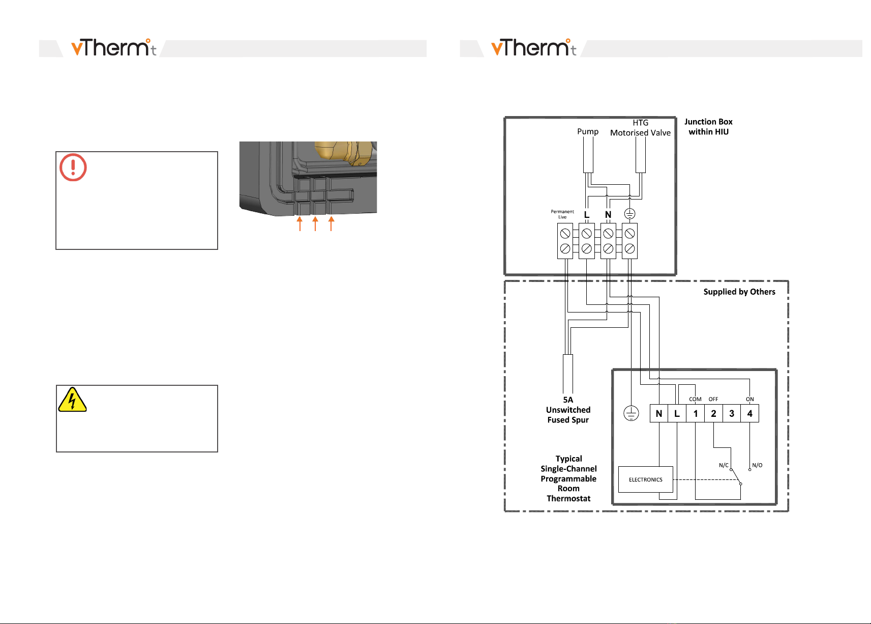
Fig. 13 Guiding Channels
All electrical equipment in the HIU is connected to
the junction box. Before adding power to the unit,
verify that no electrical connections have been
disconnected on the components.
All accessories and main power supply will be
connected in the junction box housing.
Follow the information and wiring diagrams in
Section 7.5.
Check the earth connection; ensure it is sufficient
enough to withstand the power being distributed.
Check the electrical connection reflects the
voltage rating and adheres to current legislation.
Before any electrical work is undertaken, please
refer to safety notes (Section 3).
The HIU should not run via site temporary power
supply. Failure to observe will void the warranty.
HIU must be connected to a 230V un-switched
fused spur fitted with a 5A fuse and wired in
accordance with the BS 7671 Electrical Wiring
Regulations.
Multiple cable guiding channels have been
provided in the insulation casing and must be
used when making the connections to the HIU
(Fig 13).
7.5 Wiring Installation
7.5.1 Wiring Diagram (Radiator)

HEAT INTERFACE UNIT INSTALLATION
Page 20
HEAT INTERFACE UNIT COMMISSIONING
Page 21
7.5.2 Wiring Diagram (Underfloor Heating) 8. COMMISSIONING
Open the kitchen sink DHW tap to allow the
water to flush through the system
Open the DHW isolation valve at the top of the
HIU
Open the MCW isolation valve at the top of the
HIU
8.1 Before Filling the HIU
CAUTION
Flushing and back flushing through the HIU is
strictly prohibited, performing this action will
damage the HIU / Components. Failure to follow
this instruction will invalidate the HIU warranty.
Fig. 14
Refer to Section 3 with regards to tightening of
connections
Obtain pressure test certificates for the MCW,
DHW and HTG systems
Confirm that the Primary side connections
have been completed and are live
Obtain test certificates to show that all
pipework has been flushed / cleaned prior to
connecting the HIU
WARNING
Chemical inhibitors can cause serious injuries.
Always consult manufacturer’s instructions.
Run the water through the kitchen sink tap until
a cold, clean, steady flow of water is achieved
Open each DHW outlet within the property until
all air and any remaining debris has been flushed
through
Check HIU for leaking joints on the secondary
MCW and DHW connections, tighten connections
as required. Do not overtighten the fibre washers
as this will result in damage. Should a fibre
washer become damaged, replace the washer
immediately ensuring to isolate the HIU
mechanically and electrically first
Once all taps have had water drawn off and no
leaks are evident, move to the next step identified
in 8.2.2
Ensure that both drain valves identified in Fig.
14 are closed and end caps are fitted and tight
Confirm that there is an electrical supply to the
HIU which has been isolated
8.2 Filling the HIU with Water
8.2.1 Filling the Secondary MCW and DHW
System
8.2.2 Filling the Secondary Heating System
Open the secondary HTG isolation valves at the
top of the HIU (always open the return valve first
to prevent debris entering the HIU)
Before filling the secondary HTG system introduce
a suitable inhibitor for the type of system
installed, in accordance with the manufacturer’s
instruction and BS 7593
Ensure that both valves identified in Fig 15 are
fully closed
Fig. 15
HEAT INTERFACE UNIT COMMISSIONING
Page 22
HEAT INTERFACE UNIT COMMISSIONING
Page 23
CAUTION
The actuators on the valves must not be
dismantled during operation. This could result in
them being destroyed. Dismantling should only
be carried out when the HIU is isolated from all
systems (mechanical and electrical) and when
the system has cooled down.
Remove end caps and fit flexible hose between
both valves
The secondary HTG circuit pressure should be
typically between 1.0 and 1.5bar, the secondary
HTG system pressure may be read from the
pressure gauge at the front of the HIU
Open the secondary HTG valve first and then
open the MCW valve until the desired pressure
has been achieved
Vent system radiators of all air, top up pressure
after each radiator has been vented
When the system has been fully vented, and
the desired pressure has been achieved, turn
off both valves identified in Fig 15
Remove hose and replace end caps tightly
(always disconnect the filling hose following
use)
Check HIU for leaking joints on the secondary
HTG connections, tighten connections as
required. Do not overtighten the fibre washers
as this will result in damage. Should a fibre
washer become damaged, replace the washer
immediately ensuring to isolate the HIU
mechanically and electrically first
Connect the power cable to the pump (Fig 16).
This cable is removed on purpose to avoid the
pump operating with no water in the system.
To access the pump, move the HIU controller
out of the way
Fig. 16
Once all radiators have been vented, system is at
desired pressure and no leaks are evident, move
to the next step identified in 8.2.3
8.2.3 Filling the Primary System
Only fill the primary system when both
secondary side circuits have been filled as
identified in 8.2.1 and 8.2.2
Open the primary system isolation valves at the
top of the HIU. Always open the flow valve first
to prevent debris entering the HIU
Check HIU for leaking joints on the primary
connections, tighten connections as required.
Do not overtighten the fibre washers as this will
result in damage. Should a fibre washer become
damaged, replace the washer immediately
ensuring to isolate the HIU mechanically and
electrically first
8.3 Finalising the HIU Installation
All joints within the HIU and the final connections
to the HIU are water tight
All DHW outlets have been flushed through to
remove air and debris
All radiators have been vented
Confirm safety relief valve (SRV) has been
connected to drain. Test SRV in line with
manufacturer’s instructions to ensure valve is
operating correctly
WARNING
The safety relief valve is a factory set unit, do
not tamper with the valve. Should the valve not
function when tested or pass water, the valve must
be replaced.
Check all electrical connections are in good
condition and are connected correctly
Confirm all wiring has been completed (power
supply, room stat & programmer) in accordance
with wiring regulations and the HIU has a safe
means of isolating the power supply
8.4 Final Commissioning
Complete correct commissioning form; address,
date, commissioning engineer, HIU details, heat
meter details, confirm any flushing bypass is
closed on the primary connections
Check primary flow temperature is within 5°C of
design set point via the heat meter. If not, wait to
allow hot water to reach HIU
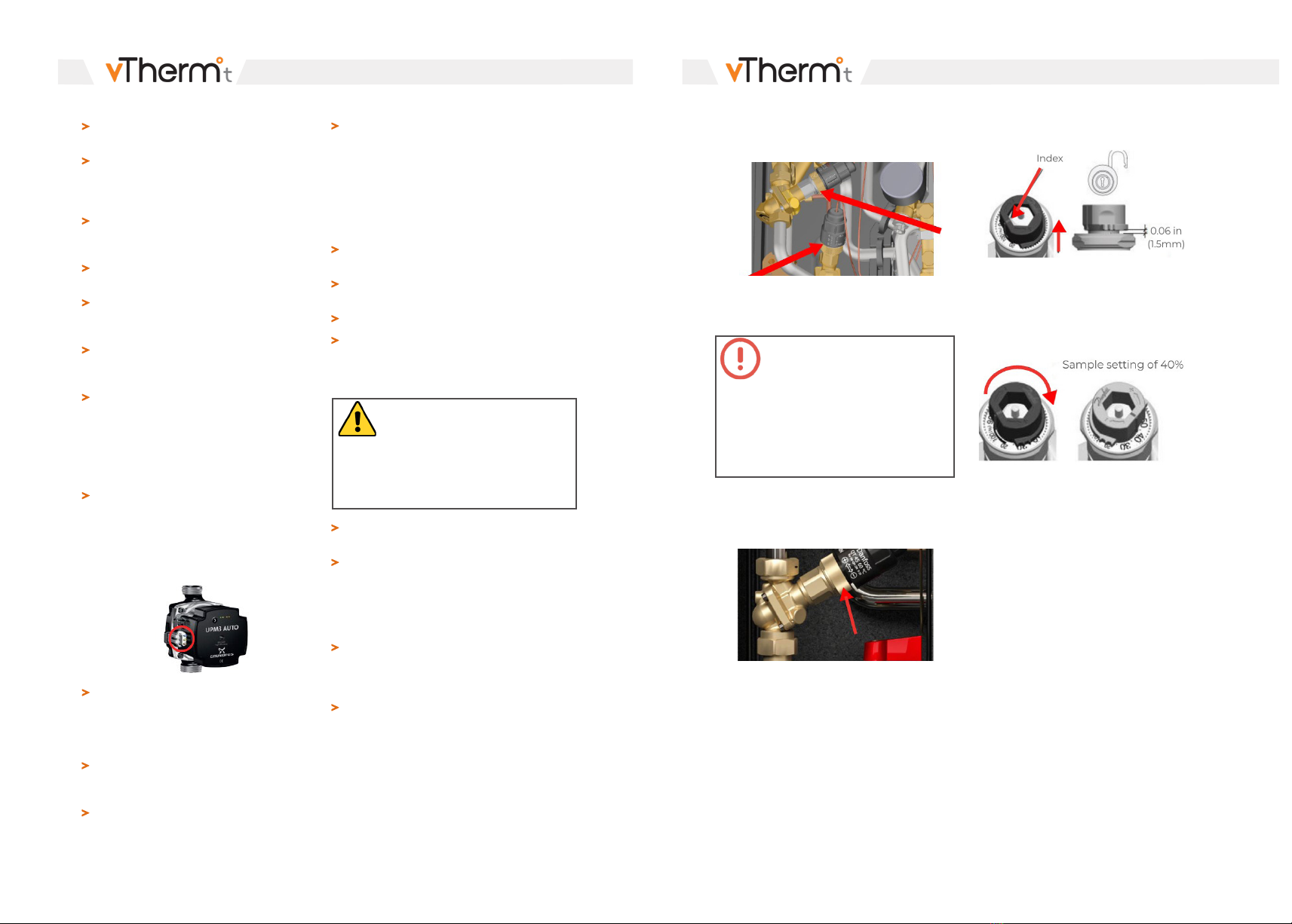
8.4.1 DHW and Keep Warm Control Valve
Adjustment
DHW and keep warm control is provided by Danfoss
AB-QM PICVs. During the commissioning process
the flow rate will need to be checked and adjusted.
See Fig 17 opposite which identifies the location of
(A) DHW PICV and (B) Keep warm PICV.
Fig. 17
Fig. 18
A
B
Before undertaking any of the steps below, close
primary system isolation valves at the top of the
HIU and confirm electrical connection is isolated.
Lift the grey adjustment pointer above the setting
grooves (Fig 19). Located on the adjustment
pointer is a red line which is the index for the
adjustment.
Remove thermostatic actuator by loosening the
brass collar (Fig 18).
Fig. 19
Rotate the pointer to the required flow percentage.
Clockwise to decrease the setting percentage,
counter-clockwise to increase the setting
percentage (Fig 20).
Fig. 20
HEAT INTERFACE UNIT COMMISSIONING
Page 24
HEAT INTERFACE UNIT COMMISSIONING
Page 25
Fig. 21
The pre-setting scale indicates values from 100% flow to 0%, the required volume for the DHW control
valve can be found on the HIU label.
The keep warm setting is dependent upon the primary flow temperature, DHW and keep warm valves
model and setting.
VALVE SETTING FLOW RATE LITRES PER SECOND
VALVE 20% 30% 40% 50% 60%
DN10 LF 0.008 l/s 0.013 l/s 0.017 l/s 0.021 l/s 0.025 l/s
DN15 LF 0.015 l/s 0.023 l/s 0.031 l/s 0.038 l/s 0.046 l/s
DN15 NF 0.025 l/s 0.038 l/s 0.050 l/s 0.063 l/s 0.075 l/s
DN15 HF 0.063 l/s 0.095 l/s 0.126 l/s 0.158 l/s 0.189 l/s
DN20 NF 0.050 l/s 0.075 l/s 0.100 l/s 0.125 l/s 0.150 l/s
DN25 NF 0.094 l/s 0.142 l/s 0.189 l/s 0.236 l/s 0.283 l/s
VALVE 70% 80% 90% 100%
DN10 LF 0.029 l/s 0.033 l/s 0.038 l/s 0.042 l/s
DN15 LF 0.053 l/s 0.061 l/s 0.069 l/s 0.076 l/s
DN15 NF 0.088 l/s 0.100 l/s 0.113 l/s 0.125 l/s
DN15 HF 0.221 l/s 0.252 l/s 0.284 l/s 0.315 l/s
DN20 NF 0.175 l/s 0.200 l/s 0.225 l/s 0.250 l/s
DN25 NF 0.331 l/s 0.378 l/s 0.425 l/s 0.472 l/s
Press grey pointer back into lock position when
flow rate set. After click, pre-setting is locked.
Replace actuator.
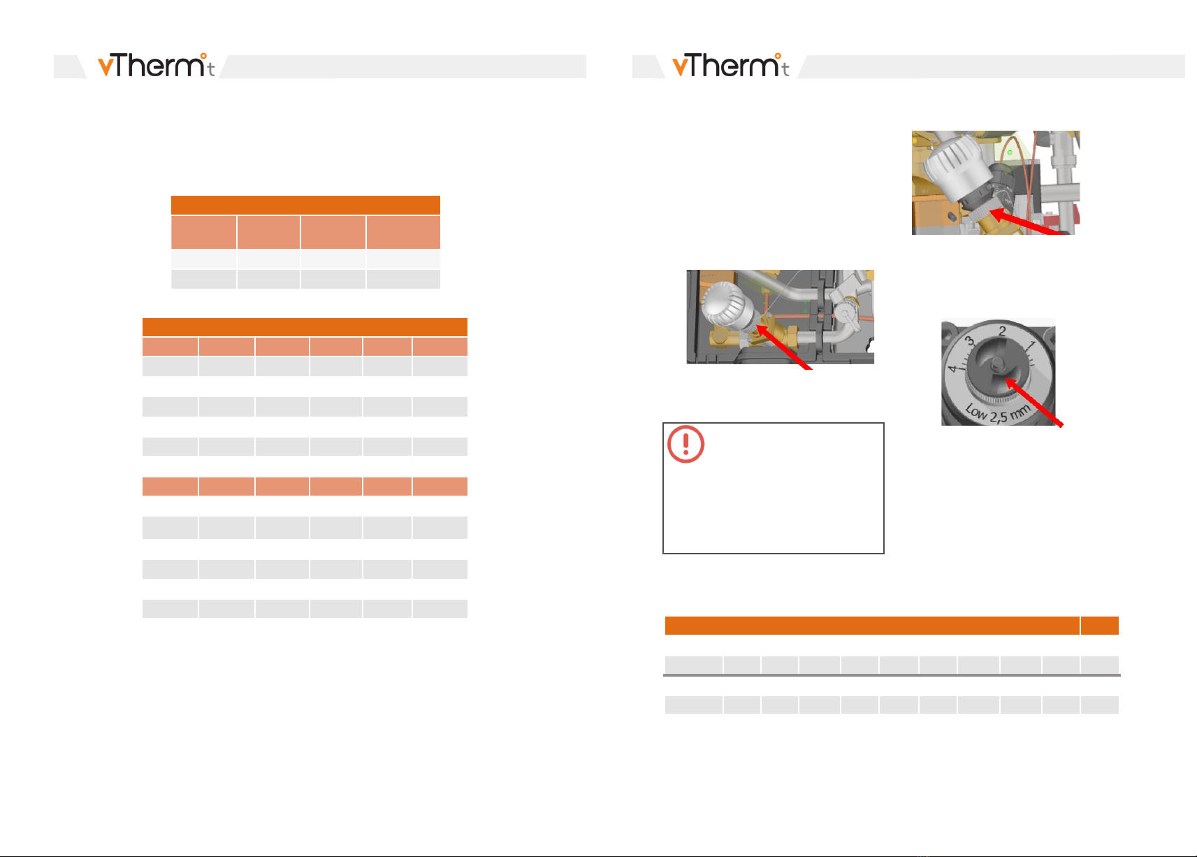
8.4.2 Heating Control Valve Adjustment
Heating control is provided by a Danfoss Frese
Compact PICV. During the commissioning process
the flow rate will need to be checked and adjusted.
See Fig 21 below which identifies the location of
the heating PICV.
Before undertaking any of the steps below, close
primary system isolation valves at the top of the
HIU and confirm electrical connection is isolated.
CAUTION
The actuators on the valves must not be
dismantled during operation. This could result in
them being destroyed. Dismantling should only
be carried out when the HIU is isolated from all
systems (mechanical and electrical) and when
the system has cooled down.
Table 6.
Fig. 23
Remove thermostatic actuator by loosening the
collar (Fig 22).
Fig. 22
Loosen the brass locking nut on the DHW PICV
(See Fig 23) and turn the dial so the pointer aligns
with the correct flow setting. Ensure the locking
nut is re-tightened following adjustment.
The required flow setting for the Frese Low 2.5
valve can be found below in Table 4, if any other
valve is installed refer to the manufacturer's data
sheet. The required volume for the HTG control
valve can be found on the HIU label, i.e. if the
required flow rate is 0.029 l/s set the valve to
setting 2, always align the pointer with the next
number above the required flow rate.
Ensure brass locking nut has been re-tightened.
Refit the DHW control valve actuator and open
primary valves at the top of HIU.
Table 8.
FRESE COMPACT DN10 DN15 2.5 LOW
SETTING 0.5 0.6 0.8 1.0 1.2 1.4 1.6 1.8 2.0 2.2
FLOW (l/s) 0.008 0.010 0.012 0.015 0.018 0.020 0.023 0.026 0.029 0.031
SETTING 2.4 2.6 2.8 3.0 3.2 3.4 3.6 3.8 4.0
FLOW (l/s) 0.034 0.037 0.039 0.042 0.045 0.047 0.050 0.053 0.056
KEEP WARM BYPASS SETUP
PRIMARY
FLOW (°C)
DHW
FLOW (°C)
PICV
SETTING %
ACTUATOR
SETTING NO.
70 55 100 2.5
60 55 100 1
Table 7.

HEAT INTERFACE UNIT COMMISSIONING
Page 26
HEAT INTERFACE UNIT COMMISSIONING
Page 27
8.4.3 Powering up the HIU
Turn on the power to the HIU
DANGER
Electricity can cause serious and fatal injuries.
Always isolate the electrical supply and test
before commencing work.
8.4.4 Heating Set-up
Switch the heating ‘on’ at the thermostat /
programmer and check that the pump is
running, and that the motorised valve opens. If
the pump and the motorised valve do not open,
then check power to the HIU
Press the button on the face of the pump for
more than 2 seconds so that it enters setting
selection mode. The LEDs will flash, showing
the current setting mode. [Note that if the key
lock is disabled, the pump will not switch to
setting selection mode. In this case, unlock the
key lock by pressing the button for more than 10
seconds]
Once in setting selection mode, scroll through
the various options by quick depressions of the
button until the proportional pressure AUTO
ADAPT pattern below is displayed. Release the
button for more than 10 seconds to save the
setting
Check that no water is passing to discharge
through the safety valve
Attach a clip-on temperature sensor onto the
stainless-steel heating flow pipework, as close to
the plate as possible
Adjust the heating actuator until the design
temperature has been achieved and is steady for
three minutes
Complete the ‘Heating’ section of the
Commissioning sheet whilst the HTG is on
Switch the HTG ‘off’ at the room thermostat
and isolate the HIU at the fused spur
Close the secondary HTG isolation valves
WARNING
Risk of burns due to water release under high
pressure and hot surfaces can cause serious burns.
For all operations carried out on the HIU always
wear protective equipment.
COMMISSIONING FORM IMPORTANT NOTE
Before commencement of
commissioning ensure that any
flushing bypass valves are closed
Dwelling Address:
Date:
Commissioning
Engineer:
Heat Interface Unit
Type:
Item:
Cert:
Heat Meter (if installed)
Product name:
Type / size:
Communication
modules:
Serial number:
Initial Reading:
/ (Qp)
(kWh)
Check the secondary side strainer, clean if
necessary and replace
Re-open the secondary heating isolation valves
and re-fill and re-pressurize the system, bleed air
if required
Restore electrical power to the HIU
8.4.5 DHW Set-up
Open either the kitchen sink DHW outlet or
any other outlet without a TMV or thermostatic
control. Using a measuring cap adjust the flow
rate to achieve a constant 12 l/m
Adjust actuator until the DHW temperature of
55° has been achieved at the outlet and is steady
for three minutes
Complete the ‘DHW’ section of the
commissioning sheet whilst the DHW is
running
SECONDARY READINGS PRIMARY HEAT METER READINGS
Flow Temp
(°C)
Return Temp
(°C)
Flow Rate
(m/h)
Flow Temp
(°C)
Return Temp
(°C)
Power
(kW)
HEATING
SECONDARY READINGS PRIMARY HEAT METER READINGS
Location
(Tap DHW
Measured)
DHW Flow
Rate (l/m)
DHW Temp
(°C)
Flow Rate
(m/h)
Flow Temp
(°C)
Return
Temp (°C) Power (kW)
DHW

HEAT INTERFACE UNIT COMMISSIONING
Page 28
HEAT INTERFACE UNIT MAINTENANCE
Page 29
COMMENTS
Commissioning
witnessed by:
On behalf of:
Print name:
Company:
Signature:
Date:
Commissioning
engineer:
9. MAINTENANCE
COMPONENT OPERATION SERVICE FREQUENCY
HIU Check HIU case for damage Every 2 years
Check all HIU fixings are secure Every 2 years
Check all connections for leaks Every 2 years
Check all pipes for mechanical damage and corrosion Every 2 years
Check that the DHW and HTG flow temperatures are correct Every 2 years
Check that the water in secondary systems (take sample)
has been treated in accordance with BS 7593 Code of
Practice for treatment of water in domestic hot water
central HTG systems
Every 2 years
Wiring Check that all electrical wiring is in good condition, tidy and
safe
Every 2 years
Strainers Check and clean all strainers (Primary and Secondary) Every 2 years
Safety Valves Check the safety valve operation Every 2 years
Heating Pressure Check HTG system pressure is between 1.0 and 1.5 bar. Ad-
just pressure if required.
Every 2 years
Heat Meter Check the heat meter for error messages and ensure the
unit is fully functional
Every 2 years
Isolation Valves Exercise all isolation valves, ensuring that they operate
correctly
Every 2 years
Filling Loop Ensure that the space HTG filling valve is in the closed posi-
tion. Flexible hose must be removed after filling
Every 2 years
Bypass If present, check that the flushing bypass valve is closed Every 2 years
Pump Check pump setting is Proportional Pressure Auto Adapt Every 2 years
HTG Control Valve Remove actuator from HTG control valve, check setting of
the valve is correct and matches HIU label, see section 8.4.2
Check that the pin is moving freely before replacing the
actuator
Every 2 years
DHW Control
Valve
Remove actuator from DHW control valve, check setting
of valve is correct and matched HIU label, see section 8.4.1.
Check that the pin is moving freely before the actuator
Every 2 years
ON / OFF Safety
Valve
Remove actuator from keep warm valve, check setting, see
section 8.4.1
Check pin is moving freely before replacing actuator
Every 2 years
Expansion Vessel Test Preloaded Pressure within expansion vessel - 1 bar Every 2 years
Checks When all checks are complete, open valves on HIU and
restore electrical connection:
1. Do not operate heating or DHW, monitor heat meter
return temperature until stable and record temperature
2. Check DHW temperature, see 8.4.5 and record
3. Check HTG temperature, see 8.4.4 and record
Always follow safety instructions with regard to isolation before commencing any work on the HIU.
Isolate mechanically and electronically.
VALVE MAKE SETTINGS (MARK BELOW)
DHW
Temperature (°C)
Danfoss
DHW Flow Setting
(%)
Heating
Temperature (°C)
Danfoss
Heating Flow
Setting (%)
Bypass
Temperature (°C)
Danfoss
Bypass Flow
Setting (%)
20 30 40 60 80
min
1 2 3 4 5 6
0
min
90 10050 70
20 30 40 60 80
min
1 2 3 4 5 6
0
min
90 10050 70
20 30 40 60 80
min
1 2 3 4 5 6
0
min
90 10050 70

HEAT INTERFACE UNIT TROUBLESHOOTING
Page 30
HEAT INTERFACE UNIT TROUBLESHOOTING
Page 31
10. TROUBLESHOOTING
FAULT POSSIBLE CAUSE REMEDY
No Water From DHW
Outlets
1. Mains cold water supply lost / shut off
Check cold water supply to HIU / MCW
outlet / contact local water authority if
necessary
2. Cold water check valve installed in
incorrect direction
Check direction of flow arrows on the valve.
Refit correctly if necessary
3. DHW or MCW isolation valves on HIU
are closed
Open mains cold water and/or domestic hot
water valves on HIU, determine reason for
isolation first to ensure secondary systems
are complete
4. MCW strainer is blocked Remove and clean MCW strainer
Reduced Flow Rate From
Outlets
1. Low mains water pressure Check pressure, consult local water authority
if necessary
2. Plate heat exchanger is partially blocked Remove PHE, clean and re-install or replace
if necessary
3. Size of service pipe to HIU is too small Pipe size should be increased
4. DHW or MCW isolation valves on HIU are
partially closed Open DCW and/or DHW valves on HIU
5. MCW strainer is blocked Remove and clean MCW strainer
1. Check if HIU has power supply
Determine whether HIU is safe, if
determined safe turn power supply on. If HIU
fused outlet is on check local fuse, if fuse is
operating correctly check circuit breakers
No Hot Water
2. HIU primary isolation valves closed Open primary flow and return isolation
valves
3. DHW temperature in actuator is not set
correctly
Check setting of actuator and re-adjust if
necessary
4. DHW PICV / Actuator is not operating or
set correctly
Check setting of PICV, check operation of
actuator and replace if necessary
5. Primary prepayment valve is closed (if
installed)
Check if valve open, check power supply to
actuator, if power present replace actuator
with correct model
6. Local TMV faulty
Check TMV for correct operation, blockages
or setpoint / to confirm TMV issue check
DHW outlet temperature from outlet
without thermostatic mixing
7. No or low flow from primary system Check flow rate on heat meter and consult
network operator if necessary
8. HIU primary strainer is blocked Isolate HIU electrically and mechanically,
allow to cool, remove and clean strainer(s)
9. Low flow temperature from primary
system
Check flow and return temperature on heat
meter to confirm connected correctly, if
connected correctly and flow temperature is
low consult network operator
10. Plate heat exchanger is blocked Remove PHE, clean and re-install or replace
if necessary
FAULT POSSIBLE CAUSE REMEDY
No Heating
1. Check if the HIU has power supply
Determine whether HIU is safe, if
determined safe turn power supply on. If
HIU fused outlet is on check local fuse, if fuse
is operating correctly check circuit breakers
2. Room stat or programmer is incorrectly
set or faulty
Check HTG control operation, replace if
necessary
3. Primary / secondary isolation valves on
HIU are closed Check valves and open if necessary
4. HTG temperature in actuator is not set
correctly
Check setting of actuator and re-adjust if
necessary
5. HTG PICV / Actuator is not operating Check operation of actuator and replace if
necessary
6. Primary HTG On/Off valve is closed
Check if valve open, check power supply to
actuator, if power present replace actuator
with correct model
7. Primary prepayment valve is closed (if
installed)
Check if valve open, check power supply to
actuator, if power present replace actuator
with correct model
8. Low secondary heating system pressure
Connect filling loop and introduce pressure,
vent radiators, remove filling loop when
complete
9. Air lock within HTG system Vent all radiators and top up system
pressure as required
10. HTG circulation pump not working or set
incorrectly
Check HTG pump for correct setting and
operation, replace if necessary
11. High temperature cut-off switch set too
low / is faulty (if installed)
Check setting against design parameters
and operation of cut-off switch / replace if
necessary
12. No or low flow from primary system Check flow rate on heat meter and consult
network operator if necessary
13. Primary or secondary strainers are
blocked
Isolate HIU electrically and mechanically,
allow to cool, remove and clean strainer(s)
14. Low flow temperature from primary
system
Check flow and return temperature on heat
meter to confirm connected correctly, if
connected correctly and flow temperature is
low consult network operator
15. Plate heat exchanger is blocked Check HTG pump for correct operation,
replace if necessary
Water Discharging From
Safety Valve
1. Pressure above 3 bar Shut down HIU, check charge of expansion
vessel and ensure filling loop is closed
2. Faulty Safety Valve Test pressure in space heating if below 3 bar,
replace safety valve if necessary
Pressure Fluctuating
Within Heating System 1. Faulty expansion vessel Check charge (1 bar) within expansion vessel,
re-charge or replace if necessary

HEAT INTERFACE UNIT
Page 32
HEAT INTERFACE UNIT
This brochure is current as from the publication date. This brochure should not be regarded as an infallible
guide and is not an offer for sale of any particular product. Vital Energi Utilities Limited expressly disclaims
any liability in relation to the accuracy or completeness of this information. Any reliance or use of the
information contained within this brochure is at your risk. Vital Energi reserves the right to modify the
technical data and all other information contained within this brochure without notice. All rights reserved.
We strongly recommend you contact Vital Energi to confirm the specifications are to your satisfaction.
[May 2019]
INTENTIONALLY BLANK

viable sustainable energy solutions for the future
For more information about the vTherm˚tHeat Interface Unit (HIU)
www.vitalenergi.co.uk/vTherm
Table of contents
Popular Heater manuals by other brands


Sencor
Sencor SFH 7700WH Translation of the original manual

Forme
Forme HTR-VERTSNGL installation instructions

Toyotomi
Toyotomi Laser 731 Installation and operation instructions

Mathius
Mathius SH6M Installation instructions and user guide

Hyco
Hyco sun king sk1000 instruction manual

USSC
USSC VF30IL user manual


