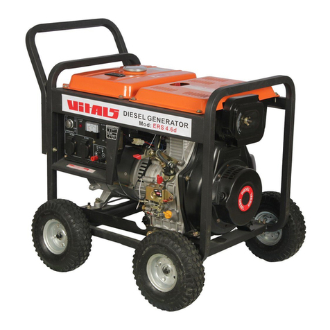
Vitals EST 8.5b User manual

EST 8.5b EST 8.5-3b
AVR
N
+-
WWW.VITALS.COM.UA
P
O
I
W
N
I
E
R
M
S
E
T
N
I
A
L
TI
O
O
S
N
A
S
G

1. 2. 3. 4. 4.1. 4.2. 4.3. 5. 5.1. 5.2. 5.3. 6. 7. 8. 9. 1. 2. 3. 4. 4.1. 4.2. 4.3.5. 5.1. 5.2. 5.3. 6. 7. 8. 9. '1. General description2. Delivery kit3. Technical data4. Safety requirements 4.1.Important safety information 4.2.Operating safety 4.3.Grounding5. Operating 5.1.Proper use 5.2.Before you begin 5.3.Operating mini power station6. Maintenance7. Transportation and storage8. Possible malfunctions andhow to solve them9. Warranty CONTENTS
ENGLISH
589111113151717182128333537394243464648505252535663687072757879828284868787889198103105107

54GENERAL DESCRIPTION1DEAR CUSTOMER! DEAR CUSTOMER! Thank you for buying mini power station Vitals. Vitals techniques are being developed according to European quality standards using modern technologies. Wrong use of the mini power station and inobservance of security measures can lead to damage of the product or to heavy injuries! This manual contains all necessary information on security measures for work with power stations. Carefully read this manual before using the mini power stations. Please provide this manual to other users before they start to work with the mini power stations. This manual is to be conserved for its further use. We are constantly working on the improvement and development of our products and therefore reserve the right to make changes in appearance, accessories and production technology without changing the basic principles of control, without any notification of the user. All possible changes will be directed only to improve and modernize the products.ATTENTION! Means potentially dangerous situations, which can lead to light injuries or damage of the mini power station.NOTE! Marks important additional information.The basis of any mini electrical power stations (hereinafter referred to as power station) is a unit consisting of the internal combustion engine (hereinafter referred to as ICE) and electric generator. The engine and generator are directly connected to each other and strengthened through the shock absorbers on a steel frame.The maximum simplified principle of power plants is as follows: internal combustion engine "transforms" the fuel into the rotation of the shaft, power generator, connected to the shaft of the motor converts the rotations to electrical current.Power plants have the control panel, which helps in managing the power plant, control of its state and protection from accidents.Models EST 8.5b present mobile single-phase power stations alternating-current, models EST 8.5-3b present mobile three-phase power stations alternating-cuurent. The power stations of "Vitals" meet modern technical standards and quality standards, ensuring a long and safe operational period. The difference of the following models is the presence of the electronic module "six in one" (6-in-1) with a numeric display. On the numeric display are shown 6 measures: output AC voltage, output current, connected load, frequency, engine worked hours and output DC voltage.This module allows to read exact measures of output voltage and output current, frequency and connected load. The timer made the engine control method easy.The main components of power stations are presented below.WARNING! Means potentially dangerous situations, which are to be avoided, otherwise can appear a danger for health or life.KEY WORDS MEANING
ENGLISHENGLISH

76figure 21. Air filter body.2. Opening for pouring oil.3. Muffler.4. Spark plug.5. Electric starter.6. Oil dipstick.7. Current generator.1. Frame.2. Fuel tank.3. Fuel tank lid.4. Fuel level indicator.5. Unit for lift.6. Internal combustion engine.7. Ignition lock.8. Choke lever.9. Electronic module 6-in-1.10. Power outlets for 230V.11. Power outlets for 380V.12. AC fuse.13. Grounding terminal.14. DC fuse.15. DC output. 16. AC output power.17. Accumulator battery.figure 1
ENGLISHENGLISH
AVR
N
+-
43125177811161310141512961234675
AVR
N
+-

DELIVERY KIT21. Generator.2. Plug key.3. 3 pin plugs 220V (for model EST 8.5b).4. 2 pin plugs 220V and 1 pin plug 380V (for model EST 8.5-3b).5. Ignition keys.6. Accumulator battery.7. Transportation wheels.8. Manual for use. The manufacturer reserves the right to make design and appearance of the power plants minor changes which do not affect its work.CHNICAL DATACHNICAL DATA3 230 112V - 8,3 24,0 688 + 140/155 8,59,5 145/160 2041,497940640745EST 8.5b EST 8,5-3b230/380500,8MODEL Current frequency, Hz Nominal power, kW Maximal power, kW Power factor (cos ) DC power Voltage regulator Engine type Power, h.p. Cubic capacity, 3 Start system Ignition system Fuel Fuel tank capacity, l Average time of continuous work, h Oil volume in the crankcase, l Acoustic level, dB Low oil level engine sensor Dimens.Dimensions (LWH), mm Weight net/gross, kg AC voltage, V automatic (AVR) four-cycle, twin cylinderselectric start Transistor magnetoGasoline
DimensEngine Current generator
98
ENGLISHENGLISH

1110ATTENTION! During the operation of power station noise level can reach high values! Wear ear protection if necessary.These models have automatic voltage regulator, DC output, electronic module "six in one", time meter and low level of oil in the engine protection system.Automatic voltage regulator (AVR)In power stations there is installed modern automatic voltage regulator, which ensures the stability of the output voltage across the load range. The quality of energy stations, equipped with a voltage regulator, allows them to supply sophisticated electronic equipment, communications, special and residential consumers (computers, televisions, boilers, etc.).DC output Power stations are equipped with a DC output 12V, which is used mainly for charging automobile batteries (12V). Red terminal is positive (+), black - negative (-). Connection must be made according to the polarity.Electronic module "six-in-one" (6-in-1)Electronic module "six-in-one" has a numeric display, where can be shown the values of output AC voltage, output current, connected power, frequency, engine hours worked and output DC voltage. Electronic module allows to show exact values of voltage and current frequency (with one decimal). Also the electronic module allows to count the engine hours worked.TimerThese models are equipped with a timer for engine worked hours. The number of hours worked is displayed on the digital display of the electronic module "six in one". The timer is designed for simple and easy estimation of worked hours every moment. This in turn allows to carry out the maintenance of the engine with accurate intervals. This innovation allows to upgrade the quality of the generator maintenance and, thereby, to increase its operation life several times. Worked hours value can be displayed in hours, minutes and seconds. Engine low oil level protection systemThis alarm system is designed to prevent damage to the engine with insufficient oil in the crankcase. At low levels of oil in the crankcase lamp lights, and turn off the engine protection system that prevents damage.
ENGLISHENGLISH
At an emergency engine stop by the protection system the ignition key of the engine will remain in position «On».SAFETY REQUIREMENTS SAFETY REQUIREMENTS 44.1. IMPORTANT SAFETY INFORMATION4.1. IMPORTANT SAFETY INFORMATION Before using the power station carefully read the safety precautions, warnings and safety instructions in this manual. Most accidents occur when operating stations is a result of non-compliance of basic safety rules and precautions. Accidents can be avoided if the time to be able to foresee the potential danger and subject to safeguards. Situations that result can be a serious bodily injury or damage to the device are marked with the word "WARNING" in this guide. NEVER use a generator means or purposes not foreseen by this manual.PLEASE READ ALL INSTRUCTIONS For safe operation of the unit is necessary to get acquainted with the instructions and appropriate training. Improper use of the unit or operation of an untrained person can be dangerous. Carefully read all parts of the power station. Learn how to turn off the power if necessary. Failure to observe the following instructions can cause electric shock, damage to property, serious damage to health or cause death. HAZARDOUS EMISSIONS OF CARBON MONOXIDE Emissions from power plants contain carbon monoxide - the gas is colorless and odorless. Inhalation of its vapors can cause unconsciousness or death. When you run the power station in a confined space or a room with limited access of air, emission concentration can be dangerous to health. To avoid the accumulation of emissions it is necessary to ensure good ventilation. Do not include a power station in a confined space without sufficient ventilation and hoods.

1312RISK OF ELECTRIC SHOCK When malfunctioning power stations there is a risk of electric shock, or death from electrical shock. Using power stations or other electrical devices in high humidity - near the water, on wet grass during rain or snow - may lead to death from electrical shock. Always keep the power generator dry. The power station is not designed to store unprotected on the street. Moisture or ice can cause a malfunction or an electrical parts, which can lead to death from electrical shock. Check for damaged parts of all electrical power plants to the control panel every time before you start. Before connecting, you must first make the grounding. Failure to follow this may damage property or cause death.INFLAMMABILITY HAZARD Exhaust system heats up during the operation, which can ignite materials being nearby. During and immediately after turning off the power station must be set to 1 meter from foreign objects. Do not cover the station. Keep flammable materials at a safe distance from power station. In the process, power muffler gets very hot and remains hot for some time after it is turned off. Do not touch the muffler while the engine, and while it remains hot. Power necessary to cool before packing and shipment. Gasoline is highly flammable and is very poisonous. Before refueling its power switch off and cool the engine. Do not refill the power station next to an open flame or in a place where there may be a spark. Do not smoke near the power station. Always check for leaks of gasoline. Spilled fuel must be wiped dry before starting the station. Before performing any operation, make sure that the power station is placed on a horizontal surface and rigidly installed.
ENGLISHENGLISH
4.2. OPERATION SAFETY4.2. OPERATION SAFETY1. DO NOT TOUCH THE PARTS IN MOTION.Do not hold hands, fingers and other body parts moving parts power station. Do not touch the fan, it's dangerous.2.DO NOT USE THE POWER STATION FOR NOT INTENDED PURPOSES.Do not use power station for purposes other than those described in this manual.3.KEEP WORK AREA CLEAN.Contamination of the working area can lead to injury.4.DO NOT LET THE CHILDREN AND STRANGERS ENTER THE WORK AREA.5.WEAR APPROPRIATE CLOTHES WHILE OPERATING THE UNIT.Do not wear loose clothing, gloves, neckties, rings, bracelets and other jewelry that can get into the moving parts of the power station. Shoes must not be slippery; you should have a high stability. Gather long hair and wear a cap.6.FOR MAINTENANCE USE ONLY ORIGINAL PARTS.7.DO NOT INITIATE TO WORK AT POWER STATION IN THE STATE OF FATIGUE, ALCOHOL OR AFTER TAKING THE DRUG.8.DO NOT PLACE FLAMMABLE MATERIALS NEAR THE POWER STATION.Near the power station should not be fuel, matches, gunpowder, greasy clothes, straw, trash and other flammable materials.9.DO NOT OPEN THE POWER STATIONS. DO NOT COVER IT. The power station is equipped with forced air cooling system and, if covered, it may overheat.10. THE POWER STATION MUST BE INSTALLED ON A HORIZONTAL SURFACE.No need to create a special stand for the power plant. But it can not be installed on an uneven surface, otherwise it will create vibration. If in the process of work power station is not set stable, it will move, which can pour out fuel and power station itself may tip over, resulting in a precarious situation.If the power station will be installed on a sloping surface, it will not be properly lubricating moving parts, which can lead to jamming cylinder group even if the oil level is normal.

151411. WATCH OVER THE ELECTRIC WIRE SITUATION, LEADING TO THE ELECTRIC POWER CONSUMER. If the power station is standing on the wire or wire is touching its vibrating parts, the wire may be damaged. This can lead to a dangerous situation: the risk of fire, a fire station or electrical shock.12. DO NOT RUN THE POWER STATION WHILE RAINING OR WITH WET HANDS.Working with the power station in rain or snow can cause electrical shock or damage to the power station itself. If the plant gets wet, it must be wiped dry before running. Do not pour water to the power station, do not wash it.13. HANDLE BATTERIES WITH CAUTION.The battery gives off hydrogen gas which can ignite on contact with open flame. The power station must be located in a well ventilated area. Avoid the appearance of flames, sparks when working with battery.14. POWER STATION MAKES HIGH LEVEL OF NOISE.Power station should be located away from work or from the placement of electricity consumers. The optimal distance is 7 m. If you want to work near a power station, wear special ear protection.
ENGLISHENGLISH
Grounding prevents the possibility of electrical shock. To ground you need a ground wire and earthing. They are not supplied with the power station. 2Ground wire must have cross-section of 3.5mm, preferably of twisted copper wire.On Figure 3 is shown ground terminal on the power station. As the earth electrodes can be used the metal pipes of water supply, sewerage located in the ground or metal frames of buildings that have a connection to the ground.ATTENTION! The ground terminal and earthing switch must have a good contact with the ground wire.WARNING! It is strictly forbidden to use power station without grounding!4.3.GROUNDING 4.3.GROUNDINGground terminalfigure 3
AVR
N
+-

1716 If the above mentioned groundings are not available, it is possible to use one of the following earthings: ·a metal rod with a diameter not less than 15 mm and a length of not less than 1500 mm; ·a metal pipe with a diameter not less than 50 mm and a length of not less than 1500 mm; ·a sheet of galvanized steel, uncoated steel size 1000x1500 mmWARNING! For proper earthing connection it should consult a qualified specialist.
ENGLISHENGLISH
OPERATION55.1. PROPER USE5.1. PROPER USE Mini electrical power stations TM Vitals master are a source of energy for electrical appliances. They can provide you with electricity in a variety of circumstances: as a source of emergency power supply for buildings and houses, for repairs without access to the main electrical supply network, in the country house, on a picnic, in the garage, etc. Each model of power station is designed to a maximum capacity of electric power. For proper power selection of the power station, read section 5.3. "Working with the power plant. Model EST 8.5b is single phase and generate electric current with voltage of 230V. You can connect single phase electrical consumers only for this model. Model EST 8.5-3b is three phase and generate electric current with voltage of 230V and 380V. You can connect single phase and three phase electrical consumers for this model. Both models have special developed power outlet to which you can connect maximal acceptable loading (8.5kVA).Also, these models have a DC output voltage.ATTENTION!To single phase power outlet of model EST 8.5b can be connected only single phase electrical consumers with maximal consumer power not more than 6.6kW. ATTENTION! To single phase power outlet of model EST 8.5-3b can be connected only single phase electrical consumers with maximal consumer power not more than 1/3 of electric station power (8,5/3=2,8kVA). If power of connected electrical consumer will be exceeded acceptable power of one phase (one power outlet) there may be phase imbalance arise and power station failed.

1918ATTENTION! It's forbidden to work with a missing air filter or when it is contaminated. This can lead to failure of the engine.7. Check the integrity and purity of the air filter.OilPower stations are supplied without motor engine oil. Pour motor oil into the proper neck (see fig. 4). It is located at the valve cap.figure 4 Figure 6 shows the recommended oil, depending on the ambient temperature. Do not use the power station when there is insufficient or excessive level of motor oil. It should be remembered that the quality of used oil is one of the main factors that affects the normal and continuous work of the engine. Using low-quality oil, you reduce the life of the engine at times.Please use the high quality oil. Do not use special additives to the recommended oil. Do not mix oil with gasoline.
ENGLISHENGLISH
5.2. BEFORE YOU BEGIN5.2. BEFORE YOU BEGIN Before using the power station you need to perform ongoing inspection:1. Carefully inspect the power cable for damage. Pay attention to the integrity of all electrical parts.2. Check hoses, flood openings and the oil tank cover, fuel valve, as well as other possible locations for leaks. If it is needed, fix the leak.3.Check engine oil level and, if necessary, add oil as needed.4.Check fuel level and, if necessary, top up with fuel. In the fuel tank should be kept small air lock for the possible expansion of the fuel vapors when heated.5.Check the mounting of main parts. If necessary, make the tightening of bolts and nuts.6. Check the integrity of the shock absorbers. If necessary, replace them.ATTENTION! Operating the power station with torn or defected shock absorber is prohibited. This can lead to excessive vibration and, consequently, to the failure of the power plant. Check the oil level with dipstick. Figure 5 shows minimal and maximal oil level at the dipstick. figure 5To meet right level of oil you should wait some time after oil filling. This time needed to oil flow down.The recommended rangeLimit of the applicationfigure 6

21FuelUse clean, fresh and unleaded fuels with octane number not lower than 92. Gasoline must be used within 30 days after purchase.Fuel level should be checked before starting the power station. If the engine just stopped, wait for 4-5 minutes or more, so that the engine is cooled down, and only then do the refueling. Refueling should be made so that the tank remained a small air lock for the possible expansion of the fuel vapors when heated.20ATTENTION! Do not use gasoline containing methanol or oil.ATTENTION! Refueling should take place only with the engine off!Air filterDirty air filters can cause hard engine starting, power loss, improper operation of the engine. In addition, dirty air filter can significantly reduce engine life. It is strongly recommended to check the status of the air filter and change it according to the regulations (see Chapter 6 "Maintenance").ATTENTION! It is forbidden to operate without the filter or unfixed filter cover!5.3. OPERATING THE POWER STATION5.3. OPERATING THE POWER STATIONATTENTION! At the beginning of the operation should be performed engine break-in. In detail, see the section below.WARNING! Make sure that the AC and DC power fuses are turned off! It is prohibited to start power station, if there are electricity consumers connected to it and powered! The connected load complicates the run of the power station and may damage it. START
ENGLISHENGLISH
The oil level should be checked in the horizontal position of the generator.

..figure 8 2322If after several attempts the engine has not been started, return the carburetor choke in position RUN and try to repeat above procedure. If there is not enough oil in the engine, it will not start. Check the oil level and, if necessary, add oil.3. Insert the ignition key and turn it into position "START" (Fig. 9) and hold it until the engine starts. After the start release the key. You shouldn't hold the key in "START" position more than 5 sec. If the engine didn't start, refer to "Possible malfunctions and how to solve them. figure 91. Open the fuel valve (see Fig. 7). Turn the fuel cock lever in position ON.figure 7 2. If you start a cold engine (or the temperature is low - lower than +15 º C), turn the choke in position CLOSE (see Fig. 8). In this position of the air damper fuel mixture is enriched, which makes it easier to start. When you run a hot engine (or when the temperature is high enough) enrichment of the fuel mixture is usually not required. If the engine had time to cool down significantly, you may need a partial enrichment, i.e., partial overlap of the choke.
ENGLISHENGLISH
START WITH ELECTRIC STARTER If the engine didn't start, refer to "Possible malfunctions and how to solve them."5. Warm up the engine, letting it run for 1-5 minutes (depending on ambient temperature). You should not warm up the engine at high speeds, it reduces engine life.6. Once the engine is warmed up, it is necessary to remove enrichment of the fuel mixture. To do this, put the choke in position RUN (see Fig. 8). Adjustment of the choke should be done gradually so as not to drown the engine lean fuel mixture.
AVR
N
+-
ON
START
OFF
ONOFF
AVR
N
+-
CLOSEOPENCHOKE
STOPPING1. Turn off the electricity consumers.2. Turn off the fuse on the panel of the power station.3. Turn off the engine by moving the switch to «OFF» (see Fig. 9).4. Close the fuel valve. Turn the fuel cock lever in position «OFF» (Fig. 7).NUMERIC DISPLAYNumeric display shows 6 measures: output AC voltage, output current, connected power, frequency, worked hours number and output DC voltage.V AC voltage currentVA connected powerHz frequencyH worked hours numberV DC voltage
The power station should be set on a flat surface in order to ensure sufficient oil lubrication of the engine.
=

2524
ENGLISHENGLISH
2) Then let the engine work for 1 hour without load. Turn off the engine, let it cool down.3) The first 25 hours the generator should have a load of not more than 50%. The work should be carried out stages, allowing the engine to cool. Each stage of the work should not exceed 3 hours.After 25 hours of use the oil should be changed. It is recommended to make an extra rinse: pour the same motor oil and let engine work for 10 minutes. Drain the flushing oil and pour new oil. The oil for flushing should be selected on the base of the ambient temperature (Fig. 6).
RUNNING-IN One of the most important things is running-in of the new engine. On the correctness of the running time will depend the engine life time. The procedure for running:1) Start the engine and let it warm up. Warmed up engine must work 10 minutes. Turn off the engine and let it cool down. This procedure should be repeated 5 times.
figure 10
By turning on the power station on the numeric display there will be immediately shown the measure of the output AC voltage in V. To display any other measure it is necessary to press the SELECT key. Chose measure will light.
Worked time can be shown in hours, minutes and seconds. From the start will be shown worked time in hours. When pressed again worked time will be shown in minutes and seconds.
When power station is overloaded signal lamp This time there are displayed real measures of voltage, current, connected power and frequency. After power station came back into normal condition you should to push button CLEAR.is start to light.
SELECTCLEAR
VAVAHzHV Electricity consumers can be divided by types of loads. Loads are active and reactive. The active load is the most common load, consumers with such loads of all the energy is converted into heat. Examples: incandescent lamps, irons, heaters, cookers, dryers, etc. To calculate the total power of consumers is sufficient to add the power specified on their labels.·Make sure the devices to be connected are intact and have no defects. Otherwise can occur electric shock or fire.·Ensure that the total electric power of all connected devices does not exceed the rated output power (for continuous operation). Do not connect electric loads capacity exceeding the maximum capacity of the power station.·The work time of the power station in the range between the nominal and maximum power should not exceed 5 minutes. Otherwise, it can cause damage to the power failure.·If you use an extension cord, make sure it is completely unwound, and the cable cross-section corresponds to the connected load. Unequal extension could lead to voltage drops, the cable overheating and instability of connected devices.·Do not overload electrical outlets power. Each outlet has a nominal power, to which it is designed. Try to distribute the load by equal parts between the power outlets. The maximum load on the power outlet is 16A.These single-phase alternating current power station produce AC 230V with frequency 50 Hz. They can only connect single-phase electric loads.It should be noted that many appliances have a so-called starting current which momentarily increase their power consumption by several times. That is, to power the device should be submitted to it the power necessary to run. Starting capacity of such devices should not exceed the maximum capacity of the power station. The appliance with the highest starting power should be connected to the power station as first.LOAD CALCULATION AND CONNECTINGBEFORE CONNECTING ELECTRICAL APPLIANCESMake sure the devices to be connected are intact and have no defects. Otherwise can occur electric shock or fire.Ensure that the total electric power of all connected devices does not exceed the rated output power (for continuous operation). Do not connect electric loads capacity exceeding the maximum capacity of the power station.The work time of the power station in the range between the nominal and maximum power should not exceed 5 minutes. Otherwise, it can cause damage to the power failure.If you use an extension cord, make sure it is completely unwound, and the cable cross-section corresponds to the connected load. Unequal extension could lead to voltage drops, the cable overheating and instability of connected devices.Do not overload electrical outlets power. Each outlet has a nominal power, to which it is designed. Try to distribute the load by equal parts between the power outlets. The maximum load on the power outlet is 16A.LOAD CALCULATION AND CONNECTINGThese single-phase alternating current power station produce AC 230V with frequency 50 Hz. They can only connect single-phase electric loads.It should be noted that many appliances have a so-called starting current which momentarily increase their power consumption by several times. That is, to power the device should be submitted to it the power necessary to run. Starting capacity of such devices should not exceed the maximum capacity of the power station. The appliance with the highest starting power should be connected to the power station as first.
·····
ATTENTION!The starting capacity of the appliances should not exceed the maximum capacity of the power station.

2726 Appliances should be connected to the power station turned on, the fuses and there should be switched off. Turn the fuse, and only then begin to include appliances. The inclusion of multiple appliances should be carried out sequentially and start with a device that consumes the most power. Appliances should be connected to the power station turned on, the fuses and there should be switched off. Turn the fuse, and only then begin to include appliances. The inclusion of multiple appliances should be carried out sequentially and start with a device that consumes the most power.
ENGLISHENGLISH
Reactive loads are consumers with an electric motor, where the energy is consumed in addition on the creating an electromagnetic field. These consumers include pumps, machine tools, power tools, refrigerators, washing machines, etc. A measure of the reactivity parameter is cos . To calculate the actual power consumption of reactive power consumers is need to divide the power by cos . For example: if the drill 600 Watt power value of cos is 0.8, then its work will require power 600W / 0.8 = 750W. This should be considered when calculating the total power of the consumers connected to the generator. The value of cos such devices you can look at the plate, label or instructions of the corresponding device. It is necessary also to keep in mind the following: each power station has its own cos , which must be taken into account. For example, if it is equal to 0.8, for the above drill from the power station will require 750 W: 0.8 = 938 W. In order to avoid overloading the power station the total power of the connected devices should be calculated not more than 80% of rated power of the power station.To summarize, according to the rules of selection power station of the electric current:1.Starting power plug device with the highest starting current should not exceed the maximum output the power station.2.Total power consumption of all devices (with the reactive and active loads) should not exceed the rated output the power station.3.For proper operation of the power station should create power reserve of 20%.4.Connected power customers should not exceed the maximum output the power station outlet (16A).
Model EST 8.5b has the coefficient cos equal to 1. Model EST 8.5-3b has the coefficient cos equal to 0.8.
Maximal acceptable connected loading for single phase of model EST 8.5-3B is 8.5kVA/3*0.8=2.3kW. The engine will automatically increase the speed with increasing load of the generator of electric current. These power stations are equipped with additional power outlet: for model EST 8.5b single phase outlet, for model EST 8.5-3b three phase outlet. (see fig. 11). The engine will automatically increase the speed with increasing load of the generator of electric current. These power stations are equipped with additional power outlet: for model EST 8.5b single phase outlet, for model EST 8.5-3b three phase outlet. (see fig. 11).figure 11
AVR
N
+-

Power stations equipped with modern fuel efficient engines that are designed for long-term and continuous operation. Nevertheless, it is important to hold regular simple maintenance work described in this section. Maintenance is recommended that an experienced specialist. In case of difficulties should request assistance from a professional mechanic.Table Power Station Maintenance ScheduleWARNING! Before you begin to carry out any maintenance work at the power station, turn off the engine and disconnect the ignition wire from the spark.MAINTENANCEMAINTENANCE62928++++++**+*+*+*++*+++++*+*+**MAINTENANCE / RECCOMENDED TERMSFirst 25 work hours or 1 monthEvery 50 work hours or 3 months+*Every work hours or 6 months100 Every300 work hours or 1 yearEvery timeCleaningTighteningCheckingChangeChangeCheckingCleaningChange Gap check,cleaningChangeGap check, CleaningChecking fordamages CheckingCleaningCleaningCheckingChangeEvery 3 year or when neededPower station entireConnections and fasteningsMotor oilOil filterAir filterSpark plugValvesSpark catcherCooling systemIgnition systemPrecipitation tankFuel tank and filterFuel pipe
ENGLISHENGLISH
CLEANINGCleaning of the power station should be carried out after each use and before refilling engine with oil and fuel. It is not allowed to use the power station with oil and fuel stains. It should be remembered that the dust in the engine oil or fuel significantly reduces the engine life. Do not let the dust in generator of electric current, otherwise it may fail.CONNECTIONS AND FASTENINGSPower stations are equipped with internal combustion engines that generate vibration. Vibration is transmitted to the connections and fasteners. Check regularly the tightness of all bolts and nuts and avoid job without any of them. In addition, it is necessary to observe the state of shock absorbers and engine generator. Defective shock absorbers will cause excessive vibration transmission.* - it is recommended more frequent maintenance when used in dusty area generator** - this type of work should be carried out by a qualified technicianATTENTION! Check the rubber damper for wear or damage. Damaged shock absorbers should be changed immediately. These models of power stations are equipped with worked hours timer. You can measure the worked hours every moment the power station is working. You can measure the passed worked hours. This allows to carry out the maintenance works with strict accordance to the schedule. Carrying out the maintenance with strict accordance to the schedule increases the life time several times.To see the worked hours in the numeric display press SELECT, until the LED opposite to H is on. H is for hours. The power station should be set on a flat surface in order to ensure sufficient oil lubrication of the engine.

3130
ENGLISHENGLISH
Motor oil should be drained hot, then drain the oil completely, and takes with it sediments and contaminants of combustion.Filler neck and drain hole are shown in Figure 12.figure 12MOTOR OILATTENTION! Motor oil should be changed after the first 25 hours of work of the new engine.Do not exceed the life of the oil. Change the oil is strictly by the rules.OIL FILTERThese models are equipped with oil filter, which allows for additional cleaning of oil. The oil filter should be changed when changing engine oil.The oil filter is located on the end of the engine.ATTENTION! First, you must drain the used oil, then replace the oil filter and then upload the new motor oil.AIR FILTER A dirty air filter may cause problems when running, power loss, engine malfunction and extremely reduce engine life.SPARK PLUG Regularly clean and check by performance spark plug. Faulty, dirty or having snuff the spark plug is the cause of hard starting and poor engine operation. You must also use a spark plug to the recommended gap of 0.7-0.8 mm (see Fig. 13). figure 13VALVES Cleaning and check valve clearances must be performed by qualified personnel. Please contact the nearest service center for power stations TM Vitals.SPARK CATCHER The muffler has a spark catcher, which prevents the spread of sparks. Over time, spark catcher may get clogged with soot. Clean the spark arrester in accordance with the regulations.COOLING SYSTEM Check the integrity of the impeller engine cooling fan. The absence of even a few wings of impeller may cause overheating of the engine. Partly broken or a broken impeller should be replaced immediately.0,7-0,8 ATTENTION! Do not run the engine with a broken cooling. impeller. A broken impeller can lead to engine overheating and premature motor failure. The air filter should be replaced in proper time. Dirt and dust that penetrates through the air filter, does more harm engine and reduces its service life several times.ATTENTION! It is forbidden to operate without the filter or filter cover with unfixed filter lid!To clean the filter element, use soapy water or nonflammable solvent.

3332
ENGLISHENGLISH
WARNING! The float system, and the needle is not to disassemble and adjust. Wash the bottom of the bath and put it back.FUEL TANK AND FILTER It is recommended to clean the fuel filter and fuel tank every 100 hours or every 6 months (whichever comes first). If it is necessary, reduce the interval. These developments will increase the life of the fuel system. Clean the fuel tank and fuel filter should be made with gasoline.FUEL PIPE Fuel pipe is made of rubber products, which are influenced by environmental and mechanical influences. This does not mean that the fuel pipe is made of bad material. Each material has its own life and property inherent in aging. Fuel pipe is an important element of the engine, it should be emphasized. To prevent possible fuel leaks should be made timely inspection of the fuel line and, if necessary, its timely replacement.IGNITION SYSTEM Correct operation check of the ignition system must be carried out by qualified personnel. Please contact the nearest service center for power stations TM Vitals.PRECIPITATION TANK The precipitation tank is designed to precipitate the possible mechanical impurities in the gasoline. It is located in the carburetor. To clean the tank necessary to unscrew lower front bolt of the carburetor and remove the bottom bath carburetor. Fuel valve must be closed.WARNING! It is possible to get gasoline on the operator's hands. Before cleaning oil and petrol resistance wear oil and petrol resistance gloves. TRANSPORTATION When transporting any the power station should close the fuel valve to prevent fuel leakage. Transporting the power station is allowed only in the horizontal orientation. Otherwise it may leak oil and fuel. You should not carry power over long distances with flooded with fuel and engine oil. This can lead to leakage.Loading and unloading of the power station should be made for a specially designed protective frame. Take care not to damage the power station during the transportation. Do not place heavy objects on it.STORAGE Storage of the power station is recommended dry indoors.In preparing the power station to the storage of fuel must be drained from the fuel tank, fuel pipe and carburetor.WARNING!The power station is very heavy. During the transportation follow the instructions.TRANSPORTATION AND STORAGETRANSPORTATION AND STORAGE7ATTENTION! Do not move the power station with working engine!ATTENTION! Do not touch the engine and exhaust system: they are hot and can cause a fire. Before transporting the power station let it cool down.

3534
ENGLISHENGLISH
In preparation for the long-term storage (more than 2 months):1. Make sure the storage area has not excessive humidity and dust. Power station should be stored in a dry place at the temperature not below 0º C.2. Drain the fuel from the fuel tank, fuel system and carburetor. Remember that gasoline is extremely flammable and under certain conditions, is explosive.3. Change the oil in the crankcase.4. Clean the cabinet the power station from dirt and dust. Apply a thin layer of grease on the site, which is subject to corrosion.5. Set the power station on a flat surface and cover it with a clean, dry material. After the long-term storage of the power station do the following:1. Disconnect the fuel tap and rinse thoroughly.2. Disconnect the carburetor, clean it with petrol and blow jets.3. Replace the fuel cock. Close the fuel valve, fill 1-1.5 liters of gasoline in the tank and shaking the power station in different directions, rinse tank. Drain the gasoline.4. Replace the carburetor.5. Remove the spark plug, wash and clean.6. Check the oil level.ATTENTION! No repair or clean the nozzles with metal objects such as needles and metal wire. POSSIBLE MALFUNCTIONS ANDHOW TO SOLVE THEM POSSIBLE MALFUNCTIONS ANDHOW TO SOLVE THEM 8
Possible cause
Possible solution
Engine is turned off
Turn the ignition key into position "ON"
Fuelis not enough
Refill the fuel
Closed fuel cock
Open it
Clogged spark plug / spark plug out of order
Clean/ change
Not enough oil in the crankcase
Fill up to the level needed
Inappropriate fuel poured
Drain and change to the proper type
Air filter is clogged
Clean or change
Air filter moist
Dry or change
Carburetor clogged
Clean
Fuel pipe clogged
Clean or change
Cold engine
Close the chock
Spark plug is filled with fuel
Clean or change the spark plug
Engine starts under load
Turn off all electricity consumers
Low power of accumulator battery
Recharge or replace the battery
Turn on
Engine does not start The lack of engine power
MALFUNCTION
Engine powershortage
Throttle position don't changeaccording loadBad fuel deliveriNon standart spark plug ChangeCheck / clearfuel systemContact a service centerLow power of accumulator battery Electric starter is out of serviceRecharge or replace the batteryContact a service centerFaulty spark plug Change

3736
ENGLISHENGLISH
MALFUNCTION
Possible cause
Possible solution
Fuse is off
Turn on
Socket is out of order
Contact a service center
Consumer power exceeds the power of the generator
It is not allowed to connect to the consumer more power than the power the power station
Brushes of the generator worked
Contact a service center
Change shock absorbers
Power station operates in spurts (overload)
Reduce the load, turn off consumers of the power exceeding the capacity of the generator
Generator is out of service
Contact a service center
No electricity producedIncorrect operation, machine is out of control
These malfunctions can not describe all possible cases. If your problems are different, contact the nearest service center or a qualified technician. High vibration at the power station (worn shock absorbers)MALFUNCTIONStator or rotor out of order worked outContact a service center
WARRANTY
WARRANTY9
9.
The warranty period for the power stations TM «VITALIS» is 2 (two) year from date of retail sale or 1000 (one thousand) working hours (based on whichever comes earlier). Warranties only apply to defects discovered during the warranty period and the resulting production and design factors. These malfunctions are eliminated at no extra cost by replacing parts or repairs. The warranties can be realized in the special warranty workshops only. The experts of warranty workshop must identify the reasons for the defects. The term of the repair can be more than two weeks because the power station design based on higher engineering attainments. Warranty loses the power in the following cases: No warranty card or the warranty card was destroyed.Do not fully completed warranty card, no sale date or stamp store.The warranty card adulterated.The absence of part or all of the serial number of the product or it differ from the serial number listed in the warranty card.Not complied with the rules of operation are listed in this manual, including the rules of maintenance.Faulty equipment was used and damaged as result. Contact with the inside of the engine and of the generator of foreign matter or object.Use of substandard materials or consumable parts.The presence of the significant mechanical or thermal damage and the consequences of careless using, storage and transporting.Using for other purposes.Unauthorized repair, or attempts to redesign or to disassemble the power station by the user or a third party.Equipment was damaged as result of the natural disaster (fire, water-flood, hurricane etc.).Equipment must be cleared and fully stocked. Faulty parts and assemblies that was replaced must be transmitted to the warehouse of warranty workshop. The warranty does not cover defect due to normal wear and overload.The warranty does not cover consumable parts such as spark plugs, fuel and air filters, pull rope, muffler, amortisseur etc.The warranty does not cover shortage of parts if it can be detected during sale process.All costs associated with transporting the power station is at consumer's side.The warranty is not the ground for another claimes or complaints.

! ! Vitals. Vitals . ! . . , , . . , ' , , , , . .! , .! .! , , '. 1 - ( ) , ( ) . ' . : , , ' , . , , . EST 8.5b , EST 8.5-3b . «Vitals» , . « » (6 1-) . 6 : , , , , , . , , . . .
3938
This manual suits for next models
1
Other Vitals Portable Generator manuals
Popular Portable Generator manuals by other brands
Generac Portable Products
Generac Portable Products 4000EXL owner's manual
Champion
Champion 71000i Owner's Manual and Operating Instructions
Power Stroke
Power Stroke PS905700D Quick reference guide
MQ Power
MQ Power WHISPERWATT Series Operation manual
WhisperPower
WhisperPower W-SQ 27 kVA / 25 kW installation manual
B+K precision
B+K precision 4013DDS instruction manual
WhisperPower
WhisperPower M-SC6 installation manual
WhisperPower
WhisperPower W-SQ-Pro user manual
OutBack Power
OutBack Power Alino TL Series owner's manual

Power House
Power House PH6500Ri quick start guide

MQ Power
MQ Power WHISPERWATT DCA180SSJU4F Operation manual
Power House
Power House PH3100RI Shop Manual
