Vivace HART VTT10-FH Quick guide

INSTALLATION, OPERATION, CONFIGURATION AND MAINTENANCE MANUAL
July/2019
VTT10-FH
HART® TEMPERATURE TRANSMITTER
field model

VTT10-FH HART
®
TEMPERATURE TRANSMITTER INSTALLATION, OPERATION, ONFIGURATION AND MAINTENAN E MANUAL
______________________________________________________________________________________________________________________________
2
COPYRIGHT
All rights reserved, including translations, reprints, complete or partial reproduction of this
manual, patent concession or model register of use/project.
No part of this publication may be reproduced, copied, processed or transmitted on any manner
or any medium (photocopy, scanning, etc.) without the express permission of Vivace Process
Instruments Inc., not even for training or electronic systems.
HART
®
is a registered mark of HART Communication Foundation.
NOTE
We have reviewed this manual with great care to maintain compliance with the hardware and
software versions described herein. However, due to the dynamic development and version upgrades,
the possibility of technical deviations cannot be ruled out. We cannot accept any responsibility for the
full compliance of this material.
Vivace reserves the right to, without notice, make modifications and improvements of any kind
in its products without incurring in any circumstances, the obligation to make those same modifications
to products sold previously.
The information in this manual is frequently updated. Therefore, when using a new product,
please check the latest version of the manual on the Internet through our website
www.vivaceinstruments.com, where it can be downloaded.
You customer is very important for us. We will always be grateful for any suggestions for
improvements as well as new ideas, which can be sent to the e-mail: contato@vivaceinstruments.com
preferably with the title "Suggestions".

VTT10-FH HART
®
TEMPERATURE TRANSMITTER INSTALLATION, OPERATION, ONFIGURATION AND MAINTENAN E MANUAL
______________________________________________________________________________________________________________________________
3
SUMMARY
1
EQUIPMENT DESCRIPTION ........................................................................................................ 6
1.1.
BLO K DIAGRAM ......................................................................................................................................... 6
2
INSTALLATION ............................................................................................................................ 8
2.1.
ME HANI AL ASSEMBLY ........................................................................................................................... 9
2.2.
ELE TRI AL ONNE TION ...................................................................................................................... 11
2.3.
PRO ESS ONNE TION ........................................................................................................................... 13
3
CONFIGURATION ...................................................................................................................... 14
3.1.
LO AL ONFIGURATION .......................................................................................................................... 14
3.2.
JUMPER ONFIGURATION FOR LO AL ADJUST AND WRITE PROTE TION ...................................... 15
3.3.
LIQUID RYSTAL DISPLAY (L D) ............................................................................................................. 16
3.4.
LO AL ADJUST ONFIGURATION TREE ................................................................................................. 16
3.5.
HART
®
ONFIGURATOR ............................................................................................................................ 17
3.6.
HART ONFIGURATOR PROGRAMMING TREE ...................................................................................... 18
3.7.
FDT/DTM ONFIGURATION....................................................................................................................... 20
4
MAINTENANCE ..........................................................................................................................
4.1.
HART PROGRAMMER DIAGNOSTI S ...................................................................................................... 22
4.2.
ADDITIONAL DIAGNOSTI S ...................................................................................................................... 22
4.3.
ASSEMBLY AND DISASSEMBLY PRO EDURE ....................................................................................... 23
4.4.
SPARE PARTS ............................................................................................................................................ 24
5
CERTIFICATION ......................................................................................................................... 5
6
TECHNICAL CHARACTERISTICS ............................................................................................. 6
6.1.
IDENTIFI ATION ......................................................................................................................................... 26
6.2.
TE HNI AL SPE IFI ATION..................................................................................................................... 26
6.3.
OMPATIBLE SENSORS ............................................................................................................................ 27
6.4.
ORDERING ODE....................................................................................................................................... 28
7
WARRANTY ............................................................................................................................... 9
7.1.
GENERAL ONDITIONS ............................................................................................................................. 29
7.2.
WARRANTY PERIOD .................................................................................................................................. 29
APPENDIX ........................................................................................................................................ 30

VTT10-FH HART
®
TEMPERATURE TRANSMITTER INSTALLATION, OPERATION, ONFIGURATION AND MAINTENAN E MANUAL
______________________________________________________________________________________________________________________________
4
1
It is extremely important that all the safety instructions, installation and operation in this manual are
followed faithfully. The manufacturer is not liable for damage or malfunction caused by improper use
of this equipment.
It is recommended to strictly following the rules and good practice relating to installation, ensuring
correct grounding, noise insulation and good quality cables and connections in order to provide the
best performance and durability to the equipment.
Special attention must be considered in relation to installations in hazardous areas, where applicable.
WARNING
•Appoint only skilled people, trained with process and equipment;
•Install equipment only in operation compatible areas, with the proper connections and
protections;
•Use proper safety equipment for any handling device in field;
•Turn area power off before equipment installation.
SAFETY PROCEDURES
SYMBOLOGY
Caution - indicates risk or error source
Important Information
General or Specific Risk
Electric Shock Danger

VTT10-FH HART
®
TEMPERATURE TRANSMITTER INSTALLATION, OPERATION, ONFIGURATION AND MAINTENAN E MANUAL
______________________________________________________________________________________________________________________________
5
GENERAL INFORMATION
Vivace Process Instruments ensures the operation of this equipment, according to the
descriptions contained in its manual, as well as technical characteristics, not
guaranteeing its full performance in particular applications.
The operator of this equipment is responsible for observing all aspects of safety and
prevention of accidents applicable during the execution of the tasks in this manual.
Failures that might occur in the system, causing damage to property or injury to
persons, shall additionally be prevented by external means to a safe outlet for the
system.
This equipment must be used only for the purposes and methods proposed in this
manual.

VTT10-FH HART
®
TEMPERATURE TRANSMITTER INSTALLATION, OPERATION, ONFIGURATION AND MAINTENAN E MANUAL
______________________________________________________________________________________________________________________________
6
1 EQUIPMENT DESCRIPTION
VTT10-FH is the field model for Vivace’s temperature transmitter family, projected to be installed
directly on sensor or on a Ø 2” tube, panel or wall. It attends several sensor types, such as thermocouple,
RTDs, resistance and millivoltage signals.
The transmitter is powered by a 12 to 45 Vdc voltage and modulates communication over a 4-20 mA
output signal, according to NAMUR NE43 standard, using HART
®
protocol. The configuration uses HART®
7 (older versions compatible) communication protocol, already established on the world of industrial
automation for configuration, calibration, monitoring and diagnostics.
Through a HART configurator or any EDDL or FDT/DTM-based tool it is possible to configure sensor
type, measuring range, work unit, calibration and also monitoring measured variables with device status.
Configuration via local adjust is also possible with an auxiliary magnetic screwdriver.
Focusing on high performance and robustness, it was projected with the most recent electronic
component and material technology, offering long-term reliability for every scale systems.
1.1. BLOCK DIAGRAM
Component modularization for transmitter is described on the following block diagram.
Figure 1.1 – Transmitter block diagram.
The sensor signal passes through RF EMI filter and goes to ADC block, where it is converted to a
digital value. This digital value later will be converted in the temperature, according to selected sensor type.
The temperature value is finally converted in a current signal, proportional to the calibrated range.
The sensor signal is galvanic isolated from output signal, avoiding ground loop.

VTT10-FH HART
®
TEMPERATURE TRANSMITTER INSTALLATION, OPERATION, ONFIGURATION AND MAINTENAN E MANUAL
______________________________________________________________________________________________________________________________
7
The input block (DC power supply) is responsible for the electric source for all circuits. Current control
block is composed by a circuit to transform digital values generated by microcontroller into 4-20 mA electric
current, proportional to the primary variable value.
HART
®
channel and HART
®
modem blocks provide the interface between microcontroller signals
and HART
®
bus connected to monitored device. Local adjust block enables local configurations by user.
The display board has the controller block to interface LCD and CPU communication signals,
adapting all the messages to be shown on display.
Finally, the CPU block can be seen as the transmitter brain, where all the activities happen, such as
time control, HART
®
machine, besides the common transmitter routines: configuration, calibration and
generation of output current, proportional to the primary variable.

VTT10-FH HART
®
TEMPERATURE TRANSMITTER INSTALLATION, OPERATION, ONFIGURATION AND MAINTENAN E MANUAL
______________________________________________________________________________________________________________________________
8
2 INSTALLATION
RECOMMENDATION
When taking the equipment to the installation location, transfer it in the original packaging.
Unpack the equipment at the installation location to avoid damage during transportation.
RECOMMENDATION
Model and specification of equipment are indicated on identification plate, located at the top of
the housing. Check if supplied specification and model correspond to application requirements.
STORAGE
The following precautions should be observed when storing the equipment, especially for a
long period:
1) Select a storage area that meets the following conditions:
a) No direct exposition to rain, water, snow or sunlight.
b) No exposition to vibration and shocks.
c)
Normal temperature and humidity (around 20°C / 70°F, 65% RH)
.
However, it can also be stored under the following temperature and humidity intervals:
●Ambient Temperature: -40°C to 85°C (without LCD)* or -30°C to 80°C (with LCD)
●Relative Humidity: 5% to 98% RH (@ 40°C)
(2) For equipment storage, use original factory package (or similar).
(3) If storing an already used Vivace equipment, dry every moist part and clean all
connections that was in contact with the process. Keep covers and connections closed and
properly protected for its specific application and requirements.
* Only for general use. For explosion proof version, follow product certification requirements.

VTT10-FH HART
®
TEMPERATURE TRANSMITTER INSTALLATION, OPERATION, ONFIGURATION AND MAINTENAN E MANUAL
______________________________________________________________________________________________________________________________
9
.1. MECHANICAL ASSEMBLY
VTT10-FH was developed to be installed in the field, thus supporting exposition to several
environment situations, keeping good performance through any temperature, humidity and vibration
variations.
The transmitter’s housing is IP67 protected, being immune to water contact to electronic circuit and
electrical connections, since cable gland or conduit for electrical connection is correctly assembled and
sealed with non-hardening substance. Covers must also be tight to avoid humidity, since housing screws
are not protected by painting.
The electronic circuit is protected by varnish but constant water or corrosion exposure may
compromise this protection and damage the electronic components.
Figure 2.1 shows the dimensional drawing and mounting positions for VTT10-FH.
Figure 2.1 – Dimensional and mounting drawings for VTT10-FH.
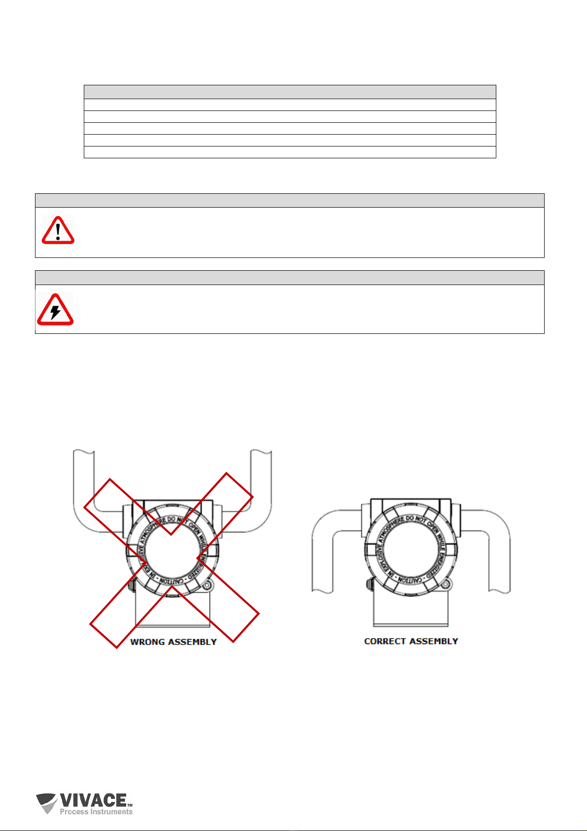
To avoid the risk of involuntary loss of VTT10-FH covers due to vibration, for instance, it can be
locked by screw, as shown on figure 2.2.
VTT10-FH is a field device, so it can be installed through a mounting bracket on a 2” tube attached
with a U clip. For best LCD positioning device enables its display to be rotated 4 x 90°, according to figure
2.3. The transmitter can also be attached with the same mounting bracket to a wall or panel.

VTT10-FH HART
®
TEMPERATURE TRANSMITTER INSTALLATION, OPERATION, ONFIGURATION AND MAINTENAN E MANUAL
______________________________________________________________________________________________________________________________
10
Figure 2.2 – Front cover lock.
Figure 2.3 – Housing positioning.
VTT10-FH liquid crystal display can be rotate 4 x 90° so indication will be adequate for user
visualization.
Figure 2.4 illustrates rotation possibilities for VTT10-FH LCD.
Figure 2.4 – 4 x 90° LCD rotation.

VTT10-FH HART
®
TEMPERATURE TRANSMITTER INSTALLATION, OPERATION, ONFIGURATION AND MAINTENAN E MANUAL
______________________________________________________________________________________________________________________________
11
. . ELECTRICAL CONNECTION
In order to access the terminal block user must remove VTT10-FH rear cover. First, loose cover lock
screw (see figure 2.5) by turning it clockwise.
Figure 2.5 – Rear cover lock.
Figure 2.6 shows the terminals for power supply (PWR BUS) and the sensor terminals (1, 2, 3, 4). It
also shows the grounding terminals (internal and external) and HART communication terminals for VTT10-
FH. For powering the device, it is recommended to use a 22 AWG twisted pair cable.
Figure 2.6 – Terminal connection and description.
VTT10-FH HART
®
TEMPERATURE TRANSMITTER INSTALLATION, OPERATION, ONFIGURATION AND MAINTENAN E MANUAL
______________________________________________________________________________________________________________________________
12
Table 2.1 describes VTT10-FH terminal functions.
Table 2.1 – Terminal description.
NOTE
All cables used for connecting VTT10-FH with HART
®
network must be shielded to avoid
interference or noise.
Conduits used for power cables must be assembled in order to avoid water entrance in the device
terminal block. Conduit screws must be sealed according to specific area required standards.
Non-used electrical connection must be sealed with appropriate cover.
Figure 2.7 shows the correct installation for conduit, in order to avoid the entrance of water or any
corrosive material that may cause damage to the device.
Figure 2.7 – Conduit installation.
Termina
l Description
Power Terminals – PWR BUS - 24 Vdc not polarized
Grounding Terminals – 1 internal and 1 external
Test Terminals – TEST – current loop measurement (4-20 mA) without open circuit
Communication Terminals – COMM – HART
®
communication with configurator
Sensor Terminals – temperature sensor connection terminals
NOTE
It is extremely important to ground the equipment for complete eletromagnetic protection and
also to ensure the correct performance of transmitter on the HART network.

VTT10-FH HART
®
TEMPERATURE TRANSMITTER INSTALLATION, OPERATION, ONFIGURATION AND MAINTENAN E MANUAL
______________________________________________________________________________________________________________________________
13
.3. PROCESS CONNECTION
Following are illustrated the VTT10-FH sensor connection for different sensor types:
Figure 2.8 – 2-wire RTD or resistive sensor connection. Figure 2.9 -3-wire RTD or resistive sensor connection.
Figure 2.10 - 4-wire RTD or resistive sensor connection. Figure 2.11 – Differential, maximum, minimum or backup
RTD or resistive sensor connection.
Figure 2.12 – Thermocouple or mV sensor connection. Figure 2.13 - Differential, maximum, minimum or backup
thermocouple or mV sensor connection.
Figure 2.14 – 4–20 mA input connection

VTT10-FH HART
®
TEMPERATURE TRANSMITTER INSTALLATION, OPERATION, ONFIGURATION AND MAINTENAN E MANUAL
______________________________________________________________________________________________________________________________
14
3 CONFIGURATION
The transmitter can be configured by any HART
®
compatible programmer. Vivace offers the
interfaces VCI10-H (USB, Android and Bluetooth) as a solution for configuring and monitoring any HART
®
device. VTT10-FH can also be configured by local adjust using Vivace magnetic screwdriver.
3.1. LOCAL CONFIGURATION
Transmitter’s local configuration is executed by using Vivace’s magnetic
screwdriver on Z and S orifices, located at housing superior side, under
identification plate. Orifice Z starts local configuration and changes the field to
be configured. Orifice S is responsible for changing and saving the new value
on the selected field. Saving after LCD value changing is automatic.
Figure 3.1 shows orifices Z and S for local configuration, stamped on device
housing, and their functions on magnetic screwdriver actuation.
Insert the magnetic screwdriver on Zero orifice (Z). icon appears to indicate
that device has recognized the screwdriver action. Keep the magnetic
screwdriver inside until “LOCAL ADJST” message is shown on display, then
remove it for 3 seconds. Insert the magnetic screwdriver into Z orifice again, so
user can navigate through local adjust parameters.
Table 3.1 indicates actions executed by magnetic screwdriver when inserted
on Z and S orifices.
Table 3.1 – Z and S orifices actions.
Figure 3.1 – Z and S orifices and
magnetic screwdriver.
Some parameters show the icon to allow user configuration on it by inserting the magnetic
screwdriver into Span orifice (S). In case the parameter has pre-defined values, those will be rotate on
display, while the magnetic screwdriver remains into Span orifice (S).
If the parameter is numerical, this field will enter on edition mode and decimal point will start blinking,
and shifting to left. When user removes magnetic screwdriver from S, the least significant digit (in the right)
starts blinking, indicating it is ready for edition. By inserting the magnetic screwdriver into S, user is enabled
to increase the digit value, from 0 to 9.
After the least significant digit edition, user should remove magnetic screwdriver from S in order to
start the edition of the next digit (in the left). User will be able to edit each digit independently, until the most
significant digit (5th digit on the left) is complete. After the 5th digit edition, user can also change the signal
for the numerical value still on S orifice.
During each step of edition, user is able to return to the previous digit (to the right) by inserting the
magnetic screwdriver into Z orifice, so corrections can be made. By removing the magnetic screwdriver at
any time, user will see the digits blinking until the final step, where the edition mode will be finished, saving
the numerical value configured by user.

VTT10-FH HART
®
TEMPERATURE TRANSMITTER INSTALLATION, OPERATION, ONFIGURATION AND MAINTENAN E MANUAL
______________________________________________________________________________________________________________________________
15
If the configured value is not acceptable by that device parameter (invalid value), it will be returned
to the last valid value before edition. Depending on the parameter, some values can be shown on numerical
or alphanumerical fields, adjusting the best option view to user.
With the magnetic screwdriver out of Z and S orifices, device will leave local adjust mode after some
seconds and monitoring mode will be shown.
3.2.JUMPER CONFIGURATION FOR LOCAL ADJUST AND WRITE PROTECTION
VTT10-FH has two jumpers on its main board to protect data writing (WP1) and also
enabling/disabling local adjust (ADJL1). Figure 3.2 presents those jumpers.
Figure 3.2 – Jumpers WP1 (write protection) and ADJL1 (local adjust) on VTT10-FH main board.
Default selection for these jumpers is Write Protection DISABLED and Local Adjust ENABLED.

VTT10-FH HART
®
TEMPERATURE TRANSMITTER INSTALLATION, OPERATION, ONFIGURATION AND MAINTENAN E MANUAL
______________________________________________________________________________________________________________________________
16
3.3.LIQUID CRYSTAL DISPLAY (LCD)
Main information related to transmitter are indicated on its liquid crystal display (LCD). Figure 3.3
shows the LCD with all its indication fields. Numerical field has 5 digits and is used mainly for monitored
variable indication. Alphanumerical field indicates which variable is being monitored, units or auxiliary
messages. Each indication icon use is described on table 3.2.
Figure 3.3 – LCD fields and icons. Table 3.2 – LCD icon description.
3.4.LOCAL ADJUST CONFIGURATION TREE
Figure 3.4 shows available fields for local configuration and the sequence they are presented by
magnetic screwdriver actuation on Z and S orifices.
Figure 3.4 – Local adjust configuration tree.

VTT10-FH HART
®
TEMPERATURE TRANSMITTER INSTALLATION, OPERATION, ONFIGURATION AND MAINTENAN E MANUAL
______________________________________________________________________________________________________________________________
17
3.5. HART
®
CONFIGURATOR
Figure 3.5 exemplifies the use of USB interface with a personal computer that has a HART
®
configurator installed. A 250Ωresistance must be serially connected with the power supply (for voltage
supply and if the power supply does not have this resistance internally) in order to enable HART
®
communication over the 4-20 mA current (Figure 3.5). Vivace interface already has this resistance when
used to power the field device (Figure 3.6).
Figure 3.5 – Transmitter installation for configuration with external power supply and 250 ohms resistance.
Figure 3.6 – Transmitter installation for configuration using VCI10-UH to power the device.
VTT10-FH multidrop connection must be executed according to Figure 3.7. Note that up to 63 devices
can be paralleled connected on the same line. Caution must be taken when many transmitters are
connected on the same power line due to voltage drop on 250 ohm resistor and guarantee power supply
voltage is enough (Figure 3.8).
Figure 3.7 – Multidrop connection for VTT10-FH.

VTT10-FH HART
®
TEMPERATURE TRANSMITTER INSTALLATION, OPERATION, ONFIGURATION AND MAINTENAN E MANUAL
______________________________________________________________________________________________________________________________
18
Figure 3.8 – VTT10-FH load curve.
3.6. HART CONFIGURATOR PROGRAMMING TREE
The configuration tree is a structure tree-shaped with the menus for all software resources available,
as shown on figure 3.9.
For online configuration of the transmitter, check it is correctly installed, powered by the adequate
voltage and with the minimum load of 250 Ωimpedance on the line, necessary for communication.
Figure 3.9 – VTT10-FH programming tree.

VTT10-FH HART
®
TEMPERATURE TRANSMITTER INSTALLATION, OPERATION, ONFIGURATION AND MAINTENAN E MANUAL
______________________________________________________________________________________________________________________________
19
Information – Main device information can be accessed here.
•HART
®
– Main information about communication protocol are available here, such as:
Manufacturer, Device Type, Device Profile, HART
®
Revision, Software Version etc.
•Sensor – Main information about the sensor are available here, such as: Sensor
Type, Connection (2, 3 or 4 wires), Upper Range, Lower Range and Unit.
Configuration – Configuration of transmitter Work Ranges, Unit, Safe Mode and Damping are available
here.
•Damping is an electronic filter for PV variable which changes transmitter response time in
order to smooth output reading variations caused by input fast variations. Damping value can be configured
between 0 and 60 seconds, and its appropriated value must be adjusted based on process response time,
output signal stability and other system requirements. Default value for damping is 0 seconds.
The damping value affects transmitter response time. When this time is configured as zero, the
damping function is disabled and transmitter output will react immediately to the input variations, so the
response time will be as short as possible.
An increase to the damping value will result on an increase to transmitter response time.
As the settling time constant is defined, transmitter output will achieve 63% of the input variation and
transmitter will continue to approach the input value according to damping curve.
•Sensor – Sensor Type, Sensor Connection and Cold Junction Mode.
•Callendar van Dusen – R0, A, B and C parameters of Callendar van Dusen for RTDs.
Callendar-Van Dusen is an equation which describes the relation between the resistance
(R) and the temperature (t) of RTD platinum resistance thermo-elements.
•Table – Table function with its parameters.
•Display – Configure two variables to be displayed on LCD.
Trim – Enables the adjustment for transmitter output current, input temperature sensor (ohm or mV) and
internal temperature sensor. Figure 3.10 shows the connection for current TRIM on VTT10-FH.
Maintenance – This menu enables transmitter reset, change counter verification/reset, write protection,
data backup/restore and loop test function (fixed current mode).
•Alteration Counter – checks the number of changes executed in several parameters
with the possibility of resetting them.
•Max/Min Values – Shows maximum and minimum values for PV and SV.
Observe – Monitoring view for output current, PV%, PV, SV, TV and QV.
Diagnosis – Monitoring view for device alarm status.

VTT10-FH HART
®
TEMPERATURE TRANSMITTER INSTALLATION, OPERATION, ONFIGURATION AND MAINTENAN E MANUAL
______________________________________________________________________________________________________________________________
20
Figure 3.10 – VTT10-FH current trim configuration.
3.7.FDT/DTM CONFIGURATION
FDT/DTM-based tool (Ex. PACTware
®
, FieldCare
®
) can be used for device information,
configuration, monitoring, calibration and diagnosis with HART
®
technology. Vivace offers the DTM files for
all of its devices (HART
®
and Profibus PA).
PACTware
®
is property of VEGA and can be found on
http://www.vega.com/en/home_br/Downloads.
The following figures exemplifie DTM configuration screens for VTT10-FH using Vivace’s VCI10-UH
interface and PACTware
®
.
Figure 3.11 – DTM work range configuration screen for VTT10-FH.
Table of contents
Popular Transmitter manuals by other brands


rollease acmeda
rollease acmeda Automate MTRF-DCIM-1C Programming instructions

Comnet
Comnet FDC8ISOT1 Installation and operation manual

GME
GME CM60 Series user manual

Siemens
Siemens 7ML5202 operating instructions

Siemens
Siemens Sitrans LR250 operating instructions

Telefunken
Telefunken TF-FMT31BT instruction manual

Linear
Linear DXS-64 operating instructions

FeinTech
FeinTech ABT00102 instruction manual

Speaka Professional
Speaka Professional 2342740 operating instructions

Horizon Fitness
Horizon Fitness HRZ00001 manual

BW Broadcast
BW Broadcast TX V2 quick start guide

GRASS VALLEY
GRASS VALLEY XCU UXF Fiber Series user guide