3
English
WARNING:
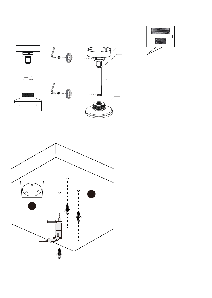
1. Select a suitable location where the camera is free from accidental damage, tampering,
or harsh environmental conditions.
2. Locate a place for the installation where the camera can not be intentionally or
unintentionally interfered.
3. Select a solid and at mounting surface that can support the combined weight of the
camera and associated hardware. Vibration and temperature range should also be taken
into consideration.
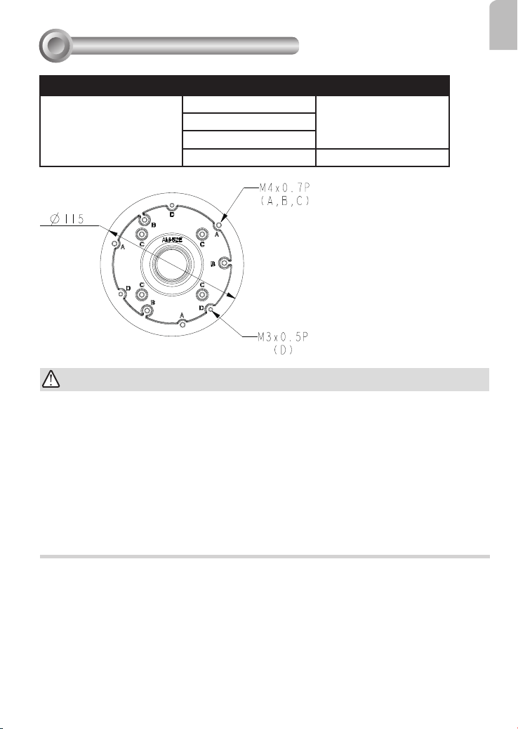
Compatible VIVOTEK Cameras
1
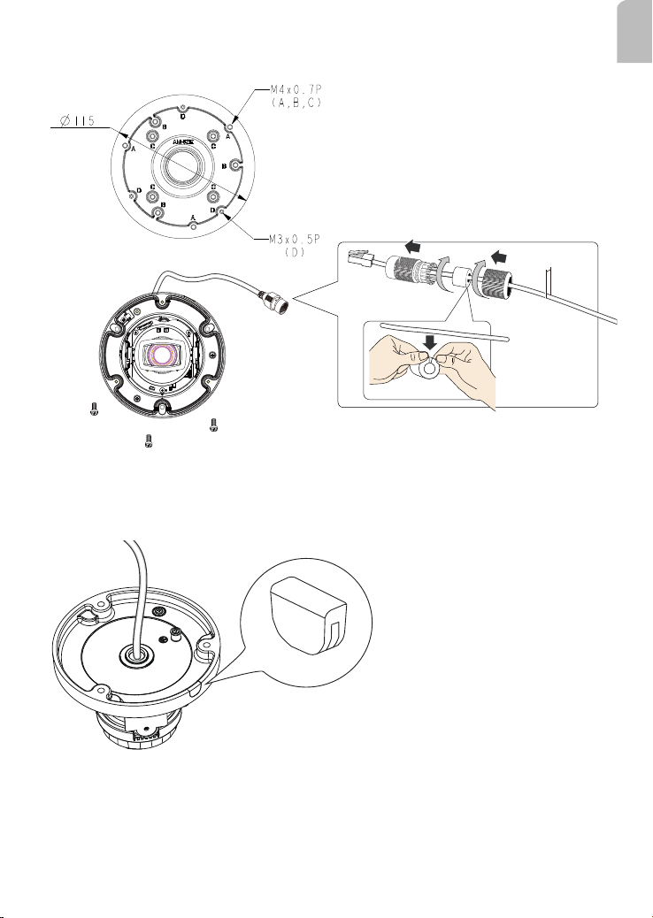
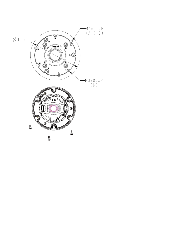
Combination Compatible Models Screw
Direct installation:
AM-118/114 + AM-117/116
+ AM-52E
A: FD9360-H, FD9380-H M4x8
B: IT9388-HT
C: IT9360-H, IT9380-H
D: IT9389-H, IT9389-HT M3x8