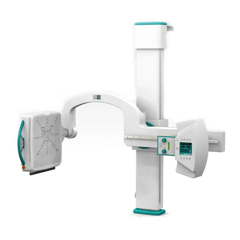
Viztek Ultra U-Arm User manual

Ultra U-arm Installation Guide v2.2
1
VZUG0014201508-2.2 Customer Support
Ultra U-Arm Install Guide

Ultra U-arm Installation Guide v2.2
2
VZUG0014201508-2.2 Customer Support
Table of Contents
PANEL SYSTEM PARTS:..................................................................................................4
STAND INSTALL:...............................................................................................................5
GENERATOR INSTALLATION:......................................................................................10
THREE PHASE GENERATORS .................................................................................................11
PANEL INTERFACE WIRING:........................................................................................13
WIRING LAYOUT ....................................................................................................................13
GENERATOR JUMPER CONFIGURATION:................................................................16
JUMPERS TO BE INSTALLED IN THE GENERATOR..................................................................16
GENERATOR TECH SERVICE CONFIGURATION: ..................................................17
WORKSTATION SETUP............................................................................................................17
EXTENDED MEMORY SETUP ..................................................................................................18
GENERATOR AUTO CALIBRATION ............................................................................19
STAND CALIBRATION .....................................................................................................21
POSITIONER CALIBRATION....................................................................................................22
HEIGHT CALIBRATION...........................................................................................................22
ARM ANGLE............................................................................................................................23
DETECTOR CALIBRATION......................................................................................................23
SID CALIBRATION..................................................................................................................24
PANEL SETUP AND CALIBRATION: ............................................................................25
AEC CALIBRATION –SEDECAL GENERATOR.........................................................30
CALIBRATION SETUP: ............................................................................................................30
LAUNCH ULTRA USER APPLICATION ....................................................................................30
ANTI CRUSHING VERIFICATION AND ADJUSTMENTS.........................................35

Ultra U-arm Installation Guide v2.2
3
VZUG0014201508-2.2 Customer Support
GENERATOR J4 WIRING.................................................................................................36
TROUBLESHOOTING ...............................................................................................................36
INSTALL GUIDE CHECKLIST........................................................................................37
TESTING AND CHECKS TO COMPLETE PRIOR TO APPLICATIONS ARRIVAL 39

Ultra U-arm Installation Guide v2.2
4
VZUG0014201508-2.2 Customer Support
Panel System Parts:
1 - 24v Viztek Power Supply
1 - Female to Female Serial Cable (Interface Cable from Power Supply to PC)
1 - DB9 to DB15 Cable (Panel to Power Supply)
1 - DB9 to Barrel Connector (Generator J4 to Power Supply)
1 - 75’ Network Crossover Cable (Panel to PC)
1 - 215 Line, 8:1 Grid possibly with Frame (Not Shown)
1 - USB to Serial adapter
1 –Computer Supply Cable
**Make sure all components are present**
Note: Viztek does not use the On/Off board provided with the generator.

Ultra U-arm Installation Guide v2.2
5
VZUG0014201508-2.2 Customer Support
Stand Install:
1. With the Positioner on the Pallet, carefully remove the wrapping from the Tube-Collimator
Support. This part includes the Positioner Control.
Unpack tube mount
2. Install the Tube-Collimator Support to the Upper Carriage of the Swivel Arm using the four screws
pre-attached to the Upper Carriage (torque 20Nm/ 177 Lbf.in). Note that the Positioner is still on
the shipping pallet.
3. With the Column still laid on the Pallet, install the Wall Support to the top of the Column with the
screws, washers and nuts provided.
4. Place the Column standing-up and position it at its final site in the room. While one person is
holding up the Column, the other one should level it vertically on both lateral sides and on the
front.

Ultra U-arm Installation Guide v2.2
6
VZUG0014201508-2.2 Customer Support
5. Anchor the Wall Support to the wall.
6. Perform the leveling adjustments on Column Base and on the Column Upper Support. Make sure
that the Column is correctly leveled and firmly tighten. Anchor the Column Base to the floor.
7. Place the Control Box on its final position of the room, keep in mind:
The length of the Column Harness (approx. 1.5m - 59”) that goes from the Column to the
Control Box.
The length of the High Voltage Cables (X-Ray Tube HV Transformer in the Generator
Cabinet).
The Swivel Arm movements.
8. Level the Control Box using the Adjustable Leveling Legs. Keep the Base at the maximum distance
from the floor.
9. Usually the Generator Cabinet is installed on top of the Control Box. (Make sure to run the 5’ J5
to Generator cable for positioned sync.)
10. Leave a working area around the Generator Cabinet until its final installation.
11. Perform the corresponding connections from the Column (Main Harness) in the Control Box.
12. Remove the Positioner Control (Monitor) from the Support of the Tube Collimator Support, for
that, unscrew the four fixing screws and carefully leave it resting on the Carriage Arm.
13. Position the X-Ray Tube on the Tube-Collimator Support and fix the X-Ray Tube to the Support
using the Collimator Adaptation Ring (this part is located in the Collimator Box and it is attached
to the Collimator window). The front will be marked with an “F”

Ultra U-arm Installation Guide v2.2
7
VZUG0014201508-2.2 Customer Support
14. Re-install the Positioner Control (Monitor).
15. Pull the Lever of the Tube-Collimator Assembly and carefully turn the Tube-Collimator Assembly
upside down (180o), this will facilitate the Collimator installation.
16. For the collimator to rotate to position "Ø", two of the four tabs retract to allow to rotation.
Adjust and tighten the four Allen screws as follows: screws 1 and 3 = 6½ turns (tight); screws 2
and 4 = 5½ turns exactly; Please Note: If Allen screws "2" and "4" are tightened more than 5½
turns, the collimator will not rotate.
17. Pull the Lever to turn the Tube-Collimator Assembly back to operating position.
18. Connect HV Cables in the X-ray Tube.
19. Remove cover at back of tube support. Connect the SID cable rolled up in a bag at the upper
carriage tube support. (pins 3,4, &5 on the terminal strip on back of tube support)
20. Connect Stator/Thermostat Cables in the X-ray Tube.

Ultra U-arm Installation Guide v2.2
8
VZUG0014201508-2.2 Customer Support
21. Route the cables connected to the X-ray Tube to the Generator. Fasten the Stator and HV cables
to Upper Carriage of the Swivel Arm with the Clamp at its lateral side.
22. Turn the Unit ON with the Switch located at the Control Box door.
23. Then remove the Safety Locking Rod from the Central Carriage.
24. Position the Swivel Arm at a comfortable position for installing the Detector.
25. Turn the Unit OFF with the Switch located at the Control Box door.
26. Before installing the Detector Assembly in the Delta Support, route the Detector Cables through
the Swivel Arm as indicated below. (Panel power cable and Cat5)

Ultra U-arm Installation Guide v2.2
9
VZUG0014201508-2.2 Customer Support
27. Remove the covers of the Detector Assembly.
28. Remove the 8 screws attached to the Delta Support.
29. Pick up the Detector assembly support and guide all the cables through its hole to install the
Detector Assembly Support on the Delta Support.
30. Install the Detector Assembly in the Delta Support of the Swivel Arm with its fixing screws.
31. Connect the Detector cables and Assembly cables to the respective connections of the Detector.
32. Check that all controls and movements operate correctly.
33. Turn the Unit OFF with the Switch located at the Control Box door.
34. Install the Base and Top Covers of the Column with the supplied screws.
35. Route, to the upper cable access of the Generator Cabinet, the cables from the Column to be
connected in the Generator (HV Cables, Stator/ Thermostat, if applicable AEC and Bucky signal
cables).

Ultra U-arm Installation Guide v2.2
10
VZUG0014201508-2.2 Customer Support
Generator Installation:
Prior to beginning installation, inspect the site and make sure that the X-ray room complies with Pre-
installation requirements, such as:
• Incoming Line Power.
• Main Switch and Safety Devices.
• Conduits.
• Space Requirements.
Make sure U24 chip is for Vizion (b39)

Ultra U-arm Installation Guide v2.2
11
VZUG0014201508-2.2 Customer Support
Three Phase Generators
1. For Three Phase Generators, connect the Power wires L1, L2 and L3 to the Fuse Holders of F3, F4
and F5 (right side of the Cabinet), and the Ground wire to the Ground Studs in the Cabinet Frame
(located above these fuses or close to the right side of the HV Transformer).
2. According to the nominal voltage of the line, make sure or connect the wire “:” to the indicated
terminal (TB) of Transformer 6T2. This wire is factory connected to 230 VAC (for 1-Phase), 400
VAC (for 3-Phase) or 480 VAC / 530 VAC (for 80 kW 3-Phase Generators).
3. Check 6T2-4 for low speed rotor only generators with Toshiba tubes is wired for 110vac/120vac.
When routing cables, take notice of cover mounting.

Ultra U-arm Installation Guide v2.2
12
VZUG0014201508-2.2 Customer Support

Ultra U-arm Installation Guide v2.2
13
VZUG0014201508-2.2 Customer Support
Panel interface Wiring:
Wiring Layout
75’ Cat5 cable runs from Panel to PC.
50’ Female to Female serial cable runs from Panel power box to USB to Serial adapter on PC.
DB9 to Round 5 pin Barrel connector runs from Generator J4 to Panel power box.
BD15 to BD9 runs from Panel to Panel power box (Panel power cable)
A total of 4 cables are needed to be interface between room and tech control area. A Cat 5 crossover
cable from panel, a 50’ F-F serial cable from Power Supply, a Mini Console J5 cable from generator (Stand
power box with U-arm), and the Mini Console ground from generator.
To PC
J4 Plug
Generator
Panel
USB to Serial
PC
NIC Card
50’ Serial
Cable
Power
Supply
DB9 to Barrel
Cat 5 crossover
To panel
The Crossover cable
will run from the Panel
to the PC in the tech
area.
The Panel uses the
Onboard NIC Card IP:
192.168.37.131
DB 15
panel to
DB9
Power
Supply

Ultra U-arm Installation Guide v2.2
14
VZUG0014201508-2.2 Customer Support
DB9 to Barrel Connector
will run from J4 in the
Generator to the Power
Supply box marked for
24VDC.
If J4 is not in system go to
page 32 for hard wiring in
the connection.
To Generator
J4 In Generator
To PC
USB-Serial
DB9 to DB9 serial cable will run
from Power Supply to USB to Serial
adapter on PC

Ultra U-arm Installation Guide v2.2
15
VZUG0014201508-2.2 Customer Support
To P.S.
PP
To Panel
****Detector Interface may be
different depending on detector.
DB9 to DB15 cable
will run from Panel
(15 pin) to Power
Supply (9 pin).
Both DB9 plugs are
24VDC, only one is
used unless multiple
panels are being
installed.

Ultra U-arm Installation Guide v2.2
16
VZUG0014201508-2.2 Customer Support
Generator Jumper Configuration:
Jumpers to be installed in the Generator
3TS1-2 to 3TS1-7AEC and Adapt board TS1-7 to TS1-10
Install Jumper from 3TS1-22 to 3TS1-23 as needed for
Door Interlock
Make sure SW2-3 on ATP Board is in Service Mode
(page 3 of Configuration Section of the Generator
Service Manual)
Make sure U24 chip on ATP Board is V7R1b39 version

Ultra U-arm Installation Guide v2.2
17
VZUG0014201508-2.2 Customer Support
Generator Tech Service Configuration:
Workstation Setup
1. From the PC (MPU), select the shortcuts window, then select TechService. The Generator Service
Mode screen displays.
Figure 1
2. On Generator Service Mode screen, choose Configuration. The Configuration screen displays. Figure
22
a. WS1 must be set as:
Tube 1, Bucky 1, and which port you have selected for AEC.
b. WS3 must be set as:
Tube 1, Direct, and which port you have selected for AEC.

Ultra U-arm Installation Guide v2.2
18
VZUG0014201508-2.2 Customer Support
Extended Memory Setup
Complete the following steps:
oSelect MANUAL CALIBRATION
oSelect past the highest mA station.
oE02: Tube Type = (Tube chart on page 39 of the configuration tab in the generator manual)
FX7254 = 5, FX7884 = 6
oAEC Calibration = 70
AEC-J1 calibration = E04
AEC- J2 calibration = E09
AEC- J3 calibration = E20
oE06: KV Compensation = 200
Extended Memory Location E06 contains the calibration factor for kV Loop. Each
number above or below of the indicated in the E06 memory location increases or
decreases respectively the kV gain value.
oAEC Tracking
AEC- J1 tracking = E08
AEC- J2 tracking = E10
AEC- J3 tracking = E24
YOU ARE NOW READY TO CALIBRATE THE GENERATOR

Ultra U-arm Installation Guide v2.2
19
VZUG0014201508-2.2 Customer Support
Generator Auto Calibration
Complete the following steps:
1. Select Auto Calibration.
2. Select workstation (WS3 / Direct mode).
3. Angle Tube away from detector.
4. Click OK.
5. Confirm or leave the Auto-calibration by pressing the respective button (Yes or No)on the
new screen.
6. Select focal spot calibration. (Figure 23 left)
7. Click OK.
8. Select Yes, i.e., (Figure 23 right).
Figure 23 Figure 23
9. Confirm or leave the Auto-calibration (second confirmation) by pressing the respective
button (Confirm or Dismiss) on the calibration screen. (Figure 24)
10. Auto-calibration is activated when the AutoCalibration is displayed. (Figure 25)

Ultra U-arm Installation Guide v2.2
20
VZUG0014201508-2.2 Customer Support
Figure 24
Figure 25
11. Press Prep and Expose from the hand switch. (Prep may take up to 45 seconds to start
Calibration).
12. AutocalOK replaces AutoCalibration when the calibration is completed for the selected
focal spot.
13. Spot check generator for calibration verification. (E06 can be adjusted for proper cal.)
Other manuals for Ultra U-Arm
1
Table of contents
Other Viztek Medical Equipment manuals
Popular Medical Equipment manuals by other brands
Hologic
Hologic CYNOSURE ELLMAN SURGITRON 4.0 Dual RF/90 IEC instruction manual
Hospira
Hospira Micro Macro plum XL System Operating Manual

uniprox
uniprox JT40 instruction manual

Amico
Amico S-AM1-300X Operation & maintenance manual

DAESUNG MAREF
DAESUNG MAREF CTC-7 user manual

Invacare
Invacare ISA COMPACT user manual

EKF Diagnostics
EKF Diagnostics DiaSpect Tm user manual

Stryker Medical
Stryker Medical Renaissance Series Maintenance manual
futudent
futudent Novocam Instructions for use

Oridion
Oridion Smart OmniLine Guardian Directions for use
Lowenstein Medical
Lowenstein Medical prisma20C manual
Stryker
Stryker FL28C Operation manual
