VKAR Bison User manual

VKAR Hobby Co.,Ltd
WWW.vkarracing.com
INSTRUCTION MANUAL
1:10 Scale Electric 4WD Off Road Race Truggy

Bright LED light.Secure wheelie bar set.
All rubber covered bearing throughout.
.
Adjustable rear wing.
Sealed,tunable limited-slip differentials.
All terrain tires & agreessive electroplate wheel.
Oil-filled ultra AL shocks with progressive dual-springs.
Fully assembled and Ready-To-Run.
.
Thank you for purchasing VKAR product.This manual contains instructions
on operating and maintaining the Bison .Please take a monent to read
through this manual to familiarze yourself with this model.
Tools lncluded
Requires
11
INTRODUCTION
532mm
380mm
218mm
330mm
Charger
Transmitter
Hex Key
4 PCS AAA Batteries
(For Transmitter)
Scale:1/10
Drive System:4WD
Power Battery
FEATURES
PRODUCT CONTENTS
22
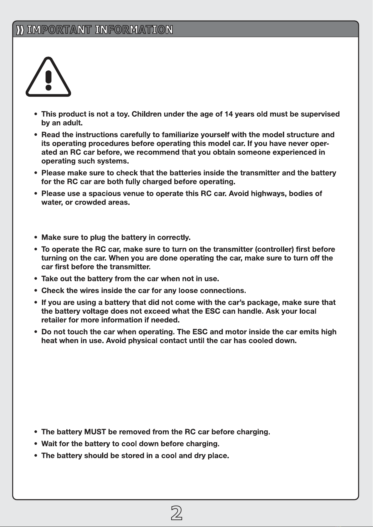
IMPORTANT INFORMATION
The Bison is a powerful RC car that will bring much
enjoyment.Howewever,improper use can cause damage
and bodily injuries.Please read the following information
carefully to avoid casualties.
This model can be operated with Ni-MH or Lithium Polymer
batteries. Due to the battery’s high energy,density,please pay
attention to the following information to avoid injuries or
damages.
WARNING:
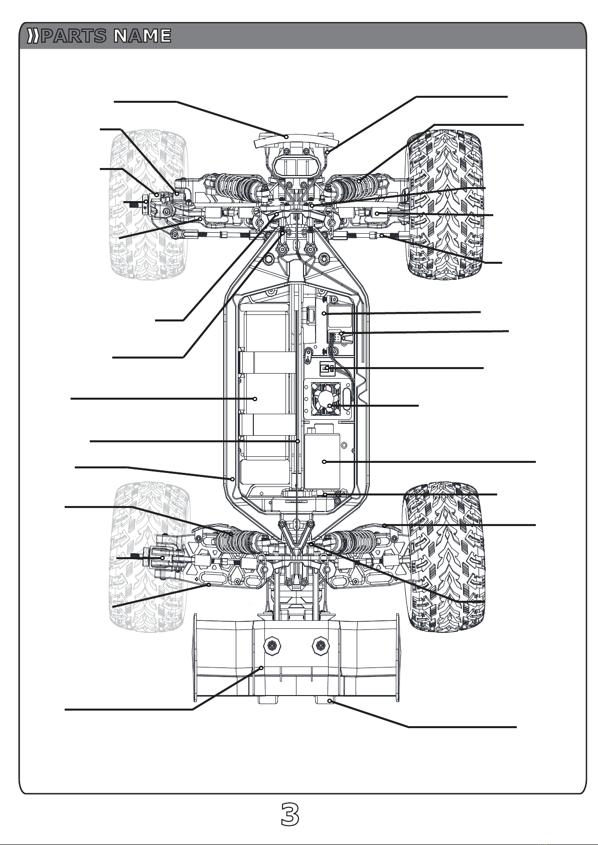
Front Bumper
Hub Carrier
Steer Block
Wheel Hex Hub
Body Mount Bracket
Chassis
Battery
Rear Hub Carriers
WING
Motor
Electronic Speed Control
Receiver
Turnbuckle
(toe Link)
Tailwheel
Shock
Front Shock Stay
Suspension Arm
Shock
Rear Shock Stay
Motor Mount
33
Support Bracket
Power Switch
Steering Servo
Turnbuckle
(Camber Link)
LED Light
Fender
Suspension Arm
Center Shaft
PARTS NAME

SYSTEM INSTRUCTION
4
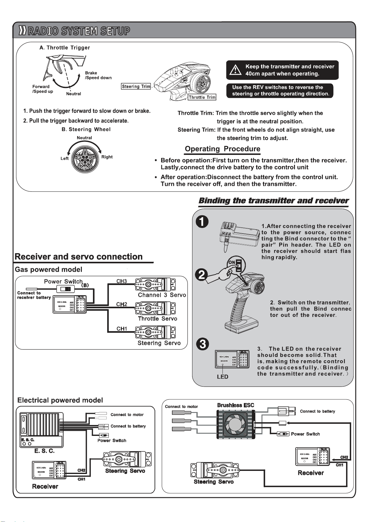
RADIO SYSTEM SETUP
5

【BEGIN TO USE THE NEW ESC】
1. Connect the ESC, motor, receiver,
battery and servo according to the
following diagram
“+”and “-”wires of the ESC are
connected with the battery pack, and #A,
#B and #C are connected with the motor
wires. The “SET”button is used for
programming the ESC.
The control cable of the ESC (trio wires
with black, red and white color) is
connected with the throttle channel of the
receiver (Usually CH2).
1The #A, #B, #C wires of the ESC can be
connected with the motor wires freely
(without any order). If the motor runs in
the opposite direction, please swap any
two wire connections.
Note: You can use the transmitter to
set the throttle channel to
the“Reverse”direction, and then the motor will run oppositely. Please calibrate the throttle range again
after changing the direction of throttle channel.
2. Throttle Range Setting (Throttle Range Calibration)
In order to make the ESC match the throttle range, you must calibrate it when you begin to use a new ESC, or a
new transmitter, or after changing the settings of the neutral position of throttle channel, ATV or EPA parameters,
otherwise the ESC cannot work properly.
There are 3 points need to be set, they are the top point of
“fo
rward”,”
backward”and the neutral point.
The following pictures show how to set the throttle range with a FutabaTM transmitter.
Note2: If you don’t release the “SET”key after the
red LED begins to flash, the ESC will enter the
program mode, in such a case, please switch off
the ESC and re-calibrate the throttle range again
from step A to step D.
A) Switch off the ESC, turn on the
transmitter, set the direction of throttle
channel to ”REV”, set the “EPA/ATV”
value of throttle channel to “100%”, and
disable the “ABS”brake function of
your transmitter. (*Note2)
B) Hold the “SET”key and then switch on
the ESC, when the red LED begins to
flash, release the key immediately.
(Please check the picture on the right side)
C) Set the THREE points according to the
steps shown in the picture on the right
side.
1) Neutral point
2) End point of forward direction
3) End point of backward direction
D) When the process of calibration is
finished, the motor can be started after
3 seconds.
SETUP
6

3. The LED Status in Normal Running
a) When the throttle stick is in the neutral range, neither the Red LED nor the Green LED lights up.
b) When the car moves forward, the Red LED solidly lights; the Green LED also lights up when the throttle stick is
at the top position (100% throttle).
c) When the car brakes, the Red LED solidly lights; the Green LED also lights up when the throttle stick is at the
bottom position and the maximum brake force is set to 100%.
d) When the car reverses, the Red LED solidly lights.
【ALERT TONES】
1. Input voltage abnormal alert tone: The ESC begins to check the input voltage when power on, if it is out of the
normal range, such an alert tone will be emitted: “beep-beep-, beep-beep-, beep-beep-”(There is 1 second
time interval between every “beep-beep-”tone).
2. Throttle signal abnormal alert tone: When the ESC can’t detect the normal throttle signal, such an alert tone
will be emitted: “beep-, beep-, beep-”(There is 2 seconds time interval between every “beep-”tone).
【PROTECTION FUNCTION】
1. Low voltage cut-off protection: If the voltage of a Lipo battery pack is lower than the threshold for 2 seconds,
the ESC will cut off the output power. Please note that the ESC cannot be restarted if the voltage of each Lipo
cell is lower than 3.5V.
For NiMH battery packs, if the voltage of the whole NiMH battery pack is higher than 9.0V but lower than 12V,
it will be considered as a 3S Lipo; If it is lower than 9.0V, it will be considered as a 2S Lipo. For example, if the
NiMH battery pack is 8.0V, and the threshold is set to 2.6V/Cell, it is considered as a 2S Lipo, and the
low-voltage cut-off threshold for this NiMH battery pack is 2.6*2=5.2V.
2. Over-heat protection: When the temperature of the ESC is over a factory preset threshold for 5 seconds, the
ESC will cut off the output power. You can disable the over-heat protection function for competition race.
3. Throttle signal loss protection: The ESC will cut off the output power if the throttle signal is lost for 0.2 second.
7
SETUP
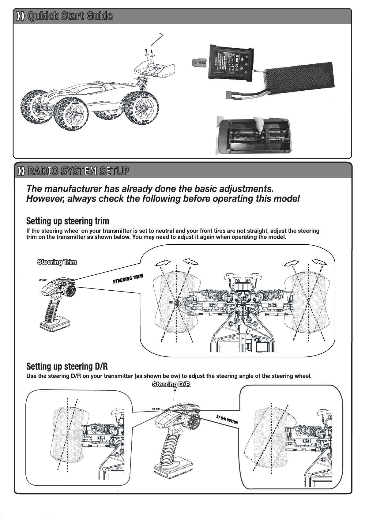
Steering angle
is more
Steering angle
is less
2. Charging the Battery
3. Loading the Battery
1. Wing Assembly
Quidck Start Guide
RADIO SYSTEM SETUP
8

9
47
46
45
48
50
52
51
55
54
52
50
51
49
49
170
56
170
46
47
M2.5x12
10x15x4mm
10x15x4mm
103
99
98
96
57
31
102
101
100
5x10x4mm
4mm
5x10x4mm
M3x3mm
M2.5x8mm
101
4mm
97
102
9
Differential Assembly
Front Driver Shaft Assembly
CORRECT WRONG

10
107
108
109
98
31
103
108
107
110
98
104
105
106
98
97
96
47
3.5mm
M2.5x8
5x10x4mm
5x10x4mm
M3x3mm
11T
Rear Driver Shaft Assembly
TIPS:The slipper clutch adjstment short cut
Use 1.5mm hex key,Insert the hold as the picture below.
Grasp the both sides of rear wheels,rotate in the same direction.
Adjusting the Slipper clutch
NOTE: the slipper clutch adjustment too loose or tight
may result in damsge the gear during racing.
M2.5x8
SW201
M2.5x12
SW201
10x15x4mm
BB103
8x12x3.5mm
BB104
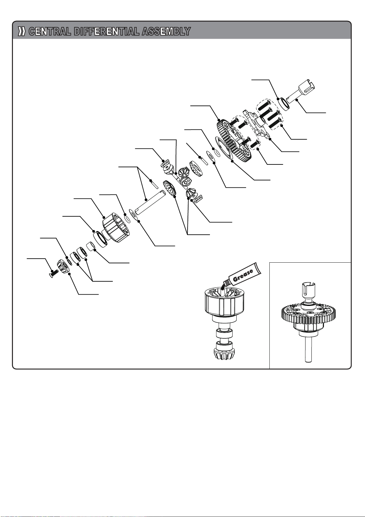
CENTRAL DIFFERENTIAL ASSEMBLY
ET1088
OR102
ET1091
ET1091
ET1096
ET1088
ET1081
ET1093
SH102
5X10X4
BB1102
OR102
ET1090
M2.5x8
SW201
SH103
5X12X0.3
SH103
5X12X0.3
SH101
2.5X7X0.3
ET1082
AC001
MA328
ET1092
2.0X8.8
2.0X8.8
11

M3x15
160
109
12
156
157
160
159
158
41
41
31
161
4
4
33
4
118
69
101
60
4
41
41
102
124
123
121
132
120122
124
121
119
33
117
115
116
5x8x2.5mm
5x8x2.5mm
5x8x2.5mm
5x8x2.5mm
121
69
4.0mm
M3x20mm
M3x20mm
M3.0mmM3.0mm
M3x10mm
M3x10mmM3.0mm
M3.0mm
M3x8mm
Steering Assembly
Motor Mount Assembly
NOTE: Rotating the nut 115 to seek
suitable degree of tightness.
NOTE: Rotating the nut 115 to seek
suitable degree of tightness.
NOTE: Look out the interval between motor gear 161
and spur gear 109 if the screw is loosened 160 please adjust it.
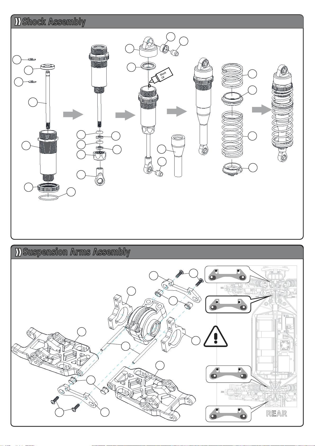
1.Fill shock body with 4/5 silicone fluid(purchase seperately),pump the shock shaft
up and down to remove any air bubbles.
2.Wait the air bubbles pumped out,then pull down the shock shaft to the bottom,fill
the silicone fluidup to 2 mm,after that,tighten the shock head1.
3.Install the spring,shock assemblingfinished.
Shock Aaaembling Steps:
FRONT
REAR
13
12
13
22
23
7
7
12
1
3
2
16
11
910
10
3
11
15
24
19
18
5
9
43
13
61
61
44
28
43
13 41
28
41
Shock Assembly
Suspension Arms Assembly
NOTE:Pay attention to choose
the right hole when installing

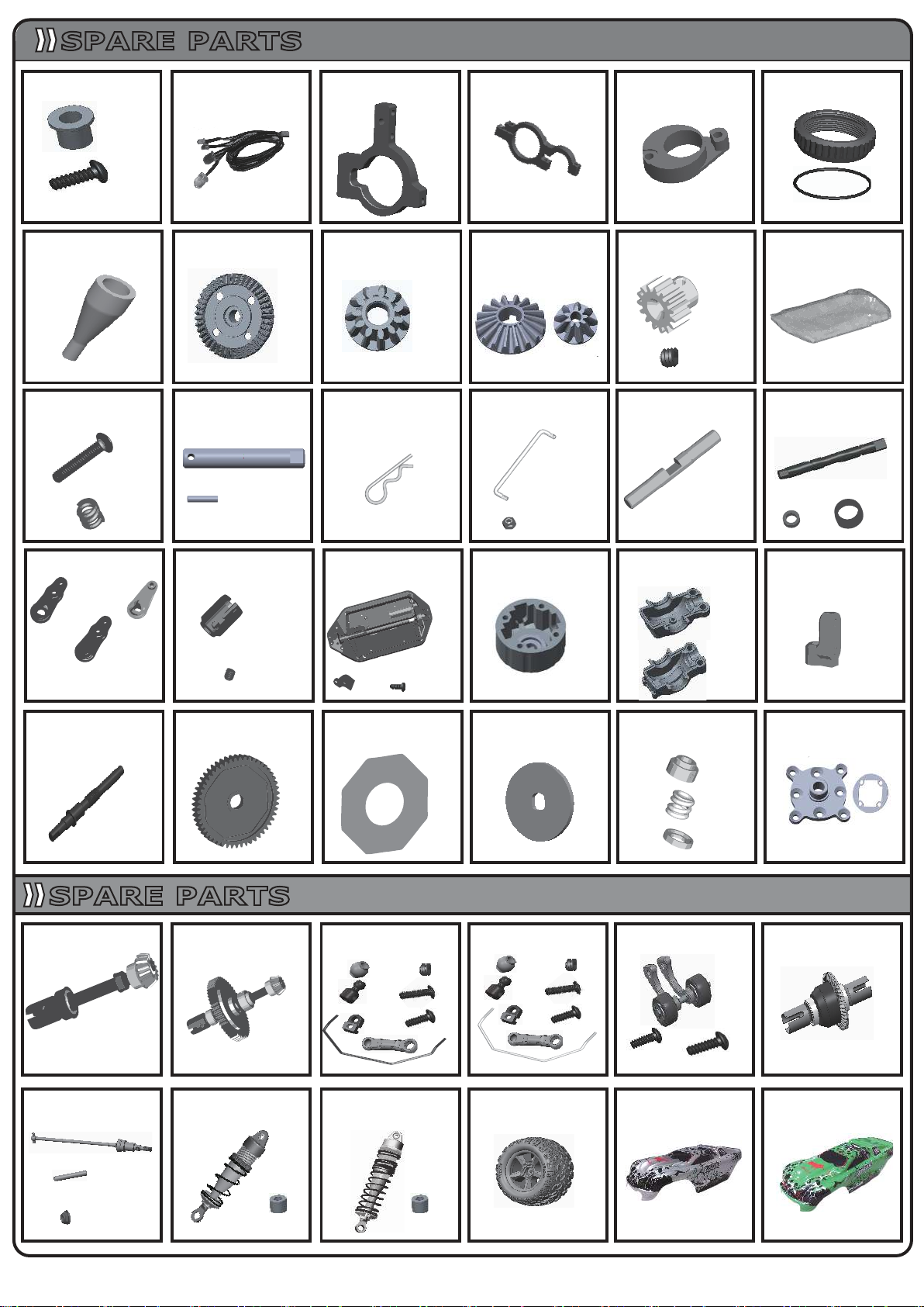
ET1001 ET1002 ET1003 ET1004 ET1005 ET1006
ET1007 ET1008 ET1011
Front
Rear Front Rear
ET1012
ET1013 ET1014 ET1015 ET1016 ET1017 ET1018
ET1019 ET1020 ET1021 ET1022 ET1023 ET1024
ET1025
ET1041
ET1029 ET1030
ET1031 ET1033 ET1034 ET1035 ET1036
ET1037 ET1038 ET1039 ET1040
x6
x2
x1
x1
x2
x1
x3 x8
x4
M3x8
M3x8
M3x10
x2
x2
x1
Front
x2 x2
ET1028
x1
x4
SPARE PARTS
ES1022 ET1010
x1
x1
x1
x1
x4
x4
M3x8
x1
x1
ET1026 ET1027
x2
ET1032
x4
x1 x1
x2 x2
x4
x1
x1
x4
Rear
x1
x2
x2
x2
x2 x2
x2
x2 x2
x2
x1
6.8mm 6.8mm 5.8mm
x2
x1
x1
M4X10
Left
Right Right
Left
Front Rear
Left
Right
x2
x1 x1
x1 x1
x1
x1 x2
x1
x1
x2
x2
x2
x2
x2
x2 x2
M4x10
M3x6
M3x8 M3x10
M3x8
M3x15
x1
x1
x1
x2
x2 x2
x2
x2
x2
x2
x2
x2
x2
x2
x1
x4
x1
x1
x4
x2
x2
x2
3x46mm
3x40mm
Front
Rear
x2
x2
x2x2
ET1042
x1
x1
M5
M5X85
x2
x2
M3x16
x2 x2
M4x15
x1
YELLOW
2X16.8
20X225
14
ES1001 ES1002 ES1003
ET1043 ET1044
ET1045 ET1046 ET1047
SPARE PARTS
ET1082
MA311
MA316
MA319
MA320 MA321 MA328 MA330
MA331
ET1095
MA337
ET1084 MA349 MA350
MA354-B
MA355 MA357
MA358
ET1098 ET1099
x1
x1
x1
x1
x1
x10 x2
x1
x2 x1 x1
x1
x1
x1
x1 x2
x1
x1
x2
x1
x1
x1
x1 x2
x1
x1
x1
x2
x1
x1
x1
x1
x4
x4
x2 x2
x1
M3x16 M4x15
x4x2
x2
x2
x2
x2
x2
x1
Front
x2
x2
x2
x2
x1
Rear
ET1049
ET1048
M4x12
M3x16
M3x16
M3x8 M3x8
ET1052
x2
ET1050 ET1051
x1 x1 x1
2x16.8
M5
x2
x2
x1 x1
SPARE PARTS
x1
x4
x2
x2
Front Rear
x1 x1 x2
x1
x1 x1 x2 x4
x1
x1
x1
Φ5
MA310B
x1 x1
ET1025S ET1025G
SILVER
GREEN
32T 11T
ET1080ES1046
ES1040
ET1081
ET1091
2*8.8mm
ET1092
15

16

Number Name Sp ec if ic ation Dosage Number Name Specification Dosage Number Name Specification Dosage
1 Hydraulic top button 1 4 58 Lower Deck-F 1 115 Saver Spring 1
2
Hydraulic ball head c overed
4 4 59 Box Post 4 116 Saver Spring 1
3 Universal _Ball 5.8 14 60 Screw M3x1 18 117 Servo Saver-B 1
4 Nylon Nut M3 8 61 Front Suspension Arm 2 118 Servo Saver-A 1
5 Shock_picston 4 62 Rear Suspension Arm 2 119 Steering Arm 1
6 Shock_body-F 2 63 PIN 3X40 4 120 Steer Post-R 1
7 E-Clip 2.5 8 64 Steer Holder L 1 121 Bearing 5X8X2 .5 4
8 Shock Shaft 2 65 Steer Block L 1 122 Steer Link 1
9 O-ring3x2 10 66 Steer Block R 1 123 Steer Post-R 1
10 Shock_Support 8 67 Steer Holder R 1 124 Sleeve 4.5 2
11 Shock_Cap 4 68 Kinpin Case 4 125 Bumper F 2
12 Shock Ring 4 69 Screw M3x20 6 126 Screw M4x20 2
13 O- Ring 16x1 4 70 Screw M4x12 4 127 Support Bracket F 2
14 Dust Cover 4 71 Push-pull Rod 2 128 Fender L 1
15 Slingshot stop 4 72 Ball Cup 24 4 129 Fender R 1
16
Hydraulic ball head buckle
4 73 Screw M3x15 2 130 Antenna Mount 1
17 6.8 Ball Screw B 2 74 Washer 3x6x2 4 131 Tube 1
18 Shock_Spring-S 4 75 CVD shaft 1 132 Main Chassis 1
19 Shock_Plastic Parts 4 76 PIN 2X12 1 133 Iron Center Shaft 1
20 Shock Spring-F 2 77 PIN 2X16.8 1 134 Gear Cover 1
21 Air Vessel 4 78 PIN 3X12.7 1 135 Bumper 1
22 Shock_Body-R 2 79 CVD Holder 1 136 Bumper 1
23 Shock Shaft 2 80 Fixed pin 1 137 Holder_L 1
24 Shock Spring-R 2 81 CVD Ring 1 138 Holder_R 1
25 Bumper 1 82 Wheel Hub 1 139 Holder 1
26 Bumper 1 83 Screw M3x16 16 140 Fixed dam 1
27 Bumper 1 84 Push-pull Rod 50 2 141 Wing 1
28 Screw M4X10 6 85 Rear Hub Carriers 2 142 Pressure_pad 2
29 Screw M3X8 26 86 Shock Stay-F 1 143 Screw M4x15 2
30 Screw M3X6 12 87 Nut M3 4 144 Rally_tyes 4
31 Screw M3x3 11 88 Washer 4 145 Tire Inner 4
32 Pressure_pad 4 89 Nut M3 8 146 Wheel 4
33 6.8 Ball Screw_C 2 90 Screw M3x23 4 147 Nut M5 M5 5
34 Front Anti-roll Bar 1 91 Ball Cup 34 8 148 6.8 Ball Screw_B 8
35 4.8_Ball-Sleeve 4 92 Body Mount Bracket-F 1 149 Magic Tape 2
36 Ball Cup 26 4 93 Spring Lock 4 150 LI-PO Battery 1
37 Rear Anti-roll Bar 1 94 Shock Stay-R 1 151 Sponge Block 1
38 Bulkhead 4 95 Body Mount Bracket R 1 152 Mantle 1
39 Gear Box 2 96 Differential gear 11T 2 153 Servfo Stay 2
40 Gear Box 2 97 Spacer 2 154 SERVO 9KG 1
41 Screw M3X10 28 98 Bearing 5X10X4 5 155 Servo_Arm 1
42 Arm Holder 4 99 Sponge Block 1 156 Motor 3660 2500KV 1
43 Pin Cap 8 100 Drive Shaft-F 1 157 Motor Mount-B 1
44 Pin 3x46 4 101 E-Clip 4.0 4 158 Motor Mount-A 1
45 Differential Housing 2 102 Bearing bush 1 159 Screw Spring 1
46 Bearing 10X15X4 12 103 Drive cup 2 160 Screw M5X85 1
47 CVD Holder 1 104 Slipper Screw 1 161 Motor Gear 1
48 2 105 Saver Spring 1 162 Receiver 1
49 O_Ring 4.5x1.5 4 106 Pre Ring 1 163 ESC 60A 1
50 Spacer 5X12X0.3 4 107 Driver Disc 2 164 Post 2
51 PIN 4 108 Slipper Sheet 2 165 Painted Body 1
52 Differential gear 18T 4 109 Spur Gear 52T 1 166 LED 1
53 Spacer 2.5x7x0.2 8 110 Driver Shaft-R 1 167 Tail Wheel Holder 2
54 Differential gear 9T 8 111 Push-pull Rod 2 168 Tail Wheel 2
55 Differential pin 4 112 Lower Deck-R 1 169 Tail Wheel Holder 1
56 Drive the cone gear 32T 2 113 Servo Rod 1
57 Screw
Screw
M2.5x8 10 114 Ball Cup 16 2
Bill Of Material
170 M2.5*12
15T-Φ5
2.0X8.8
2
ASBESTOS CUSHION
17
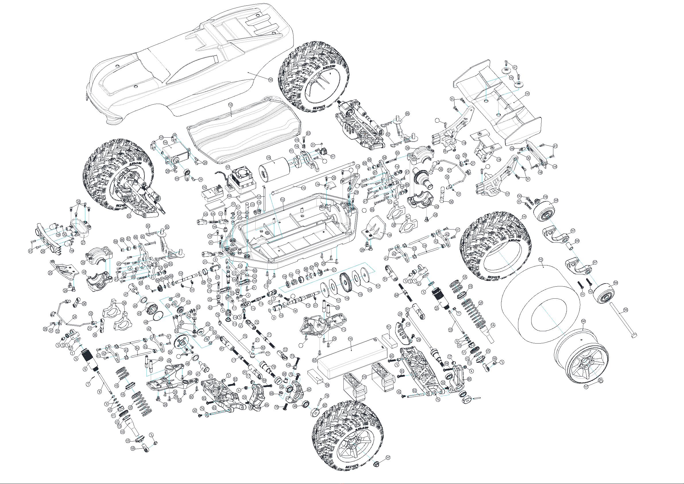
EXPLOED VIEW
170
29
29
41
41
60
41
41
18 19

Tel:0769-88039076
0769-88030083
Fax: 0769-81620956
Address:302,Building A,Yiben Industrial park,No.124 BBK road ,Usha community, Chang'an town,
Dongguan City,Guangdong Province,China 523860.
R
Other manuals for Bison
1
This manual suits for next models
1
Table of contents
Other VKAR Motorized Toy Car manuals


Popular Motorized Toy Car manuals by other brands

Reely
Reely "Cyclone" 4WD RtR operating instructions

Serpent
Serpent VIPER 990 instruction manual

HOMCOM
HOMCOM Lambo V12 Vision Gran Turismo Assembly instruction

Mattel Wheels
Mattel Wheels Tyco R/C STUNT PAK BARREL BLAST instructions

Kyosho
Kyosho EP JETSTREAM888 VE instruction manual

Aosom
Aosom 370-259V00 quick start guide


