VL Audio VL-20000Q User manual

VL-20000Q
POWER AMPLIFIER CLASS TD
USER MANAUL
WWW.VL.CO.TH
AChannel
-10dB
0-inf
BChannel
-10dB
0-inf
CChannel
-10dB
0-inf
DChannel
-10dB
0-inf
SIG -20 -15 -10 -4 VPL CPL
SIG -20 -15 -10 -4 VPL CPL
VHF
PWR
PAL
TEM
MUTE
CLIP
HI-IMP
BRIDGE A+B
CLIP
HI-IMP
VHF
TEM
SIG -20 -15 -10 -4 VPL CPL
SIG -20 -15 -10 -4 VPL CPL
VHF
TEM
MUTE
CLIP
HI-IMP
BRIDGE C+D
CLIP
HI-IMP
VHF
TEM
NOMAD
LINK

1USER MANAUL
DESCRIPTIONS
For decades, the Class AB output stage set a standard for high
quality sound amplifiers. Although Class AB amplifiers are known for
their superior sound quality, they do not make efficient use of power.
The output stage generates a lot of heat and requires huge heat sinks
and fans to ensure that the output transistors inside the amplifier are
at a safe temperature. In order to achieve high power, a larger power
supply is required, but eventually most of the power becomes hot.
At the core of the VL-20000Q performance is the Class TD output
stage a breakthrough amplifier topology that approaches the exceptional
efficiency of Class D while retaining the sonic purity of proven Class B
Class TD is bridgeable, highly reliable, and maintains a flat response
with complex loads as low as 2 ohms nominal. Also, it does not interfere
with RF equipment such as wireless (radio) microphones. Though
treated separately here, R.SMPS and Class TD were conceived and
engineered as an integral design within the amplifier platform.
Designs. Remarkable efficiency of the VL-20000Q is a Regulated
Switch Mode Power Supply (R.SMPS), which gives theadded benefit
of stabilizing rail voltages to the output even with wide fluctuations
of mains voltage.
The VL-20000Q power amplifier class TD from VL Audio. 4-channel
10,400 Watt high power that is low in heat. Dissipation. High wattage,
durable, strong, light weight Used for touring events, concerts or
installations.
INTRODUCTION
FEATURE
• Current Average Limiter
• Current-Clip Limiter, Direct Current Protection (DC)
• Short Circuit Protection
• Very High Frequency Protection (VHF)
• Voltage Clip Limiter (VPL)
• Temperature protection
• Duo R.SMPS Power Supply
2USER MANAUL
1. Read all documentation before operating your equipment. Retain all documentation for further reference.
2. Mains voltage must be correct and the same as that printed on the rear of the unit. Damage caused by connection to improper
AC voltage is not covered by any warranty.
3. Always operate the unit with the AC ground wire connected to the electrical system ground. Precautions should be taken so that
the means of grounding of a piece of equipment is not defected
4. Connecting amplifier outputs to oscilloscopes or other test equipment while the amplifier is in bridged mode may damage both
the amplifier and test equipment.
5. Do not drive the inputs with a signal level greater than that required to drive equipment to full output.
6. Do not run the output of any amplifier channel back into another channel's input. Do not parallel or series connect an amplifier
output with any other amplifier output.
7. In system setup ‚amplifier's output power must be greater 50%-100% than the loaded loudspeaker's rated power.
8. Make sure the signal correctly connect to the amplifier's input channel at current input mode.
9. Please turn off the power switch ,when pull off the power cord and signal cable or select the input mode switch.
10. In typical use, Please set the volume to OdB position.
11. Sometime, one signal to more than one amplifier, suggest use signal distributor.
12. Please clean the dust filter , every 15 days.
Read all safety instructions before operating amplifier.
Install equipment as follows:
-- Install in a flat place, not bending or curved.
-- Do not install near water and moisture.
-- Place power amplifier away from heat sources, such as
radiators or other heat source.
Keep in mind the following when connecting amplifiers
-- Read the user manual before connecting the amplifier
-- Connect each connection of the amplifier perfectly. If not,
it may cause hum, damage, elec shock in case of disconnection.
-- To prevent electric shocks, do not open top cover.
Connect the power cord with safety after check fo AC power.
IMPORTANT: Use of controls or adjustments or performance of procedures other than
those specified herein may result in hazardous radiation exposure.
ATTENTION : RISQUE DE CHOC ELECTRIQUE - NE PAS OUVRIR
WARNING : TO REDUCE THE RISK OF FIRE OR ELECTIRC
SHOCK DO NOT EXPOSE THIS EQUIPMENT TO RAIN OR MOISTURE
IMPORTANT NOTES
SAFETY INSTRUCTIONS
CAUTION
RISK OF ELECTRIC SHOCK
DO NOT OPEN
3USER MANAUL
OVERVIEW
FRONT PANEL
AChannel
-10dB
0-inf
BChannel
-10dB
0-inf
CChannel
-10dB
0-inf
DChannel
-10dB
0-inf
SIG -20 -15 -10 -4 VPL CPL
SIG -20 -15 -10 -4 VPL CPL
VHF
PWR
PAL
TEM
MUTE
CLIP
HI-IMP
BRIDGE A+B
CLIP
HI-IMP
VHF
TEM
SIG -20 -15 -10 -4 VPL CPL
SIG -20 -15 -10 -4 VPL CPL
VHF
TEM
MUTE
CLIP
HI-IMP
BRIDGE C+D
CLIP
HI-IMP
VHF
TEM
NOMAD
LINK
4
5
6
89
7
3 12
1413
11
10 12
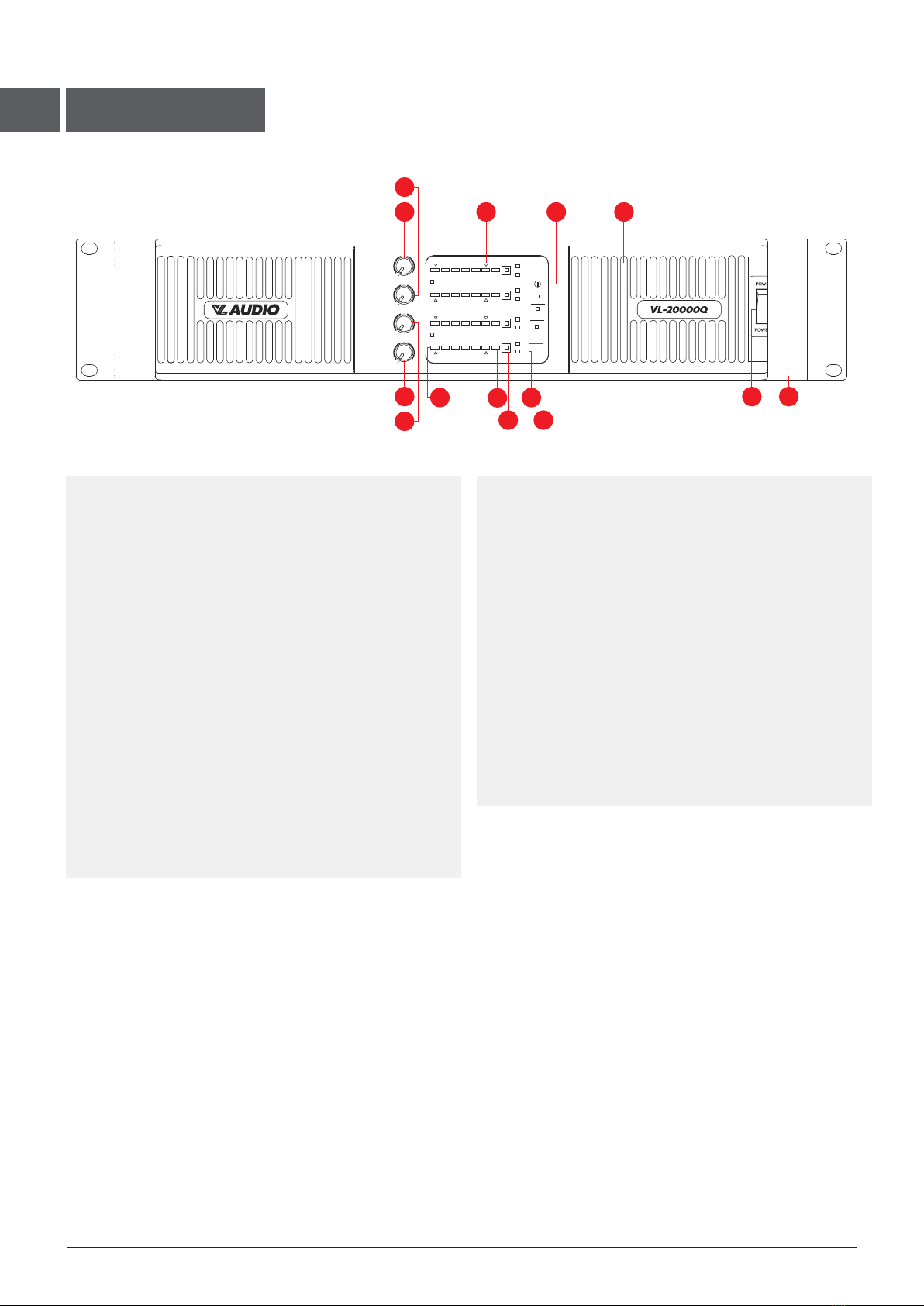
1 AIR ENTRANCE
This part is the air entrance. Don't obstruct It.
2 “POWER”(PWR) INDICATOR
This indicator lights when the power amplifier is switching on.
3 “CLIP”(VPL) INDICATOR
Any illumination of the clip indicates a state of over
modulation (distortion at extremely high volumes). In
this case, check the output signal of your mixer and
turn down the input gain control. Please keep in mind
that the power amplifier connot correct any distortion.
4-7 CHANNEL A - CHANNEL D VOLUME CONTROL
In stereo mode, this potentiometer allows the adjustment
of the channel A-channel D input level.
8 “SIGNAL” INDICATOR
Signal levels -20dB (Sig) to -4 dB.
9 “CPL” INDICATOR
Current Peak Limiter (CPL) active (Orange flashing).
10 “PRORECTION” INDICATOR
When this indicator lights, that means the power amplifier
is in the protection mode. Switch off the device and find
out the problem. This power amplifier is protected overheat,
overload, short circuit, DC, softstart.
11 “TEM” INDICATOR
Temperature warning (Yellow flashing).
12 “VHF” INDICATOR
Very High Frequency protection active (output muted)
(Yellow constant)
13 POWER SWITCH
Use this switch to switch your power amplifier on.
14 HANDLES
Those handles are used for easy transportation.
4USER MANAUL
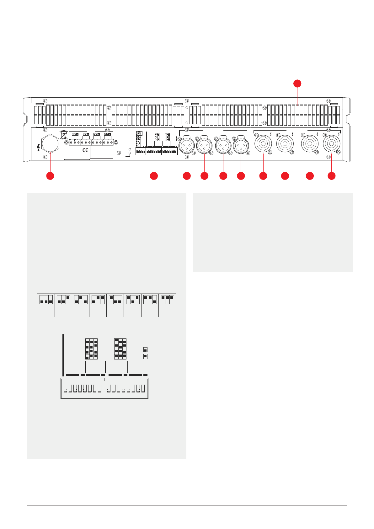
REAR PANEL
1 AC CORD
Plug this cord into the power supply socket.
(Before using the power amplifier, check if the power
supply is 220V).
2 VPL SELECTOR
CH D : the left number 123 is for power limit switch
CH C : the left number 456 is for power limit switch
CH B : the right number 123 is for power limit switch
CH A : the right number 456 is for power limit switch
3-6 CHANNEL D - CHANNEL A XLR INPUT
This XLR input is a balanced input. Connect this input to
the left output of your mixer.
7-10 CHANNEL D - CHANNEL A TURN LOCK OUTPUT
This SpeakOn 4 pin Outputs. Connect this turn lock output to
a speaker.
11 AIR EXIT
This part is the air exit. Don't obstruct it.
SPEAKER OUTPUTSBALANCED INPUTS
PUSH
CH D
A+B ON
1 2 3 4 5 1 2 3 4 5 6 7 8 1 2 3 4 5 6 7 8
ON ON
44dB
41dB
38dB
35dB
32dB
29dB
26dB
23dB
150V
121V
101V
83V
70V
56V
47V
38V
BRIDGE LED
220V-240V~50-60Hz
CH ACH BCH C LINE
CH D
C+D
PUSH
CH C
PUSH
CH B
PUSH
CH A CH D
1+CH D+
1-CH D-
XLR PIN 1-SCRN PIN 2-POS PIN 3-NEG
1+CH B+
1-CH B-
1+CH C+
1-CH C-
1+CH A+
1-CH A-
2+CH B+
2-CH B-
2+CH D+
2-CH D-
BRIDGE
1+: +
2-: -
CH C+D CH B CH A+B
BRIDGE C+D
BRIDGE A+B
VPL-VOLTAGE PEAK LIMITER
CH D
VPL
MODE
VPL VPL VPL
CH C CH B CH A
MODE
SWITCH
SOFT
HARD
MODE
MODE
MODE
1 2 3 4 5
GAIN
2 3 4 5 6 7 8 9 10
11
1
150V
1500W
121V
920W
101V
640W
83V
430W
70V
310W
56V
196W
47V
138W
38V
90W
FLEXIBLE OUTPUT POWER CHANGE (EACH CHANNEL)
PARAMETER TABLE.
1 2 3 4 5 6 7 8 1 2 3 4 5 6 7 8
ON ON
150V
121V
101V
83V
70V
56V
47V
38V
VPL-VOLTAGE PEAK LIMITER
CH D
VPL
MODE
VPL VPL VPL
CH C CH B CH A
MODE
SWITCH
SOFT
HARD
MODE
MODE
MODE
In this mode, connect the 4 inputs CH A and CH D to your
mixer's outputs. Put the selector on the stereo position. Output
volume can be adjusted by means of the two potentiometers.
Connect the 4 turn lock outputs to the 4 speakers.

5USER MANAUL
TECHNICAL SPECIFICATION
VL-20000Q DIMENSIONS
88mm
530mm
483mm
483mm
530mm
Number of Amplifier channels
Peak total output
Peak output voltage per channels
Max output current per channels
Max output power
Max output power bridged
4
10400W
150V
17.5A
4Ω 2600W / 8Ω 1500W
8Ω 1500W
SPECIFICATIONS
THD+N(1kHz) 1/4 Full power @8Ω
Slew Rate
Signal to noise ratio
Input impedance
<0.1%
30V/μs
>95dB
20kΩ Balance / 10kΩ Unbalance
150, 121, 101, 83, 70, 56, 47, 38V
300, 242, 202, 166, 140, 112, 94, 76V
Hard / Soft
23, 26, 29, 32, 35, 38, 41, 44dB
PERFORMANCE
VPL, selectable per channel
VPL, when bridged
Voltage peak limiter mode(Per channel)
Amplifier gain selectable(All channels)
GAIN, SENSITIVITY AND LIMITERS
Operating voltage, 230V
Minimum power-up voltage, 230V
Power average limiter(PAL)
Soft-start / Inrush current draw
Mains connector
130-265V
171V
Yes
Yes / Max. 5 A
230 V CE: 16A
POWER
Input connectors(Per channel)
Output connectors(Per channel)
Output bridge mode
Intelligent fans(On/Off)
Cooling
3-pin XLR
SpeakOn
A+B, C+D - Ch.’s A and C are Input Source
Yes, Depending on Presence of Output Signal
Dual Fan, Front to Rear Airflow
CONNECTORS AND BUTTONS
Height
Width
Depth
Weight
88mm (2U)
483mm
530mm
14.3kg
SIZE
AChannel
-10dB
0-inf
BChannel
-10dB
0-inf
CChannel
-10dB
0-inf
DChannel
-10dB
0-inf
SIG -20 -15 -10 -4 VPL CPL
SIG -20 -15 -10 -4 VPL CPL
VHF
PWR
PAL
TEM
MUTE
CLIP
HI-IMP
BRIDGE A+B
CLIP
HI-IMP
VHF
TEM
SIG -20 -15 -10 -4 VPL CPL
SIG -20 -15 -10 -4 VPL CPL
VHF
TEM
MUTE
CLIP
HI-IMP
BRIDGE C+D
CLIP
HI-IMP
VHF
TEM
NOMAD
LINK
Table of contents
Other VL Audio Amplifier manuals


