VMB TE-063 Instruction Manual

V.08.19
OPERATING INSTRUCTIONS USER MANUAL
MANUAL DE INSTRUCCIONES
TE-063
TOWERLIFT
TORRE ELEVADORA
ENES DE
TRAVERSENLIFT
BEDIENUNGSANLEITUNG
T
TORR
EN
DE
TRA

LIFTING TOWER TL-063
TORRE ELEVADORA TL-063
TRAVERSENLIFT TL-063
PRO LIFTS S.L.
C/ Ciudad de Barcelona Nº19
Pol.Ind. Fuente del Jarro
46988 Paterna (Valencia)
Tlf Export: +34 96 171 81 86
Tlf Nacional: 96 171 81 83
Manufacturer - Fabricante
Este manual de usuario y catálogo anexo de piezas de repuesto es propiedad de PRO LIFTS S.L.
Queda prohibida su reproducción total o parcial por cualquier medio que la tecnología actual permita.
Deposito legal y copyright 2014. Todos los derechos reservados.
MADE IN SPAIN (EU)
BGV-C1
BGG-912
EC Conformity Declaration pursuant to the EC Machinery Directives 89/392/CE and
98/37/CE: Manual lifters
)LQGDFRS\RIWKHFHUWL¿FDWLRQVDWWKHHQGRIWKLVERRNOHW
3XHGHYHUXQDFRSLDGHODVFHUWL¿FDFLRQHVDO¿QDOGHOPDQXDO
CONTENTS / ÍNDICE
Features of the TL-063 towerlift / Características TL-063....................3 - 4
English Quick operation guide....................................................................5 - 11
Manual de usuario Español.......................................................................... 12 - 19
Bedienungsanleitung Deutsch....................................................................20 - 26
Sketches / Planos piezas................................................................................ 27 - 34
Spare part list / Lista de repuestos..............................................................35 - 37

Depósito legal y copyright. Todos los derechos reservados. 3PRO LIFTS S.L.
F: )RUNV%UD]RVGHFDUJD
S: Transport compartment / Alojamiento de transporte
T: Transport wheels / Ruedas de transporte
V: :RUNLQJFRPSDUWPHQW$ORMDPLHQWRGHWUDEDMR
TL-063
S
F
V
S
T

Depósito legal y copyright. Todos los derechos reservados. 4PRO LIFTS S.L.
H: Handle / Manivela
L: Spirit level
N: )RUFHRQKDQGFUDQN)XHU]DVREUHPDQLYHOD
P: Leg / Pata
Q: Stabilizer / Estabilizador
R: Catch pawl / Gatillo bloqueo patas
SRS: Sequence Retainer System
W: Winch / Cabrestante
TL-063
L
P
H
QR
W
N1
N2
ALS-1
ALS-2
ALS-3
ALS-4
SRS

Depósito legal y copyright. Todos los derechos reservados. 5PRO LIFTS S.L.
4XLFNRSHUDWLRQJXLGH ENGLISH
CONTENTS
1. Introduction.
2. Technical information.
3. Safety precautions.
4. Operation.
5. Maintenance.
6. Guarantee.
1. INTRODUCTION
Dear customer, in order to ensure a safe
and reliable operation of the TL-063
towerlift please follow the instructions in
WKLVERRNOHWFDUHIXOO\%HIRUHRSHUDWLQJWKH
lift, read the instructions completely and
please note the technical information con-
tained within this manual.
All VMB products undergo very rigorous
testing, under strict conditions and they
are monitored continuously during the ma-
nufacturing process.
In order to guarantee the lifts function and
safety, only original parts from the manu-
facturer must be used. If any parts other
than those of the manufacturer are used,
RUWKHSURGXFWLVPRGL¿HGLQDQ\ZD\WKH
user forfeits all warranty rights to claim.
VMB reserves the right to modify the pro-
GXFWVSHFL¿FDWLRQVZLWKRXWSULRUQRWLFH
The model type, production year and se-
rial number must be quoted in any queries
or orders for spare parts.
2. TECHNICAL INFORMATION
2.1 - TL-063 Towerlift.
2.2 - Designed to lift loads, such as trus-
sing and lighting systems, vertically, up to
different heights.
2.3 -0D[LPXPORDGNJOE
2.4 - Minimum load: 25 Kg (55 lb).
2.5 - Security :
ALS$XWRPDWLF/RFN6\VWHP
2.6 - Maximum height : 6.25 m (20.6’).
2.7 - Folded height : 1.65 m (5.4’).
2.8 - Transport surface:
0,5 x 0,6 x 1,65m (1.64 x 1.97 x 5.4’)
2.9 - Shipping dimension:
0,53 x 0,63 x 1.67m (1.74 x 2.07 x 5.5’)
2.10 -:RUNVXUIDFH
1.94 x 2.01 m (6.36’ x 6.6’).
2.11 - Unit weight : 150 Kg (308.7 lb).
2.12. - Load support:
6KRUWIRUNVFP
2.13 - Construction material : 6082-T6
alluminium for the main body, comprised
RI SUR¿OHV DQG D OLIWLQJ FDUULDJH %DVH
DQGOHJVDUHPDGHRIVWHHOSUR¿OHDFFRU-
ding to DIN 2394. Catches and pulleys of
ST-37 steel.
2.14 - Winch: 900 Kg Maximum load with
DXWRPDWLFEUDNH/RQJFUDQN
&HUWL¿FDWLRQ&(DQG*67h9

Depósito legal y copyright. Todos los derechos reservados. 6PRO LIFTS S.L.
4XLFNRSHUDWLRQJXLGH ENGLISH
3. SAFETY PRECAUTIONS.
2.15 - Cable : Steel DIN 3060. Quality 180
Kg/mm2twist resistant.
Cable diameter: Ø6 mm
2.16 - Adjustable stabilizing feet with rub-
ber non-slip supports.
2.17 - Safety catches to anchor the legs.
2.18 - Antirust protection, primed paint
with cured polyester dust cover. The tower
can be supplied with natural aluminium
¿QLVKRUEODFNYHUVLRQ%
2.19 - Spirit level to adjust the tower ver-
tically.
2.20 - Swivel wheels to transport the lift
when folded.
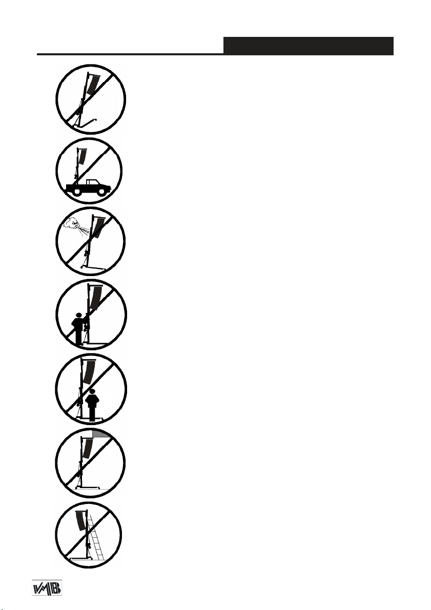
3.1 - The TL-063 is a machine designed to elevate
loads upwards in a vertical direction, It should NEVER
be used as a platform to elevate people.
3.3 - The maximum load indicated on the characteristics
label and the instructions manual should not be excee-
ded.
3.4 - This lift should NEVER be used to elevate a load
WKDWKDVQRWEHHQSURSHUO\FKHFNHG,WLVQHFHVVDU\WR
verify that the load is correctly supported and centred
on the appropriate lift support so that the weight of the
load will only elevate in a vertical direction.
3.2 - 2QO\SODFHWKHOLIWRQKDUGÀDWVXUIDFHVDOZD\V
FKHFNLQJWKDWLWLVLQDYHUWLFDOSRVLWLRQE\XVLQJWKHEXE-
ble level indicator (L) found on the base. Adjust the leg
stabilizers (Q) by turning the handles (H) to level if ne-
cessary. NEVER use wedges or other foreign objects to
balance the lift.

Depósito legal y copyright. Todos los derechos reservados. 7PRO LIFTS S.L.
4XLFNRSHUDWLRQJXLGH ENGLISH
3.6 - NEVER use the lift on a vehicle or any other mobile
surface.
3.7 - If there is a possibility of strong winds or gusts,
SODFHWKHOLIWRQWKHJURXQG¿UPO\DQGVHFXUHLWZLWKWKH
use of straps. NEVER attach a strap to a vehicle or any
other object that can possibly be moved.
3.8 - NEVER move the lift whilst it is carrying a load. It
is not advisable to carry out any type of horizontal mo-
vement even small positional adjustments.
3.9 - NEVER allow any team member below the load or
anybody else in the lifts operating zone.
3.10 - 7DNH FDUH ZLWK DOO REVWDFOHV DERYH WKH OLIW DQG
its extension zone such as cornices, balconies, and
luminous signboards. It is very important to avoid the
presence of all types of cables below the extended lift.
3.5 -&KHFNWKDWWKHOHJVP) are placed and set-up co-
rrectly with their safety pins (RLQVHUWHGDQGORFNHG
3.11 - Do not use stepladders on the lift or use it as a
support for them.

Depósito legal y copyright. Todos los derechos reservados. 8PRO LIFTS S.L.
4XLFNRSHUDWLRQJXLGH ENGLISH
3.12 -%HIRUHXVLQJWKHOLIWFKHFNWKHFRQGLWLRQRIWKH
FDEOH 7KH FDEOH VKRXOG QRW KDYH EURNHQ WKUHDGV RU
VKRZDQ\VLJQVRIFUXVKHGÀDWWHQHGDUHDV1(9(5XVH
faulty cables, always change them if there is any doubt.
Only use VMB steel cables; reference: DIN 3060.
Quality: 180KG/mm and torsion resistant.
3.14 - 'R QRW JUHDVH RU OXEULFDWH WKH ZLQFK¶V EUDNLQJ
PHFKDQLVP7KHEUDNHGLVNVKDYHEHHQJUHDVHGZLWK
a special heat and pressure resistant solution. Other
products should not be used to avoid negative effects
UHJDUGLQJWKHEUDNLQJPHFKDQLVP
3.15 - The minimum load to avoid problems regarding
WKHEUDNLQJPHFKDQLVPLV.J:LWKRXWWKLVORDGWKH
EUDNHZLOOQRWZRUN
3.16 -1(9(5WDNHDSDUWWKHFUDQNRIWKHZLQFKZKHQ
the lift is carrying a load or extended.
3.13 -$OOVHFWLRQVPXVWEHORZHUHG¿UVWDQGWKHOHJV
placed in its transport position, before transportation.
3.17 - Only original replacement parts should be used.
ORIGINAL

Depósito legal y copyright. Todos los derechos reservados. 9PRO LIFTS S.L.
4XLFNRSHUDWLRQJXLGH ENGLISH
4. USER INSTRUCTIONS.
4.1 - 3ODFHWKHOLIWRQD¿UPÀDWVXUIDFH
in the area it is to be used with the help of
the transport wheels (T).
4.2 -8QWLJKWHQWKHVHFXULW\NQREVK) and
remove the legs (P) from their transport
compartment (S) and fully insert them into
WKHLU ZRUNLQJ SRVLWLRQV V FKHFNLQJ WKDW
WKH\DUH¿[HGE\WKHSLQVR).
4.3 -&KHFNWKDWWKHOLIWLVLQYHUWLFDOSRVL-
tion using the spirit level (L) at the base of
the tower, adjust the stabilizer (Q), turning
the handle (H) if necesary.
4.4 -5HOHDVHWKHIRUNVF) and place them
LQ LWV ZRUNLQJ SRVLWLRQ UHDG\ WR WDNH WKH
ORDGRQWKHP,QVHUWWKHSLQVWREORFNWKH
IRUNV
4.5 - DO NOT OVERLOAD THE LIFT.
MAXIMUM LOAD IS 270 kg (595 lb) TL-063
The lift should NEVER be overloaded.
6DIHW\ DW ZRUN LV WKH PRVW LPSRUWDQW LV-
sue. Place the load onto the lift using an
adequate VMB support according to the
need, use so that the weight of the load
will only be elevated in a vertical direction.
The minimum load is 25 Kg.
4.6 - How to place the load:
Always load as close to the tower as
possible. The maximum load diminishes
according to the distance from the body
of the tower as illustrated in the diagram
4.6.1, which shows the load on the gravity
centre with distances to the lifting carriage
at a maximum lifting. Use a VMB adaptor
if necessary.
CAUTION
When two towers are used to elevate a
truss bridge, or many towers to elevate a
structure of any type, it is almost impossi-
ble that two or more people coordinate the
winches elevating or lowering the loads, at
exactly the same pace. At a certain point
each tower will be extended to different
height. For this reason it is necessary that
the structure does not stretch and allows
for these differences.
:LWKDULJLG¿[DWLRQDQGLIWKHOHYHOGLIIH-
UHQFH LV VLJQL¿FDQW WKH IRUFH JHQHUDWHG
from the handle of the winch will deform
the structure and apply a lateral force to
WKHOLIWVFDXVLQJWKHPWREUHDNDQGEORFN
WIND SPEED CALCULATIONS
7KH%*9&LVDQLQGRRUFHUWL¿FDWLRQ,I\RXDUHJRLQJWRXVHWKH
towerlift outdoor and require a wind speed calculation please con-
WDFWXVRUFRQWDFWDFHUWL¿HGVWUXFWXUDOHQJLQHHU

Depósito legal y copyright. Todos los derechos reservados. 10PRO LIFTS S.L.
4XLFNRSHUDWLRQJXLGH ENGLISH
Diagram 4.6.1
B
C
D
E
A
Distance from the
load’s center to the
lifting carriage
Maximum load
TL-063
A25 cm
(0.82’) NJOE
B30 cm
(0.98’) NJOE
C40 cm
(1.31’) NJOE
D50 cm
(1.64’) NJOE
For large forks:
E60 cm
(1.97’) NJOE
4.7 - Elevation:
7XUQWKHZLQFKFUDQNFORFNZLVHN1) to lift
WKH FDUULDJH DQG SUR¿OHV 7KH$/6 V\V-
tems enable the lift to rise and automati-
FDOO\EORFNWKHFDUULDJHDQGSUR¿OHVZKLOVW
rising ensuring that it will never fall. This
enables the cable to be without any force
and means it is only used for the elevation
and descent of the lift. The SRS (Sequen-
ce-Retainer-System) will also ensure that
WKHSUR¿OHVULVHLQVHTXHQFHRQHDIWHUWKH
other.
4.8 - Hold:
The tower can be left in any intermediate
position if it is necessary. Just stop turning
the handle of the winch and gently turn it
LQDQDQWLFORFNZLVHGLUHFWLRQN2WREORFN
WKH ODVW SUR¿OH ULVHQ 7KH $/6 ORFN ZLOO
WDNHWKHSUHVVXUHRIWKHORDGDQGUHOHDVH
strain applied on the cable.
4.9 - Lowering:
7R EULQJ WKH OLIW GRZQ \RX QHHG WR ¿UVW
WXUQ WKH ZLQFK KDQGOH VOLJKWO\ FORFNZLVH
(N1) and at the same time pull the red
$/6ORFN ALS-1) out. This releases the
EORFNLQJ V\VWHPV 7KHQ WXUQ WKH KDQGOH
DQWLFORFNZLVHN2), whilst maintaining the
$/6 ORFN SXOOHG RXW XQWLO WKH SUR¿OH KDV
been completely lowered. All red ALS
ORFNVALS-2, ALS-3 & ALS-C) should be
pulled out one by one whilst the handle is
WXUQHGDQWLFORFNZLVHN2DQGWKHSUR¿OHV
are brought down, one by one.
Security system ALS / ILS
The TL-063 incorporates the ALS securi-
W\V\VWHP$XWRPDWLF/RFN6HFXULW\7KLV
VMB red trigger system automatically
EORFNV WKH WRZHU LQ WKH SRVLWLRQ LW LV OHIW
in. Each section of the lift has an ALS that
EORFNVWKHVHFWLRQLQWKHXQOLNHO\HYHQWRI
WKHFDEOHEUHDNLQJ

Depósito legal y copyright. Todos los derechos reservados. 11PRO LIFTS S.L.
4XLFNRSHUDWLRQJXLGH ENGLISH
5.2 - The lift is supplied from the factory
completely greased. However, it is recom-
mended to periodically grease according
to use, the gearing, the axis bearings, the
VSLUDORIWKHFUDQNDQGWKHVHFWLRQV
5.3 - All lifts should undergo an annual te-
chnical inspection carried out by an autho-
UL]HG90%GHDOHUWRFKHFNWKHFHUWL¿FDWLRQV
and general condition of all the
lift’s elements and security systems invol-
ved in the lift’s use.
5.4 - Only use original spare parts to gua-
rantee a continued security level. The user
loses all rights to warranty if any spare
parts other than originals are used or ca-
UULHV RXW DQ\ PRGL¿FDWLRQ RU DOWHUDWLRQ WR
the towerlift.
5.5 - To request a spare part please indi-
cate the corresponding code which can be
found in this manual together with the lift’s
serial number and year of manufacture.
6. GUARANTEE.
The warranty period for this lift is 2 years
from the date of purchase.
PRO LIFTS S.L. promises, that from the
date of purchase and during the warranty
period to resolve any faults that may occur,
produced through defect material or fabri-
cation. Damage caused by improper use,
SURGXFWPRGL¿FDWLRQWKLUGSDUW\PDQLSXOD-
WLRQ RU DFFLGHQWDO ¿UH DUH QRW FRYHUHG E\
this warranty.
,I\RXUHOHDVH\RXU¿QJHUIURPWKH$/6ORFN
LW ZLOO DXWRPDWLFDOO\ EORFN ,Q WKLV FDVH UH-
SHDW WKH ¿UVW RSHUDWLRQ E\ WXUQLQJ VOLJKWO\
FORFNZLVHN1DQGWKHQDQWLFORFNZLVHN2)
ZKLOVWDOZD\VSXOOLQJWKHUHG$/6ORFNRXW,W
LVQHFHVVDU\WRFRPSOHWHO\ORZHUHDFKSUR¿-
le before starting to lower the next.
CAUTION:
THERE IS NO NEED TO PULL
THE ALS LOCKS HARD.
7KH\XQORFNZLWK WKHPLQLPXPSUHVVXUH,I
\RX¿QGLWGLI¿FXOWWRH[WUDFWSOHDVHWXUQWKH
ZLQFKFORFNZLVHVOLJKWO\VRWKDWWKHSLQLVQRW
holding all the weight, If you pull too hard
\RXFRXOGGDPDJHRUHYHQEUHDNWKH$/6
4.10 - Transport:
For the transport of the tower is necessary
WR IROG WKH PDFKLQH ORZHULQJ HYHU\ SUR¿OH
completely. Once the towerlift is completely
folded, place the legs in their transport com-
partment (S) and tighten the legs with the
VHFXULW\NQREVK), then the lift will be ready
to be transported.
5. MAINTENANCE.
5.1 - 5HJXODUO\ FKHFN WKH VWDWH RI WKH FD-
EOH,IWKHFDEOHKDVEURNHQWKUHDGVRULILW
VKRZVDQ\VLJQVRIFUXVKHGÀDWWHQHGDUHDV
it should be changed and replaced immedia-
tely with a new one. Do not use the lift if the
cables are in bad condition. Only use VMB
steel cables reference: DIN 3060 torsion re-
sistant.

Depósito legal y copyright. Todos los derechos reservados. 12PRO LIFTS S.L.
Manual de usuario ESPAÑOL
CONTENIDO
1. Introducción.
2. Información técnica.
3. Precauciones de seguridad.
4. Instrucciones de uso.
5. Mantenimiento.
6. Garantía.
1. INTRODUCCIÓN
EVWLPDGR FOLHQWH &RQ HO ¿Q GH JDUDQWL-
]DUXQIXQFLRQDPLHQWRVHJXUR\¿DEOHGH
la torre elevadora TL-063 por favor, siga
cuidadosamente las instrucciones de este
manual.
Antes de manipular la torre elevadora,
lea las instrucciones completas y tenga
en cuenta la información técnica conte-
nida en este manual. Todos los produc-
tos de VMB se someten a pruebas muy
rigurosas, en condiciones estrictas y son
monitorizados continuamente durante el
SURFHVRGHIDEULFDFLyQ&RQHO¿QGHJD-
rantizar el correcto funcionamiento y se-
guridad de los elevadores, sólo deben ser
utilizadas piezas originales del fabricante.
Si se utilizan piezas que no sean las origi-
nales del fabricante, o el producto se mo-
GL¿FDGHDOJXQDPDQHUDHOXVXDULRSLHUGH
todos los derechos de garantía.
90%VH UHVHUYD HOGHUHFKRGHPRGL¿FDU
ODVHVSHFL¿FDFLRQHV\ODVSLH]DVGHOSUR-
ducto sin previo aviso. El tipo de modelo,
año de producción y el número de serie
deben ser citadas en cualquier consulta o
pedido de piezas de recambio.
2. INFORMACIÓN TÉCNICA
2.1 - Torre elevadora TL-063.
2.2 - Diseñada para levantar estructuras,
trusses e iluminación en sentido vertical a
diferentes alturas.
2.3 -&DUJDPi[LPDNJOE
2.4 - Carga mínima: 25 Kg (55 lb).
2.5 - Seguridad: ALS(Sistema de gatillo
automático de seguridad).
2.6 - Altura máxima: 6.25 m (20.6’).
2.7 - Altura plegada: 1,65 m (5.4’).
2.8 - Dimensiones de la torre plegada:
0,5 x 0,6 x 1,65m (1.64 x 1.97 x 5.4’)
2.9 - Dimensiones de la caja transporte:
0,53 x 0,63 x 1.67m (1.74 x 2.07 x 5.5’)
2.10 - Área de la base:
1.94 x 2.01 m (6.36’ x 6.6’).
2.11 -3HVRGHODWRUUHNJOE
2.12 - Soporte de carga:
Brazos de carga cortos (54.5cm).
2.13 - Material de construcción: Cuerpo
principal de cinco tramos más carro ele-
YDGRU HQ SHU¿O GH DOXPLQLR H[WUXVLRQDGR
6082-T6. Base, patas y soportes varios,
HQ SHU¿OHULD GH DFHUR VHJ~Q ',1
Gatillos de seguridad y poleas acanala-
das en acero F-114.

Depósito legal y copyright. Todos los derechos reservados. 13PRO LIFTS S.L.
Manual de usuario ESPAÑOL
3. PRECAUCIONES DE SEGURIDAD
2.14 -&DEHVWUDQWHNJGHFDUJDPi[L-
ma con freno automático de retención de
ODFDUJD&HUWL¿FDFLyQ&(\*67h9
2.15 - Cable: Acero DIN 3060. Calidad de
UHVLVWHQFLDDODWRUVLyQNJPP2.
Diámetro del cable: Ø6 mm.
2.16 - Patas estabilizadoras ajustables
con soportes de goma antideslizante.
2.17 - Gatillos de seguirdad para anclar
las patas.
2.18 - Protección anti-óxido, imprimación
con pintura de polvo poliester al horno. La
torre puede ser suministrada con acaba-
do natural de aluminio o negro (versión
B).
2.19 - Nivel de burbuja para ajustar la ver-
ticalidad de la torre.
2.20 - Ruedas direccionales para el trans-
porte de la torre cuando este plegada.
3.1 - La torre elevadora TL-063 es una máquna diseñada
para la elevación de cargas en dirección vertical. NUNCA
se debe utilizar como plataforma eleavadora de personas.
3.3 - La carga máxima indicada en las características téc-
nicas mostradas en la etiqueta de la torre o en este manual
NO deben ser excedidas.
3.2 -&RORFDUHOHOHYDGRUVyORHQVXSHU¿FLHV¿UPHV\SODQDV
YHUL¿FDQGRTXHHVWiHQSRVLFLyQYHUWLFDOXWLOL]DQGRHOLQGL-
cador de nivel de burbuja (L) que se encuentra en la base.
Ajuste los estabilizadores (Q) girando las manivelas (H)
hasta nivelar, si es necesario. Nunca utilice cuñas u otros
objetos extraños para equilibrar el elevador.
3.4 - Este elevador NUNCA debe utilizarse para elevar una
carga que no ha sido correctamente revisada. Es necesario
YHUL¿FDUTXHODFDUJDHVWiFRUUHFWDPHQWHDSR\DGD\FHQWUD-
da en el soporte de elevación apropiado para que el peso de
la carga sólo actúe en una dirección vertical.
Depósito legal y copyright. Todos los derechos reservados. 14PRO LIFTS S.L.
Manual de usuario ESPAÑOL
3.6 - NUNCA use el elevador sobre un vehículo o cualquier
VXSHU¿FLHPyYLO
3.7 - Si existe la posibilidad de vientos fuertes o ráfagas,
FRORTXHHOHOHYDGRUHQHOVXHORFRQ¿UPH]D\¿MHORPHGLDQWH
WLUDQWHVWHQVRUHV1XQFD¿MHXQWLUDQWHDXQYHKtFXORRFXDO-
quier otro objeto que se pueda mover.
3.8 - NUNCA mueva el elevador mientras esté cargado. No
es aconsejable llevar a cabo cualquier tipo de movimiento
horizontal, ni tan sólo pequeños ajustes de posición.
3.9 - NUNCA permita que ningún miembro del equipo o
cualquier otra persona se sitúe debajo de la carga en la
zona de operación de las torres elevadoras.
3.5 - Comprobar que las patas (P) estén situadas correcta-
PHQWH\¿MDGDVFRQORVJDWLOORVGHVHJXULGDGR) los cuales
deben estar introducidos y bloqueados.
3.10 - Tenga cuidado con todos los obstáculos por encima
de la elevación y su zona de extensión, como cornisas, bal-
cones, letreros luminosos, etc. Es muy importante evitar la
presencia de todo tipo de cables por debajo de la torre ex-
tendida.
3.11 - No usar escaleras encima del elevador ni utilizarlo
como un apoyo para éstas.

Depósito legal y copyright. Todos los derechos reservados. 15PRO LIFTS S.L.
Manual de usuario ESPAÑOL
3.12 - Antes de utilizar el elevador, compruebe el estado
del cable. El cable no debe contener hilos rotos o mostrar
signos de áreas aplastadas/aplanadas.
NUNCA use cables defectuosos, siempre debe cambiarlos
si hay alguna duda. Utilice solamente cable de acero VMB
UHIHUHQFLD',1&DOLGDGNJPP\UHVLVWHQWHDOD
torsión.
3.13 - Antes de transportar la torre, todos los tramos deben
ser bajados, y las patas deben extraerse y colocarse en su
posición de transporte.
3.14 - No engrasar ni lubricar el mecanismo de freno del
cabestrante. Los discos de freno vienen engrasados con
una solución especial resistente a la presión y al calor. No
deben utilizarse otros productos, para evitar los efectos
negativos sobre el mecanismo de frenado.
3.15 - La carga mínima para evitar problemas relaciona-
GRVFRQHOPHFDQLVPRGHURWXUDHVNJ6LQHVWDFDUJD
mínima el freno no funcionará.
3.17 - Sólo deben ser utilizadas piezas de repuesto
originales de VMB PRO LIFTS S.L.
ORIGINAL
3.16 - NUNCA desmontar la manivela del cabrestante
cuando el elevador está soportando una carga o exten-
dido.

Depósito legal y copyright. Todos los derechos reservados. 16PRO LIFTS S.L.
Manual de usuario ESPAÑOL
4. INSTRUCCIONES DE USO.
4.1 - Coloque el elevador sobre una su-
SHU¿FLH¿UPH\SODQDGHOD]RQDGHWUDED-
jo sirviendose de las ruedas direccionales
de transporte (T).
4.2 -$ÀRMHORVSRPRVGHWUDQVSRUWHK) y
extraiga las patas (P) de su alojamiento
para transporte (S) e insertelas totalmen-
te en su posición de trabajo (V), compro-
bando que los gatillos de seguridad (R) se
LQVHUWDQ\¿MDQODSDWD
4.3 - Compruebe que la torre esta en
posición vertical sirviendose del nivel de
burbuja (LVLWXDGRHQHOSHU¿OEDVHVLHV
necesario ajuste la vertical de la torre con
los estabilizadores (Q) de las patas, giran-
do las manivelas (H).
4.4 - Libere los brazos de carga (F) y colo-
quelos en posición horizontal e inserte los
pasadores de seguridad.
4.5 - LA CARGA MÁXIMA PARA TL-063
ES 270 kg (595 lb).
El elevador NUNCA debe ser sobrecarga-
do. La Seguridad en el Trabajo es el ele-
mento más importante. Coloque la carga
en el elevador mediante un soporte ade-
cuado según la necesidad de modo que
el peso de la carga sólo actúe en direc-
FLyQYHUWLFDO/DFDUJDPtQLPDVRQNJ
4.6 - Como colocar la carga:
Cargue siempre tan cerca de la torre
como pueda. La capacidad de carga de
la torre decrece cuanto más lejos este la
carga separada de la torre, como se ilus-
tra en el esquema (4.6.1) de la siguiente
página. El cual muestra la carga en su
centro de gravedad con distancias al ca-
rro elevador que sostiene los brazos y a
máxima altura.
CALCULOS DE VELOCIDAD DE VIENTO
7HQJDHQFXHQWDTXHHOFHUWL¿FDGR%*9&HVSDUDPRQWDMHVHQLQWHULRUHV6LXV-
ted va a usar la torre al aire libre y requiere de un cálculo de velocidad de viento
puede ponerse en contacto con nosotros, o bien acudir a un ingeniero estructural
colegiado.

Depósito legal y copyright. Todos los derechos reservados. 17PRO LIFTS S.L.
Manual de usuario ESPAÑOL
B
C
D
E
A
necesario que la estructura no se esti-
re y permita estas diferencias. Con una
¿MDFLyQUtJLGD\VLODGLIHUHQFLDGHQLYHOHV
importante, la fuerza generada a partir de
la manivela del cabrestante deformará la
estructura y aplicará una fuerza lateral a
los elevadores provocando su bloqueo y
ruptura.
Sistema de seguridad ALS / ILS
El TL-063 incorporan el sistema de segu-
ridad patentado ALS (bloqueo automático
de seguridad). Este sistema VMB de gati-
llo rojo bloquea automáticamente la torre
en la posición que se deja. Cada tramo
de elevación tiene un ALS que bloquea
el tramo en el caso improbable de que el
cable se rompa. Para aún más seguridad
el carro también incorpora el sistema ILS
de bloqueo de inercia.
4.7 - Elevación:
Gire la manivela del cabestrante en sen-
tido horario (N1) para elevar el carro y los
tramos. El sistema de gatillos ALS le per-
mitirá elevar todos los tramos mientras
que estos se van bloqueando automáti-
camente, asegurando que la torre nunca
caerá. Esto hace que no actue ninguna
fuerza sobre el cable mientras la torre
HVWDSDUDGDORTXHVLJQL¿FDTXHVRORVHUi
usado para elevar y descender la torre.
El sistema único SRS permite que los
SHU¿OHVVHHOHYHQGHIRUPDVHFXHQFLDOX
ordenada, uno detrás de otro.
PRECAUCIÓN
Cuando se utilizan dos torres para elevar
un puente, descender truss o varias torres
para elevar una estructura de cualquier
tipo, es casi imposible que dos o más per-
sonas coordinen los cabrestantes exacta-
mente a la misma velocidad al elevar o
bajar las cargas. En un momento deter-
minado cada torre se elevará a una altura
diferente a la de las demás. Por ello, es
Esquema 4.6.1
Distancia del
centro de la carga
al carro elevador
Carga máxima
TL-063
A25 cm
(0.82’) NJOE
B30 cm
(0.98’) NJOE
C40 cm
(1.31’) NJOE
D50 cm
(1.64’) NJOE
For large forks:
E60 cm
(1.97’) NJOE

Depósito legal y copyright. Todos los derechos reservados. 18PRO LIFTS S.L.
Manual de usuario ESPAÑOL
los ALS rojos desbloqueados. Debe des-
cender completamente cada tramo antes
de empezar a bajar el siguiente.
CUIDADO:
NO HACE FALTA HACER FUERZA para
extraer los gatillos ALS, si nota que cues-
ta extraerlo, por favor gire la manivela del
cabrestante en sentido horario para que
el pasador del gatillo ALS no este aguan-
tando toda la presión. Si fuerza los gatillos
podría dañarlos o incluso romperlos.
4.7 - Transporte:
Para el transporte de la torre es necesa-
rio bajar completamente todos los tramos.
Una vez la torre haya sido plegada, co-
loque las patas en su alojamiento para
transporte (S) y apriete los pomos (K) de
presión, y la torre ya estará lista para su
transporte.
5. MANTENIMIENTO
5.1 - Comprobar periódicamente el esta-
do del cable. Si en el cable existen hilos
rotos, o si muestra signos de zonas aplas-
tadas/aplanadas, debe ser sustituido in-
mediatamente por uno nuevo. No use el
elevador si los cables están en mal esta-
do. Utilice solamente cable de acero DIN
3060 resistente a la torsión.
%ORTXHR
La torre puede dejarse en cualquier po-
sición intermedia si se requiere. Una vez
el sistema esta elevado hasta la altura
deseada tan solo deje de girar la mani-
vela y el freno automático del cabrestan-
te bloqueará y sujetará la carga, en este
momento gire la manivela del cabrestante
en sentido anti-horario (N2) para bloquear
el último tramo con el gatillo ALS rojo. Los
gatillos tomarán la presión de la carga y
liberará la tensión aplicada al cable.
4.9 - Descenso:
Para descender la torre es necesario,
primero girar la manivela del cabrestan-
te ligeramente en sentido horario (N1)
para liberar el gatillo ALS rojo (ALS-1), a
continuación girar la manivela en sentido
anti-horario (N2) mientras se sigue tirando
del gatillo ALS rojo (ALS-1), hasta que el
tramo esté completamente bajado. Todos
los gatillos ALS rojos (ALS-2, ALS-3 &
ALS-C) deben ser desbloqueados mien-
tras se gira la manivela del cabrestante
en sentido anti-horario (N2), repita esta
operación hasta descender todos los per-
¿OHVde uno en uno.
Si en el proceso se quita el mano del ALS
se bloqueará automáticamente. En este
caso, repita la primera operación girando
ligeramente la manivela en sentido hora-
rio, desbloquando el ALS y siguiendo en
sentido anti-horario, mantener al tiempo

Depósito legal y copyright. Todos los derechos reservados. 19PRO LIFTS S.L.
Manual de usuario ESPAÑOL
5.2 - La torre elevadora es suministrada
de fábrica completamente engrasada.
Sin embargo, se recomienda un engrase
periódico, según el uso, de las ruedas de
fricción, los cojinetes de eje, la espiral de
la manivela, y los tramos.
RECUERDE: NUNCA engrasar ni lubricar
el mecanismo de freno. No es necesario
engrasar los discos de freno. Los discos
de freno vienen engrasados con una so-
lución especial resistente a la presión y
al calor. No deben utilizarse otros produc-
tos, para evitar los efectos negativos so-
bre el mecanismo de frenado.
5.3 - Todos los elevadores se someten a
una inspección técnica anual llevada a
cabo por un distribuidor autorizado VMB
SDUD FRPSUREDU ODV FHUWL¿FDFLRQHV \ HO
estado general de todos los elementos de
elevación y sistemas de seguridad que in-
tervienen en el uso del elevador.
5.4 - Utilice únicamente piezas de repues-
to originales para garantizar el nivel de
seguridad de forma continuada. El usua-
rio pierde todos los derechos de garantía
si las piezas de repuesto utilizadas no son
originales o se utilizan o se lleva a cabo
FXDOTXLHUPRGL¿FDFLyQRDOWHUDFLyQGHOD
torre elevadora.
5.5 - Para solicitar una pieza de recam-
bio indique el código correspondiente que
se encuentra en este manual junto con el
número de serie de la torre y el año de
fabricación.
6. GARANTÍA
El período de garantía para este elevador
es de 2 años a partir de la fecha de com-
pra.
PRO LIFTS S.L. se compromete, que a
partir de la fecha de compra y durante el
período de garantía, a resolver los fallos
que puedan producirse, debidos a mate-
rial defectuoso o fabricación. Los daños
causados por un uso inadecuado, modi-
¿FDFLyQGHOSURGXFWRODPDQLSXODFLyQGH
terceros o incendio accidental no están
cubiertos por esta garantía.

Depósito legal y copyright. Todos los derechos reservados. 20PRO LIFTS S.L.
Bedienungsanleitung DEUTSCH
INHALTSVERZEICHNIS
1. Einführung.
2. Technische Daten.
3. Sicherheitsmaßnahmen.
4. Bedienungsanleitung.
5. Wartung.
6. Garantie.
=HUWL¿NDW
1. EINFÜHRUNG
Sehr geehrte Damen und Herren,
die vorliegende Betriebsanleitung wurde
PLWGHP=ZHFNHUVWHOOWHLQH]XYHUOlVVLJH
Bedienung des TL-063 Hebeturms zu
ermöglichen. Lesen Sie bitte die Betrie-
bsanleitung vor der Inbetriebnahme sor-
JIlOWLJGXUFK%LWWHEHDFKWHQ6LHDXFKGLH
technische Daten.
8QVHUH 3URGXNWH XQWHUOLHJHQ VWUHQJVWHQ
PrüfungenundKontrollenbeiderFertigung.
Es sind ausschließlich Original-Ersatzteile
zu verwenden. Für den Anwender werden
DOOH *HZlKUOHLVWXQJVDQVSUFKH DXIJH-
hoben, wenn er Nicht-Original-Ersatzeile
verwendet bzw. ÄQGHUXQJHQDP3URGXNW
selbst vormimmt.
2. TECHNISCHE DATEN.
2.1 - Hebeturm, Typ TL-063.
2.2 -'DV*HUlWLVW]XPVHQNUHFKWHQ+HEHQ
YRQ /DVWHQ ZLH %HOHXFKWXQJVN|USHU DXI
YHUVFKLHGH+|KHQNRQ]LSLHUWZRUGHQ
2.3 -=XOlVVLJH+XENUDIWNJOE
2.4 - Mindesthublast : 25 Kg.
2.5 -=XOlVVLJH+XEK|KHP
2.6 - Mindesthöhe: 1.65 m (5.4’)
2.7 - Gefaltete Dimensionen:
0,5 x 0,6 x 1,65m (1.64 x 1.97 x 5.4’)
2.8 - Abmessungen Box:
0,53 x 0,63 x 1.67m (1.74 x 2.07 x 5.5’)
2.9 -*UXQGSODWWHQÀlFKH
1.94 x 2.01 m (6.36’ x 6.6’).
2.10 -7UDQVSRUWJHZLFKWNJOE
2.11-:HUNVWRIIH$OXPLQLXP73UR¿O
%DVLVSODWWH XQG $XVOHJHU DXV 6WDKOSUR¿O
DIN 2349. Verschlüsse aus F-114 Stahl.
2.12 -([NOXVLYH$/66\VWHP
( Pat. Pen. 200501056)
2.13 -'LH:LQGHNJ
2.14 - Seildurchmesser: Steel DIN 3060.
4XDOLWlWNJPP2
Durchmesser: Ø6 mm
2.15 - Ausleger mit verstellbaren Spindeln
und rutschfesten Gummifüßen.
2.16 9HUDQNHUXQJ GHU $XVOHJHU EHU
Sicherheitsrastbolzen.
2.17 - Wasserwaage zum Einstellen der
VHQNUHFKWHQ7XUPODJH
2.18 - Korrosionsschutz und Veredelung
GXUFK HOHNWURO\WLVFKH &DGPLHUXQJ RGHU
9HUVLRQ % 6DWLQSRO\HVWHU (UKlOWOLFK LQ
Natur Aluminium oder.
2.19 - Transportrollen zum Bewegen des
7XUPVEHLVHQNUHFKWHUXQGHLQJHIDKUHQHU
StellungzurArbeitsstelle.(optionalTL–063)
Table of contents
Languages:
Other VMB Forklift manuals


