Voce DMI-64 Mark II User manual

DMI-64MARKIIUSER'SMANUAL
111 Tenth Street
Wood-Ridge, NJ 07075
(201) 939-0052

CONTENTS
Introduction...................................................................................................... ii
Section 1
USING THE DMI-64 MARK II
Unpacking the DMI-64 Mark II ................................................1-1
Front Panel..............................................................................1-2
Rear Panel ..............................................................................1-3
Setting Up...............................................................................1-4
MIDI Interface..........................................................................1-4
1/4-Inch Audio Outputs...........................................................1-5
9-Volt AC Connector...............................................................1-5
Powering up the DMI-64 Mark II..............................................1-6
Playing the DMI-64 Mark II......................................................1-6
Taking Care of the DMI-64 Mark II..........................................1-7
Section 2
PROGRAMMING THE DMI-64 MARK II
Editing Parameters..................................................................2-1
Parameter Information ............................................................2-3
Appendix A
FACTORY PRESETS TABLE
Appendix B
MIDI SYSTEM EXCLUSIVE INFORMATION
Appendix C
DMI-64 MARK II SPECIFICATIONS
Appendix D
CHANGING THE BATTERY IN THE DMI-64 MARK II
WARRANTY
ManualRev.3.2
DMI-64 Mark II User's Manual
i

INTRODUCTION
The DMI-64 Mark II is a digital synthesizer offering 64 dynamically assigned
voices. It is especially suited for reproducing classic keyboard sounds such as
those of tone-wheel and combo organs.
NOTE: For the remainder of this manual, the DMI-64 Mark II will be referred to as
the DMI-64 II.
The DMI-64 II comes with 99 factory preset programs. A program consists of
waveforms, effects selections, MIDI control map, and keyboard split settings.
The unit also includes 64 factory programed waveforms. These presets will
allow the user to begin playing the DMI-64 II right out of the box, without having
to do any programming. If necessary, any or all of the 99 preset programs may
be altered by using the built in Edit Mode or the "DMI-64 II Soft Control" software.
Eight of the 64 waveforms can be modified by the built in Edit Mode or the "DMI-
64 II Soft Control" software.
This manual consists of two sections:
Section 1: Basics of setting up, playing, and caring for your DMI-64 II.
Section 2: Detailed description of DMI-64 II programming.
ii

USING THE DMI-64 MARK II
Unpacking the DMI-64 II
Your DMI-64 II comes with the following items:
1. DMI-64 II User's Manual
2. External AC adaptor
3. MIDI Implementation Chart
4. Parameter Chart
5. Rubber Feet
NOTE: Save the DMI-64 II's packing carton. For carrying and shipping, it provides
the best protection short of a hard case.
DMI-64 Mark II User's Manual
1-1
DMI-64
POWER COM
MARK II
2
43 5
PARAMETER VALUE
PRESET
1
PRESET/PARAMETER VALUE
USING THE DMI-64 MARK II
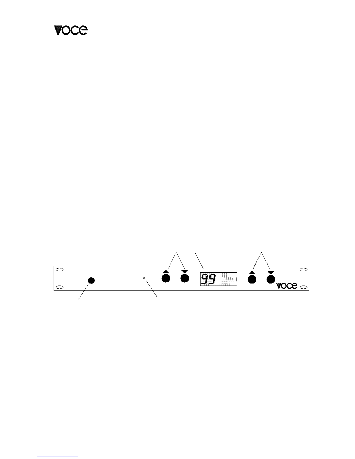
Front Panel
On the front of the DMI-64 II you will find the following:
1. POWER SWITCH - push on/push off
2. POWER/COMMUNICATIONS INDICATOR LED - This is a multipurpose
indicator. The indicator will light a green color when power is applied to the
unit, except when the unit is operating in EDIT MODE (refer to section 2 of
this manual for a description of EDIT MODE), in which case the indicator will
be red. When MIDI information is being transmitted (i.e. when you press or
release a key on a keyboard), the indicator will flash from GREEN to RED or
from RED to GREEN depending on whether you're in normal play mode or
EDIT MODE respectively.
3. Increment and Decrement buttons for changing preset or Edit Mode
parameter number.
4. Four digit LCD display - This is a multipurpose display used for the following
functions:
I - Display preset selection for the basic MIDI channel
II - Display programming parameters in EDIT MODE
5. Increment and Decrement buttons used only in Edit Mode to change a
parameter's value.
1-2
MIDI
THRU OUT IN
CH 1/MIX CH 2 9 VAC
20 WATTS
MADE IN USA
1
S/N
4
2
WOOD-RIDGE, NJ
voce inc
3
USING THE DMI-64 MARK II
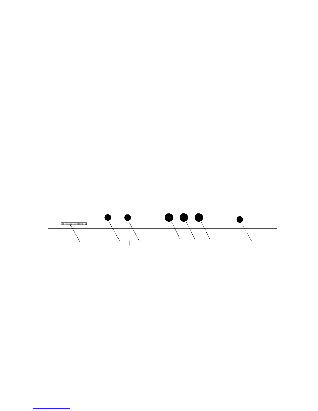
Rear Panel
On the rear panel of the DMI-64 II you will find the following:
1. This is your DMI-64 II's serial number.
2. 1/4 INCH UNBALANCED AUDIO CONNECTORS - These are 1/4 inch phone
jacks for connecting the DMI-64 II to an instrument amplifier.
3. MIDI IN / OUT / THRU DIN CONNECTORS - These are the connectors used
for connection to other MIDI devices. The DMI-64 II functions in accordance
with the IMA MIDI standard.
4. AC CONNECTOR - This connector is for supplying power to the DMI-64 II.
It mates to a matching connector on the AC adaptor provided with the unit.
DMI-64 Mark II User's Manual
1-3

USING THE DMI-64 MARK II
Setting Up
Remove the DMI-64 II and the AC adaptor from its carton being careful not to
damage the computer floppy disk.
MIDI Interface
The DMI-64 II uses the IMA MIDI protocol to communicate with a MIDI control-
ler. A MIDI controller can be a keyboard (The DMI-64 II has no keyboard of its
own), a sequencer or computer capable of sending MIDI information through a
MIDI output port.
To connect a MIDI controller to the DMI-64 II follow these three steps:
Step 1: Using a standard MIDI cable, connect one end of the cable to the MIDI
OUT port of your MIDI controller. Connect the other end of the cable
to the MIDI IN port of your DMI-64 II.
(Step 2 is optional)
Step 2: If you are using the MIDI controller with more than one MIDI instrument,
in your MIDI setup, you can use the DMI-64 II's MIDI THRU port to
connect to the next MIDI instrument. You can do this by connecting
one end of a MIDI cable to the MIDI THRU port on the DMI-64 II.
Connect the other end of the cable to the MIDI IN port of the next MIDI
instrument.
CAUTION: USEONLYADINCABLEWITH180oMALE5-PINDINCONNECTORS.
The MIDI OUT port on the DMI-64 II rear panel is used for MIDI system exclusive
communication to a computer. This feature may be used with the DMI-64 II Soft
Control program installed on a computer with MIDI IN and MIDI OUT ports, or
other patch librarians.
1-4

USING THE DMI-64 MARK II
1/4-Inch Audio Outputs
The 1/4 inch outputs provide CH1/MIX & CH2 audio outputs to your instrument
amplifier(s). Connect one end of a mono 1/4 inch cable to the CH1/MIX audio
output of the DMI-64 II. Connect the other end of the cable to the audio input
of your instrument amplifier or other audio equipment. Repeat this procedure
for the CH2 audio output if desired.
For a mono amplifier setup, use the CH1/MIX output. If no plug is inserted into
the CH2 connector, the CH1/MIX output will provide a signal which is the sum
of CH1 and CH2.
Several modes of audio assignment are possible with the DMI-64 II. A preset
may be setup to play on only Audio Channel 1, Audio Channel 2, on both (Mono),
or on both (Stereo). The former modes are useful when using a split program
or multitimbral mode. For example, a split program may have the preset active
below a certain MIDI note assigned to Audio Channel 1 while the upper preset
may be assigned to the other audio channel. The latter mode (Stereo) may be
used with the rotating speaker effect to provide a more "spacious" sound.
9-Volt AC Connector
The 9-Volt AC connector is used to provide power to your DMI-64 II.
You will notice two 6 ft. long cables on either side of the AC adaptor provided
with the DMI-64 II. One cable has a standard two pronged AC plug. The other
cable has a standard 2.5mm power connector which mates to the DMI-64 II AC
power jack.
DMI-64 Mark II User's Manual
1-5

USING THE DMI-64 MARK II
Powering up the DMI-64 II
Before applying power to the DMI-64 II make sure the audio level on your in -
strument amplifier, mixing console or sound re-enforcement equipment is
reduced to a minimum and that all the necessary connections have been
properly made as specified in section 2. The LED on the DMI-64 II should be
off indicating that power has not been applied. Power up the DMI-64 II by press-
ing the power switch. The LED should turn GREEN indicating that power has
been applied and that you are in normal play mode. You may see a RED flick-
er on the LED when power is first applied, this is normal. Also, on power up,
you will hear a slight "click", this comes from the audio protection relay in the
DMI-64 II. The DMI-64 II incorporates an audio protection relay to protect ex -
ternal audio equipment from surges during power up and power down.
Playing the DMI-64 II
For the following section we'll assume you have read and understood the sec-
tions on setting up and applying power to the DMI-64 II. Once the power has
been applied, slowly turn up the volume of your system and begin to play notes
on the keyboard. Be sure the MIDI controller is set to MIDI channel 1, as the
this is the factory default basic channel. As you press the keys on your keyboard
you will notice that the LED on the DMI-64 II begins to flash. This means that
the DMI-64 II is receiving MIDI information from your keyboard and that you
should be hearing audio. Adjust the volume to a comfortable level and begin to
play.
You may change the preset the DMI-64 II is sounding by using the leftmost In-
crement and Decrement buttons whennot in EDIT MODE. You will notice that
the two digits on the display represent the preset number in use on the basic
MIDI channel only. If you are using a multitimbral setup, the presets active on
other MIDI channels will not be displayed. Refer to section 2 for an explanation
of programming the DMI-64 II for multitimbral use. Refer to Appendix A for a
listing of the DMI-64 II's factory programed settings. This table lists the various
preset settings that come pre-programed in your DMI-64 II.
There are 11 MIDI control changes the DMI-64 II will respond to. A separate
controller map exists for each DMI-64 II preset. While most control changes
only serve to change the virtual switches supported by the DMI-64 II, a con -
tinuous controller may be assigned for channel volume. The following is a list
of virtual switch function supported by the DMI-64 II: Vibrato On, Chorus On,
Rotating Speaker On, Rate Select, Depth Select, Percussion On/Off, Percussion
Waveform Select, Percussion Decay Select, Percussion Volume Select, and Dis-
tortion On/Off.
You will need a MIDI implementation chart for your particular MIDI controller.
The MIDI implementation chart will aid in interfacing with your MIDI controller to
the DMI-64 II.
1-6

USING THE DMI-64 MARK II
Taking Care of the DMI-64 II
The DMI-64 II has been designed to meet the special needs of the professional
musician. Because of this, every attempt has been made to design a rugged
yet compact instrument which will perform reliably for years to come. But, like
any other musical instrument, we strongly recommend that you take the proper
precautions during normal use. In order to maintain the DMI-64 II in proper
working order, keep the following points in mind:
1. The DMI-64 II does not require adjustments of any kind, internal or external.
The only time it may be necessary to open up the unit is for replacement of
the 3 Volt Lithium Battery used for backing up the non-volatile preset
memory. The preset memory holds the DMI-64 II's patch settings and the
eight user programmable waveforms. This battery should provide up to 4
years of backup. Should it become necessary to replace the battery, see
your dealer or contact Voce Inc. for a replacement battery or for information
on where to obtain one.
The following is a list of replacement batteries:
Sanyo 2340 270 mA/Hr
Panasonic BR2330 250 mA/Hr
You may replace the battery by either bringing it to your dealer or you can
do it yourself. Replacing the battery is a simple operation requiring a Phillips
Head screw driver and about 15 minutes of your time (see Appendix D).
2. Keep the DMI-64 II away from direct sunlight or excessive heat or cold. Do
not expose to rain.
3. Do not throw, kick, drop, crush, or spill liquids on the DMI-64 II. Although
we have made every effort to make the DMI-64 II as rugged as possible, it
is not indestructible.
4. Although the DMI-64 II employs an audio protection relay for the 1/4 Audio
Outputs, it is advisable that you always turn down the audio level before
powering up or down.
DMI-64 Mark II User's Manual
1-7

PROGRAMMING THE DMI-64 MARK II
Editing Parameters
Edit Mode is a special programming mode which allows the parameters which
make up a preset to be changed. This mode is activated by pressing the two
right most Increment and Decrement buttons simultaneously. Upon pressing
the buttons you will note that the COM LED changes color (from green to red),
indicating that you are in Edit Mode. You will also note that the display will read
"0000".
The display will now function in a different manner. Instead of displaying the
preset number, the leftmost pair of digits represent the parameter number to be
edited. The rightmost digits represent the parameter's value. Using the leftmost
Increment and Decrement buttons will select different parameters to edit while
using the rightmost buttons will change the parameters value. MIDI Program
Changes are inhibited while in Edit Mode to protect the user from accidentally
editing the wrong preset.
Most of the parameters in the Edit Mode menu apply only to the preset selected
at the time Edit Mode is enabled. Some parameters are global and apply to all
the presets or general functions of the instrument. A full parameter explanation
will follow later in the manual.
The editable parameters fall into general categories: Waveform Select, Effects,
MIDI Controller Map, Pitch and Volume offsets, Audio Channel Assignment,
Channel Split, Waveform Generation, MIDI System Exclusive Dumps, and Mul-
titimbral Channel Selects.
There are 64 waveforms available for use in the DMI-64 II. The last 8 of these
waveforms (56 - 63) are programmable by the user. The method provided in
Edit Mode for creating waveforms is an additive one similar to using harmonic
drawbars on an organ. Any of the DMI-64 II waveforms, except the one being
edited, may be used as a base waveform of which harmonic copies of itself of
varying amplitudes are added together. It is possible to do these harmonic
manipulations remotely through the use of MIDI system exclusive data. Refer
to Appendix B.
The DMI-64 II may be used multitimbrally. Up to 16 MIDI channels may be used
simultaneously with the DMI-64 II. Assuming that each MIDI channel is using a
split preset, that translates to a possible 32 different presets with 32 different
volumes with 32 different pitch transpositions with various effects. To use the
multitimbral mode, set Omni Off, and enable additional MIDI channels by select-
ing presets for the MIDI Channels Preset #s (parameters 59 - 74).
Parameters 75 and 76 provide the user a method of introducing "flaws" into the
organ sound. Electrical key click noise level can be adjusted using parameter
75. A 60Hz hum can be added to a keyed note by adjusting parameter 76.
DMI-64 Mark II User's Manual
2-1

PROGRAMMING THE DMI-64 MARK II
Editing Parameters (cont.)
Tone wheel organ harmonic foldback may be simulated by assigning various
waveforms to the 7 keyboard zones outined in the desciption of parameters 77
- 82. This allows the user to create different timbres for different ranges of notes.
A sustain / hold function is availible on the DMI-64 II. This allow the user to hold
chords while playing other keyboard. Parameter 83 is used to selected the MIDI
control number for this function.
The user may re-initilize the DMI-64 II to the factory presets by using parameter
84. This will return the unit's memory to the state which it was shipped from the
factory.
2-2

PROGRAMMING THE DMI-64 MARK II
Parameter Information
00 Exit - return to normal play mode, activate by pressing the Value Increment
button.
01 Basic Channel- This is the only MIDI channel the instrument will respond to
in Omni Off mode. Changes to this parameter may change the preset you are
editing because you are editing the current preset selected for the basic chan-
nel. * Value Range ( 01 - 16 ) Actual Value: ( 1 - 16 )
02 Omni Mode- selects one of two MIDI modes OMNI ON (respond to all MIDI
channels) or OMNI OFF (respond only to basic channel or selected multitimbral
channels).
* Value Range ( 00 - 01 ) Actual Value: 00 = OMNI OFF, 01 = OMNI
ON
03 Waveform # (Zone 2) - selects the waveform used by the digital voice os-
cillators.
Value Range ( 00 - 63 ) Actual Value: ( 0 - 63 )
04 Distortion - activates analog distortion circuitry. This effect is global for the
entire audio output of the instrument; it is important to remember this when the
effect is used in multitimbral setups or split programs.
* Value Range ( 00 - 01 ) Actual Value: 00 = Overdrive Off, 01 = Over-
drive On
05 Volume - used to adjust volume of preset excluding percussion effect
volume. This is useful in balancing split programs or multitimbral setups.
Value Range ( 00 - 63 ) Actual Value: 00 = Softest, 63 = Loudest
06 Semitone Offset - pitch offset for preset in semitones.
Value Range ( 00 - 64 ) Actual Value: 00 = -32 Semitones, 32 = 0 Semi-
tones, 64 = +32 Semitones
07 Micro tonal Offset - fractional pitch offset.
Value Range ( 00 - 64 ) Actual Value: 00 = -1 Semitone, 32 = 0 Semi-
tone, 64 = +1 Semitone
DMI-64 Mark II User's Manual
2-3

PROGRAMMING THE DMI-64 MARK II
Parameter Information (cont.)
08 FM Effects Data - selects effects such as Chorus, Vibrato, or Rotating
Speaker and their states.
Value Range ( 00 - 15 ) Actual Value: See table below
Parameter 8 Value Effect Virtual Switch Data
00
01
02
03
04
05
06
07
08
09
10
11
12
13
14
15
Rotating Speaker Effect
No frequency mod. effect Depth Sw. Off Rate Sw. Off
Vibrato Effect
Chorus Effect
Depth Sw. Off
Depth Sw. Off Rate Sw. Off
Rate Sw. Off
Depth Sw. Off Rate Sw. Off
Rotating Speaker Effect
No frequency mod. effect Depth Sw. On Rate Sw. Off
Vibrato Effect
Chorus Effect
Depth Sw. On
Depth Sw. On Rate Sw. Off
Rate Sw. Off
Depth Sw. On Rate Sw. Off
Rotating Speaker Effect
No frequency mod. effect Depth Sw. Off Rate Sw. On
Vibrato Effect
Chorus Effect
Depth Sw. Off
Depth Sw. Off Rate Sw. On
Rate Sw. On
Depth Sw. Off Rate Sw. On
Rotating Speaker Effect
No frequency mod. effect Depth Sw. On Rate Sw. On
Vibrato Effect
Chorus Effect
Depth Sw. On
Depth Sw. On Rate Sw. On
Rate Sw. On
Depth Sw. On Rate Sw. On
2-4

PROGRAMMING THE DMI-64 MARK II
Parameter Information (cont.)
09 Percussion Effects Data - selects percussion effect setup.
Value Range ( 00 - 15 ) Actual Value: See table below
Parameter 9 Value Virtual Switch Data
00
01
02
03
04
05
06
07
08
09
10
11
12
13
14
15
Perc. Wave Sel Off-Percussion Off- Perc. Vol. Off- Perc. Decay Off
Percussion Off-
Percussion Off-
Percussion Off-
Percussion Off-
Percussion Off-
Percussion Off-
Percussion Off-
Percussion On-
Percussion On-
Percussion On-
Percussion On-
Percussion On-
Percussion On-
Percussion On-
Percussion On-
Perc. Decay On
Perc. Decay Off
Perc. Decay On
Perc. Decay Off
Perc. Decay On
Perc. Decay Off
Perc. Decay On
Perc. Decay Off
Perc. Decay On
Perc. Decay Off
Perc. Decay On
Perc. Decay Off
Perc. Decay On
Perc. Decay Off
Perc. Decay On
Perc. Vol. Off-
Perc. Vol. On-
Perc. Vol. On-
Perc. Vol. Off-
Perc. Vol. Off-
Perc. Vol. On-
Perc. Vol. On-
Perc. Vol. Off-
Perc. Vol. Off-
Perc. Vol. On-
Perc. Vol. On-
Perc. Vol. Off-
Perc. Vol. Off-
Perc. Vol. On-
Perc. Vol. On-
Perc. Wave Sel Off-
Perc. Wave Sel Off-
Perc. Wave Sel Off-
Perc. Wave Sel On-
Perc. Wave Sel On-
Perc. Wave Sel On-
Perc. Wave Sel On-
Perc. Wave Sel On-
Perc. Wave Sel On-
Perc. Wave Sel On-
Perc. Wave Sel On-
Perc. Wave Sel Off-
Perc. Wave Sel Off-
Perc. Wave Sel Off-
Perc. Wave Sel Off-
DMI-64 Mark II User's Manual
2-5

PROGRAMMING THE DMI-64 MARK II
Parameter Information (cont.)
10 FM Effects Mask - selects which control switch settings (if any) are to be
modified by the FM Effects Data upon preset selection.
Value Range ( 00 - 07 ) Actual Value: See table below
11 Percussion Effects Mask- selects which control switch settings (if any) are
to be modified by the Percussions Effects Data upon preset selection.
Value Range ( 00 - 15 ) Actual Value: See table below
Parameter 10 Value Virtual Switch Enables (En = Enabled, Ne = Not Enabled)
00 Effect change Not enabled Depth Sw. Ne Rate Sw. Ne
Effect change Enabled01
02
03
04
05
06
07
Effect change Not enabled
Effect change Enabled
Effect change Not enabled
Effect change Enabled
Effect change Not enabled
Effect change Enabled
Depth Sw. Ne
Depth Sw. En
Depth Sw. En
Depth Sw. Ne
Depth Sw. Ne
Depth Sw. En
Depth Sw. En
Rate Sw. Ne
Rate Sw. Ne
Rate Sw. Ne
Rate Sw. En
Rate Sw. En
Rate Sw. En
Rate Sw. En
Parameter 11 Value Virtual Switch Enables (En = Enabled, Ne = Not Enabled)
00
01
02
03
04
05
06
07
08
09
10
11
12
13
14
15
Perc. Wave Sel Ne-Percussion Ne- Perc. Vol. Ne- Perc. Decay Ne
Percussion Ne-
Percussion Ne-
Percussion Ne-
Percussion Ne-
Percussion Ne-
Percussion Ne-
Percussion Ne-
Percussion En-
Percussion En-
Percussion En-
Percussion En-
Percussion En-
Percussion En-
Percussion En-
Percussion En-
Perc. Decay EnPerc. Vol. Ne-
Perc. Vol. En-
Perc. Vol. En-
Perc. Wave Sel Ne-
Perc. Wave Sel Ne-
Perc. Wave Sel Ne-
Perc. Wave Sel En-
Perc. Wave Sel En-
Perc. Wave Sel En-
Perc. Wave Sel En-
Perc. Wave Sel Ne-
Perc. Wave Sel Ne-
Perc. Wave Sel Ne-
Perc. Wave Sel Ne-
Perc. Wave Sel En-
Perc. Wave Sel En-
Perc. Wave Sel En-
Perc. Wave Sel En-
Perc. Vol. Ne-
Perc. Vol. Ne-
Perc. Vol. En-
Perc. Vol. En-
Perc. Vol. Ne-
Perc. Vol. Ne-
Perc. Vol. En-
Perc. Vol. En-
Perc. Vol. Ne-
Perc. Vol. Ne-
Perc. Vol. En-
Perc. Vol. En-
Perc. Decay Ne
Perc. Decay En
Perc. Decay Ne
Perc. Decay En
Perc. Decay Ne
Perc. Decay En
Perc. Decay Ne
Perc. Decay En
Perc. Decay Ne
Perc. Decay En
Perc. Decay Ne
Perc. Decay En
Perc. Decay Ne
Perc. Decay En
2-6

PROGRAMMING THE DMI-64 MARK II
Parameter Information (cont.)
12 Rotating Speaker Deceleration- the time it takes for the Rotating Speaker
Effect to slow down when the Rate Select control switch has been deactivated.
Value Range ( 00 - 99 ) Actual Value: 00 = fastest, 99 = slowest
13 Rotating Speaker Acceleration- the time it takes for the Rotating Speaker
Effect to speed up when the Rate Select control switch has been activated.
Value Range ( 00 - 99 ) Actual Value: 00 = slowest, 99 = fastest
14 Rotating Speaker Slow Velocity- the rotation rate which occurs at the end
of the deceleration time.
Value Range ( 00 - 20 ) Actual Value: 00 = slowest, 20 = fastest
15 Rotating Speaker Fast Velocity- the rotation rate which occurs at the end
of the acceleration time.
Value Range ( 00 - 20 ) Actual Value: 00 = slowest, 20 = fastest
16 Vibrato Depth(control switch off) - amount of vibrato effect produced when
the Depth Select control switch is deactivated.
Value Range ( 00 - 03 ) Actual Value: 00 = most shallow, 03 = deepest
17 Vibrato Depth(control switch on) - amount of vibrato effect produced when
the control switch is activated.
Value Range ( 00 - 03 ) Actual Value: 00 = most shallow, 03 = deepest
18 Chorus Depth(control switch off) - amount of chorus effect produced when
the Depth Select control switch is deactivated.
Value Range ( 00 - 03 ) Actual Value: 00 = most shallow, 03 = deepest
19 Chorus Depth(control switch on) - amount of chorus effect produced when
the Depth Select control switch is activated.
Value Range ( 00 - 03 ) Actual Value: 00 = most shallow, 03 = deepest
20 Vibrato Rate(control switch off) - vibrato effect speed when the Rate Select
control switch is deactivated.
Value Range ( 00 - 20 ) Actual Value: 00 = slowest, 20 = fastest
21 Vibrato Rate(control switch on) - vibrato effect speed when the Rate Select
control switch is activated.
Value Range ( 00 - 20 ) Actual Value: 00 = slowest, 20 = fastest
DMI-64 Mark II User's Manual
2-7

PROGRAMMING THE DMI-64 MARK II
Parameter Information (cont.)
22 Chorus Rate(control switch off) - chorus effect speed when the Rate Select
control switch is deactivated.
Value Range ( 00 - 20 ) Actual Value: 00 = slowest, 20 = fastest
23 Chorus Rate(control switch on) - chorus effect speed when the Rate Select
control switch is activated.
Value Range ( 00 - 20 ) Actual Value: 00 = slowest, 20 = fastest
24 Percussion Waveform (control switch off) - selects the percussion
waveform to be used when the Percussion Waveform Select control switch is
deactivated.
Value Range ( 00 - 63 ) Actual Value: (0 - 63)
25 Percussion Waveform (control switch on) - selects the percussion
waveform to be used when the Percussion Waveform Select control switch is
activated.
Value Range ( 00 - 63 ) Actual Value: (0 - 63)
26 Percussion Volume (control switch off) - selects the percussion volume to
be used when the Percussion Volume Select control switch is deactivated.
Value Range ( 00 - 63 ) Actual Value: 00 = Softest, 63 = Loudest
27 Percussion Volume (control switch on) - selects the percussion volume to
be used when the Percussion Volume Select control switch is deactivated.
Value Range ( 00 - 63 ) Actual Value: 00 = Softest, 63 = Loudest
28 Percussion Decay (control switch off) - selects the percussion decay time
to be used when the Percussion Decay Select control switch is deactivated.
Value Range ( 01 - 05 ) Actual Value: 01 = longest, 05 = shortest
29 Percussion Decay (control switch on) - selects the percussion decay time
to be used when the Percussion Decay Select control switch is activated.
Value Range ( 01 - 05 ) Actual Value: 01 = longest, 05 = shortest
30 Audio Channel Assignment - selects 1 of 4 possible audio output modes.
Value Range ( 01 - 04 ) Actual Value: 01 = Audio Ch. 1, 02 = Audio
Ch. 2, 03 = Mono, 04 = Stereo
2-8

PROGRAMMING THE DMI-64 MARK II
Parameter Information (cont.)
31 Split Note- determines the MIDI note number at which the channel split point
will occur, below this note the alternate preset will be active.
Value Range ( 00 - 99 ) Actual Value: 00 = no split, ( 1 - 99 ) = MIDI
note #
32 Alternate Preset - preset to be active simultaneously when channel split
mode is in use.
Value Range ( 01 - 99 ) Actual Value: ( 1 - 99 )
33 Volume MIDI Control Switch # - MIDI controller assignment for MIDI
Volume Control.
Value Range ( 00 - 99 ) Actual Value: 99 = Channel Pressure, (0 - 98)
= MIDI Control #
34 Rotating Speaker MIDI Control Switch #- MIDI controller assignment for
Rotating Speaker On control switch.
Value Range ( 00 - 99 ) Actual Value: 99 = Channel Pressure, (0 - 98)
= MIDI Control #
35 Vibrato MIDI Control Switch #- MIDI controller assignment for Vibrato On
control switch.
Value Range ( 00 - 99 ) Actual Value: 99 = Channel Pressure, (0 - 98)
= MIDI Control #
36 Chorus MIDI Control Switch #- MIDI controller assignment for Chorus On
control switch.
Value Range ( 00 - 99 ) Actual Value: 99 = Channel Pressure, (0 - 98)
= MIDI Control #
37 Depth MIDI Control Switch #- MIDI controller assignment for Depth Select
control switch.
Value Range ( 00 - 99 ) Actual Value: 99 = Channel Pressure, (0 - 98)
= MIDI Control #
38 Rate MIDI Control Switch # - MIDI controller assignment for Rate Select
control switch.
Value Range ( 00 - 99 ) Actual Value: 99 = Channel Pressure, (0 - 98)
= MIDI Control #
DMI-64 Mark II User's Manual
2-9

PROGRAMMING THE DMI-64 MARK II
Parameter Information (cont.)
39 Perc. On/Off MIDI Control Switch # - MIDI controller assignment for Per-
cussion On/Off control switch.
Value Range ( 00 - 99 ) Actual Value: 99 = Channel Pressure, (0 - 98)
= MIDI Control #
40 Perc. Decay MIDI Control Switch # - MIDI controller assignment for Per-
cussion Decay control switch.
Value Range ( 00 - 99 ) Actual Value: 99 = Channel Pressure, (0 - 98)
= MIDI Control #
41 Perc. Volume MIDI Control Switch #- MIDI controller assignment for Per-
cussion Volume Select control switch.
Value Range ( 00 - 99 ) Actual Value: 99 = Channel Pressure, (0 - 98)
= MIDI Control #
42 Perc. Waveform MIDI Control Switch # - MIDI controller assignment for
Percussion Waveform Select control switch.
Value Range ( 00 - 99 ) Actual Value: 99 = Channel Pressure, (0 - 98)
= MIDI Control #
43 Distortion MIDI Control Switch # - MIDI controller assignment for Distor-
tion On/Off control switch.
Value Range ( 00 - 99 ) Actual Value: 99 = Channel Pressure, (0 - 98)
= MIDI Control #
2-10
Table of contents
Other Voce Synthesizer manuals


