VoIP GW-522FW User manual

VoIP Wireless Router
User’s Manual
Version 1.0
(Feb. 2011)

Contents
1. Introduction........................................................................................................................................................4
1-1 Product Overview .......................................................................................................................................4
1-2 Hardware Description.................................................................................................................................5
2. VoIP Wireless Router Web Configuration........................................................................................................9
2-1 Status........................................................................................................................................................13
2-1-1 Current Status ................................................................................................................................13
2-1-2 RTP Packet Summary....................................................................................................................13
2-1-3 System Information........................................................................................................................14
2-1-4 Routing Table .................................................................................................................................15
2-1-5 LAN Client......................................................................................................................................15
2-2 FXS Line Diagnostics ...............................................................................................................................16
2-2-1 FXS Outward Test..........................................................................................................................16
2-2-2 FXS Inward Self Test......................................................................................................................17
2-3 General Settings.......................................................................................................................................18
2-3-1 WAN...............................................................................................................................................18
2-3-2 LAN ................................................................................................................................................22
2-3-3 SIP..................................................................................................................................................24
2-3-4 SIPAdvanced.................................................................................................................................29
2-3-5 Caller ID .........................................................................................................................................33
2-3-6 Hot Line..........................................................................................................................................34
2-3-7 Line settings...................................................................................................................................35
2-3-8 FAX.................................................................................................................................................39
2-3-9 Calling Features.............................................................................................................................41
2-3-10 Phone Book..................................................................................................................................43
2-3-11 CDR Settings................................................................................................................................44
2-4 Wireless Settings......................................................................................................................................45
2-4-1 Basic Settings ................................................................................................................................45
2-4-2 Advanced Settings .........................................................................................................................47
2-4-3 Security Settings............................................................................................................................47
2-4-4 Access Control ...............................................................................................................................50
2-4-5 WDS Settings.................................................................................................................................51
2-4-6 Site Survey.....................................................................................................................................53
2-4-7 WPS...............................................................................................................................................53
2-5 Advanced Settings....................................................................................................................................59
2-5-1 Codec setting .................................................................................................................................59
2-5-2 Digit Map........................................................................................................................................60
2-5-3 DTMF & PULSE.............................................................................................................................64
2-5-4 CPT / Cadence...............................................................................................................................65
2-5-5 Provision Settings ..........................................................................................................................66
2-5-6 Caller Filter.....................................................................................................................................68
2-5-7 Static Route....................................................................................................................................69
2-5-8 QoS Settigs....................................................................................................................................70
2-5-9 DDNS.............................................................................................................................................71
2-5-10 NAT Traversal...............................................................................................................................72
2-5-11 DoS Protection Settings...............................................................................................................73
2-5-12 DMZ / ALG....................................................................................................................................73
2-5-13 IP Filtering....................................................................................................................................74
2-5-14 Port Filtering.................................................................................................................................74
2-5-15 MAC Filtering ...............................................................................................................................75
2-5-16 Virtual Server................................................................................................................................75
2-5-17 Emergency No .............................................................................................................................76
2-5-18 UPnP............................................................................................................................................76

2-6 Tools.........................................................................................................................................................77
2-6-1 Ping Test.........................................................................................................................................77
2-6-2 STUN Inquiry..................................................................................................................................78
2-7 System Settings........................................................................................................................................79
2-7-1 NTP................................................................................................................................................79
2-7-2 Language .......................................................................................................................................80
2-7-3 Login Account.................................................................................................................................80
2-7-4 Backup / Restore............................................................................................................................81
2-7-5 System Log ....................................................................................................................................82
2-7-6 Save / Restart.................................................................................................................................82
2-7-7 Software Upgrade ..........................................................................................................................83
2-7-8 Logout ............................................................................................................................................83
3. Configuring the VoIP Router through IVR .....................................................................................................84
3-1 IVR (Interactive Voice Response) ............................................................................................................84
3-2 IP Configuration Settings..........................................................................................................................86
4. Dialing Principles.............................................................................................................................................88

VoIP Wireless Router User’s Manual 4
1. Introduction
1-1 Product Overview
The VoIP Router are designed to carry both voice and facsimile over the IP network. It uses the industry standard
SIP call control protocol so as to be compatible with free registration services or VoIP service providers’ systems.
As a standard user agent, it is compatible with all common Soft Switches and SIP proxy servers. While running
optional server software, the VoIP Router can be configured to establish a private VoIP network over the Internet
without a third-party SIP Proxy Server.
The VoIP Router can be seamlessly integrated into an existing network by connecting to a phone set and fax
machine. With only a broadband connection such as an ADSL bridge/router, a Cable Modem or a leased-line
router, the VoIP Router allows you to use voice and fax services over IP in order to reduce the cost of all long
distance calls.
The VoIP Router can be configured a fixed IP address or it can have one dynamically assigned by DHCP or
PPPoE. It adopts either the G.711, G.726, G.729A or G.723.1 voice compression format to save network
bandwidth while providing real-time, toll quality voice transmission and reception.

VoIP Wireless Router User’s Manual 5
1-2 Hardware Description
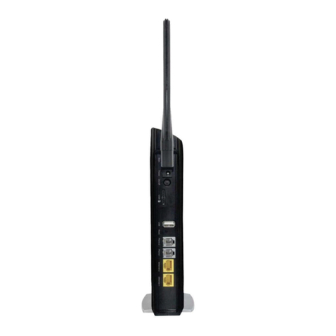
GW-522FW
Front Pannel
Indicators
Power: Power LED. A steady light indicates a proper connection to a power source.
Prov./Alm.: A blinking light indicates the VoIP Router can not register with SIP Server or can not get the IP
address. A blinking light also indicates the VoIP Router is attempting to connect with the Provisioning server.
Once the service connects, the LED will turn off. The LED will light solid red if the self-test or boot-up fails.
Reg.: The Register LED will turn on and continuously working when VoIP Router is connected to a VoIP
service provider. The LED will flash if not connected to a service provider.
WAN: When a connection is established the LED will light up solid. The LED will blink to indicate activity. If
the LED does not light up when a cable is connected, verify the cable connections and make sure your
devices are powered on.
WLAN: A steady light indicates a wireless connection. A blinking light indicates that the VoIP Router is
receiving/transmitting from/to the wireless network.
LAN: When a connection is established the LED (bottom) will light up solid on the appropriate port. The
LEDs will blink to indicate activity. If the LED does not light up when a cable is connected, verify the cable
connections and make sure your devices are powered on.
USB: This indicates that VoIP Router detects a supported 3G modem dungle or a USB device.
Phone: This LED displays the VoIP status and Hook/Ringing activity on the phone port that is used to
connect your normal telephone(s). If a phone connected to a phone port is off the hook or in use, this LED
will light solid. When a phone is ringing, the indicator will blink.
Line: Light on means the line is in use (off-hook).
WPS: Flashing in blue as wireless router processing WPS-PCB wireless connecting progress.

VoIP Wireless Router User’s Manual 6

VoIP Wireless Router User’s Manual 7
Rear Panel
1. WLAN Switch: Switch it to power on/off wireless feature.
2. Phone Port (1-2): Connect to your phones using standard phone cabling (RJ-11).
3. USB: Connect to a 3G USB dungle or a printer.
4. LAN: 10/100M fast Ethernet. Connect to your Ethernet enabled computers using Ethernet cabling.
5. Copper WAN: 10/100M fast Ethernet. Connect to your broadband modem using an Ethernet cable.
6. Optical WAN: Insert 100M fiber optic SFP module and connect to a switch or router.
Note: VoIP router allows alternative Copper or Optical WAN at the same time.
If you connect Copper WAN at first that Optical WAN will not take active unless remove RJ45 cable
from Copper WAN port.
If you connect Optical WAN at first that Copper WAN will not take active unless remove fiber from
Optical WAN port.
7. Ground: A conducting connection with the earth. Connect with the ground so as to make the earth a part of
an electrical circuit using metal wire.
8. Power Receptor: Receptor for the provided power adapter.
9. Power Switch: Press down to turn-on VoIP Wireless Router.
WARNING: DO NOT (1) connect the phone ports to each other (FXS to FXS) or (2) connect any
phone port directly to a PSTN line (FXS to PSTN) or to an internal PBX line (FXS to PBX extension).
(3) Stacking is forbidden. Doing so may damage your VoIP Router.

VoIP Wireless Router User’s Manual 8
WPS: WPS button for wireless WPS-PCB setup method.
Antenna: Connect to a wireless network.
Reset button: Use to restore factory default settings.
Use Reset Button to restore factory default settings:
1. Press and hold the reset button for 5 seconds.
2. As Alarm indicator is blinking, please release the reset button. Factory settings will be
restored.

VoIP Wireless Router User’s Manual 9
GW-532FW
Front Panel
Indicators
Power: Power LED. A steady light indicates a proper connection to a power source.
Prov./Alm.: A blinking light indicates the VoIP Router can not register with SIP Server or can not get the IP
address. A blinking light also indicates the VoIP Router is attempting to connect with the Provisioning server.
Once the service connects, the LED will turn off. The LED will light solid red if the self-test or boot-up fails.
Reg.: The Register LED will turn on and continuously working when VoIP Router is connected to a VoIP
service provider. The LED will flash if not connected to a service provider.
WAN: When a connection is established the LED will light up solid. The LED will blink to indicate activity. If
the LED does not light up when a cable is connected, verify the cable connections and make sure your
devices are powered on.
WLAN: A steady light indicates a wireless connection. A blinking light indicates that the VoIP Router is
receiving/transmitting from/to the wireless network.
LAN: When a connection is established the LED (bottom) will light up solid on the appropriate port. The
LEDs will blink to indicate activity. If the LED does not light up when a cable is connected, verify the cable
connections and make sure your devices are powered on.
USB: This indicates that VoIP Router detects a supported 3G modem dungle or a USB device.
Phone: This LED displays the VoIP status and Hook/Ringing activity on the phone port that is used to
connect your normal telephone(s). If a phone connected to a phone port is off the hook or in use, this LED
will light solid. When a phone is ringing, the indicator will blink.
WPS: Flashing in blue as wireless router processing WPS-PBC wireless connecting progress.

VoIP Wireless Router User’s Manual 10
Rear Panel
1. WLAN Switch: Switch it to power on/off wireless feature.
2. Phone Port (1-2): Connect to your phones using standard phone cabling (RJ-11).
3. USB: Connect to a 3G USB dungle or a printer
.
4. LAN: 10/100/1000M Gigabit Ethernet. Connect to your Ethernet enabled computers using Ethernet cabling.
5. Copper WAN: 10/100/1000M Gigabit Ethernet. Connect to your broadband modem using an Ethernet cable.
6. Optical WAN: Insert 100M/1000M fiber optic SFP module and connect to a switch or router.
Note: VoIP router allows alternative Copper or Optical WAN at the same time.
1. If you connect Copper WAN at first that Optical WAN will not take active unless remove
RJ45 cable from Copper WAN port.
2. If you connect Optical WAN at first that Copper WAN will not take active unless remove fiber
from Optical WAN port.
7. Ground: A conducting connection with the earth. Connect with the ground so as to make the earth a part of
an electrical circuit using metal wire.
8. Power Receptor: Receptor for the provided power adapter.
9. Power Switch: Press down to turn-on VoIP Wireless Router.
WARNING: DO NOT (1) connect the phone ports to each other (FXS to FXS) or (2) connect any
phone port directly to a PSTN line (FXS to PSTN) or to an internal PBX line (FXS to PBX extension).
(3) Stacking is forbidden. Doing so may damage your VoIP Router.

VoIP Wireless Router User’s Manual 11
WPS: WPS button for wireless WPS-PBC setup method.
Antenna: Connect to a wireless network.
Reset button: Use to restore factory default settings.
Use Reset Button to restore factory default settings:
1. Press and hold the reset button for 5 seconds.
2. As Alarm indicator is blinking, please release the reset button. Factory settings will be
restored.

VoIP Wireless Router User’s Manual 12
2. VoIP Wireless Router Web Configuration
The VoIP Router allows users to configure its settings using a web interface (Web UI). You can access the
Configuration Menu by opening a web-browser (e.g., Internet Explorer or Netscape Navigator) and entering the
factory default LAN IP address: 192.168.8.254.
Instructions
zOpen a Web-Browser (e.g., Explorer, Navigator, Opera, FireFox).
z Enter the LAN port IP address in the address filed and press Enter. The default LAN port IP address is:
192.168.8.254.
z The log-in screen below will appear after you connect. (The factory default settings for Username and
Password are left blank).
The VoIP Router does not allow multiple people to configure the VoIP Router simultaneously. Please
remember to logout or restart the system if you are not using the web configuration function.

VoIP Wireless Router User’s Manual 13
2-1 Status
2-1-1 Current Status
Status →Current Status
For Port Status, it includes if each port registers to Proxy successfully, the last dialed number, how many
calls each port has made since the VoIP Router is start, etc.
For Server Registration Status, it shows the registration status of DDNS, STUN and FXS Represent
Number.
2-1-2 RTP Packet Summary
Status →RTP Packet Summary
Display the information of the last call made. Press Refresh button to get the latest RTP Packet Summary.

VoIP Wireless Router User’s Manual 14
2-1-3 System Information
Status →System Information
For WAN Port Information, it shows IP address, subnet mask, default gateway and DNS server. If you use
PPPoE to obtain IP, you will know if the IP is obtained through this method. If IP address, subnet mask,
default gateway is blank, it means that the VoIP Router does not obtain IP.
For LAN Port Information, it shows LAN port IP, subnet mask, and the status of DHCP server.
For Hardware, it shows the hardware platform and driver version.

VoIP Wireless Router User’s Manual 15
2-1-4 Routing Table
Status →Routing Table
It displays routing table of VoIP Router.
2-1-5 LAN Client
The DHCP Clients table displayed LAN device that has already been assigned an address from VoIP
Router. You can check if the DHCP client has obtain an IP address.
Status →LAN Client

VoIP Wireless Router User’s Manual 16
2-2 FXS Line Diagnostics
2-2-1 FXS Outward Test
FXS Line Diagnostics ÆOutward Test
It allows operator to verify whether it is some problem on the cable between Phone Sets and VoIP Router.
Enable: Select the lines you want to test.
Enforced Test: Since the line test will interrupt a talking call, that VoIP Router will ignore the in used line. If
you would like to test all the lines you select even it is in used, please tick this item.
Test: Click start to test.
ACO: Clear alarm indication of the last test result.

VoIP Wireless Router User’s Manual 17
2-2-2 FXS Inward Self Test
FXS Line Diagnostics ÆInward Self Test
It allows operator to verify if it is some problem on the FXS chip set.
Enable: Select the lines you want to test.
Enforced Test: Since the line test will interrupt a talking call, that VoIP Router will ignore the in used line. If
you would like to test all the lines you select even it is in used, please tick this item.
Test: Click start to test.
ACO: Clear alarm indication of the last test result.

VoIP Wireless Router User’s Manual 18
2-3 General Settings
2-3-1 WAN
WAN (Wide Area Network) Settings are used to connect to your ISP (Internet Service Provider). The WAN
settings are provided to you by your ISP and oftentimes referred to as "public settings". Please select the
appropriate option for your specific ISP.
IP Configuration (Setting WAN Port)
There are five methods of obtaining a WAN port IP address:
1. DHCP, which means a Dynamic IP (Cable Modem)
2. Static IP
3. PPPoE (dial-up ADSL)
4. PPTP
Methods for using DHCP and PPPoE for obtaining an IP address may vary. If you are not familiar with
creating a network connection, please contact your local ISP.
After selecting the suitable option, click Accept at the bottom of the screen to save the settings.
You need to save the changes and restart the VoIP Router to make the changes active. Saving the settings:
Click MAINTENANCE and select Save/Restart in System from the left menu. Tick Save Settings and
Restart, then click Accept. Wait for about 50 seconds before the VoIP Router obtaining an IP address by
the method you selected.
Note: When the system has obtained a new IP address, and you are using a WAN port to enter the Web
Configuration Screen, the new IP address has to be used before you can get connected to the VoIP Router.
The same principle applies to the next two settings.
General Settings →WAN

VoIP Wireless Router User’s Manual 19
General Settings →WAN
DHCP: Select this option if your ISP (Internet Service Provider) provides you an IP address automatically.
Cable modem providers typically use dynamic assignment of IPAddress. The Host Name field is optional
but may be required by some Internet Service Providers.
General Settings →WAN
Static IP: Select this option if your ISP (Internet Service Provider) provides you a Static IP address. Enter
the IP address, Subnet Mask and Default Gateway IP.

VoIP Wireless Router User’s Manual 20
General Settings →WAN
PPPoE: Select this option if your ISP requires you to use a PPPoE (Point-to-Point Protocol over Ethernet)
connection. Enter the PPPoE Account, PPPoE Password and re-enter Password to confirm.
General Settings →WAN
PPTP: Point-to-Point Tunneling Protocol (PPTP) is a WAN connection. Enter the IP Address, Subnet
mask, PPTP Server, PPTP ID and Password.
This manual suits for next models
1
Table of contents
