3
THINGS YOU SHOULD KNOW
1.1 GAS APPLIANCE
Gas Safety (Installations and Use) Regulations. In
the interests of your safety and that of others it is a
legalrequirementthatallgasappliancesareinstalled
and correctly maintained by a competent person
and in accordance with the latest regulations.
1.2 ELECTRICAL SUPPLY
Pleaseensurethatthisappliancehasbeenproperly
connected to the electrical supply by means of a
doublepoleisolatororun-switchedsocket,andthat
thecorrectsize of fuse(3amp)has beenfitted(see
fig.2).
Warning: this appliance must be earthed!
1.3 GUARANTEE REGISTRATION CARD
Please take the time to fill out your guarantee
registration card. The completed warranty card
should be posted within 30 days of installation.
1.4
BENCHMARK
LOG BOOK
The
Benchmark
Log Book is supplied withyour
boiler. This important document must be
completedduringtheinstallation/commissioning
of your boiler. All CORGI Registered Installers
carry a CORGI ID card, and have a registration
number. Both should be recorded in your
Benchmark Log Book. You can check your
installerbycallingCORGIdirecton01256 372300.
Failuretoinstallandcommissiontheappliancein
accordance with the manufacturers instructions
mayinvalidate the warranty. This doesnotaffect
your statutory rights .
1.5 HOW DOES IT WORK?
Your AquaNova water heater is an instantaneous
gaswaterheaterthatoperatestoproducehotwater
whenever a hot water outlet (tap) is opened.
The AquaNova will operate whenever a flow of
water, through the appliance is sensed.
The AquaNova lights electronically and does not
have a pilot light. In the unlikely event of a fault
developingwithyourappliance,thesupplyofgasto
the burner will be terminated automatically.
1.8 DIMENSIONS
HEIGHT
WIDTH
DEPTH
640 mm
400 mm
246 mm
1.9 CLEARANCES REQUIRED
ABOVE
BELOW
SIDES
FRONT
150 mm
150 mm
50 mm
600 mm
1.6 DIAGNOSTIC FAULT INDICATOR
In the unlikely event of a fault developing, the
AquaNova displays a unique fault indicator that
helps identify where the fault lies.
1.7 LED STATUS INDICATOR
The AquaNova is equipped with 2 led status
indicators that gives a visual indication of whether
theapplianceisworkingnormally orhasdeveloped
a fault.
Fig. 2
GETTING STARTED
2.1 BEFORE SWITCHING ON
Beforeswitchingtheapplianceon,pleasefamiliarise
yourself with:
●how to isolate the appliance from the gas, water
and electricity supplies;
●the appliance controls.
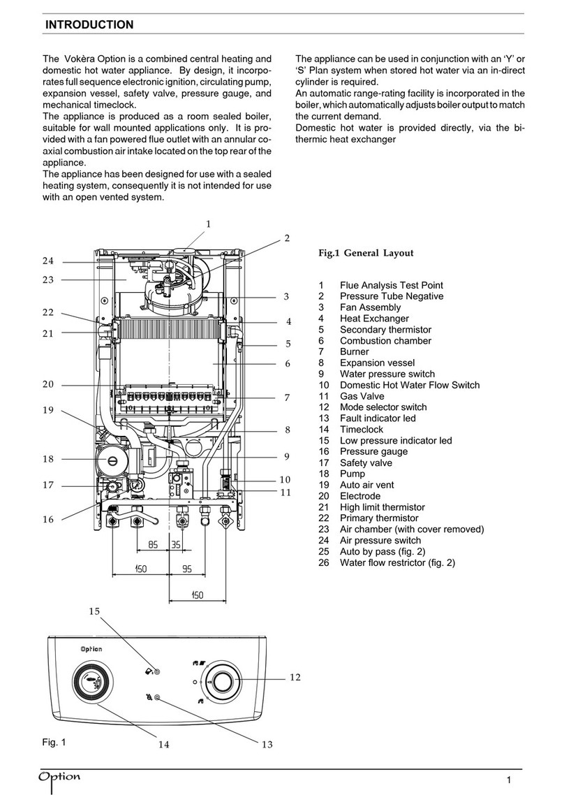
2.2 APPLIANCE CONTROLS (see fig. 1)
The appliance controls are situated on the front of
the appliance. The appliance has a mode switch,
variable thermostat. The mode switch has two
positions:
●OFF/RESET (0)
●ON (I)
The variable thermostat allows you to set the outlet
temperature between 40°C (min) and 65°C (max),
depending on the flow of water.
2.3 LIGHTING THE APPLIANCE
Ensurethegasandelectricalsupplytotheappliance
are switched on.
Turn the mode switch to the “I” (ON) position. The
status indicator should be “green” if the status
indicator is flashing “red” refer to 3.2.
Whenahotwateroutlet(tap)isopened,theappliance
will go through an ignition sequence, whereby the
burner will light.
If the appliance fails to ignite during the ignition
sequence, allow a period of two minutes before re-
setting.
To adjust the outlet temperature of the appliance
turn the thermostat knob clockwise to increase or
anti-clockwise to decrease.
When the appliance reaches the set temperature,
the burner will modulate to ensure temperature
stability.
Earth (Green/Yellow)
wire goes here
Neutral (Blue)
wire goes here Live (Brown)
wire goes here


