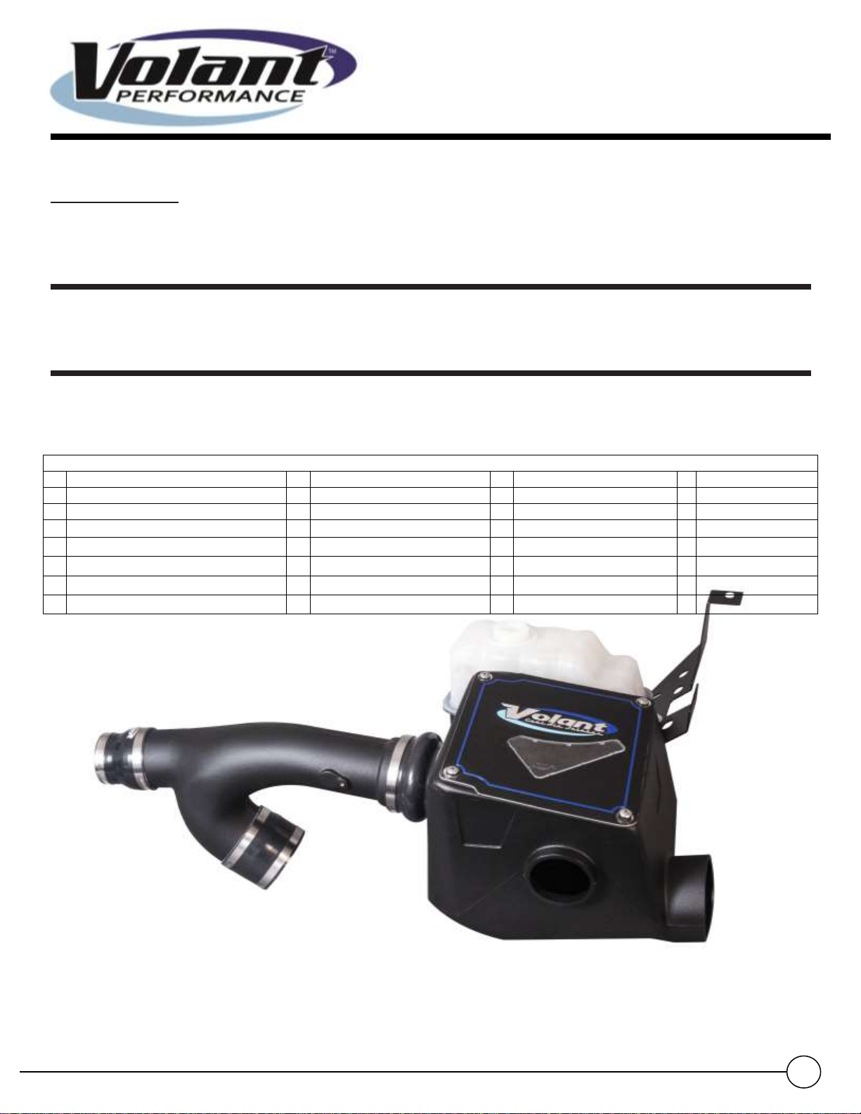
Closed Box Air Intake System
12-14 Ford F-150 3.5L
PN 19435/194356
Installation Instructions:
Locate your vehicle’s battery and disconnect the negative battery cable,
this resets the computer and clears old air flow data to prevent CEL errors.
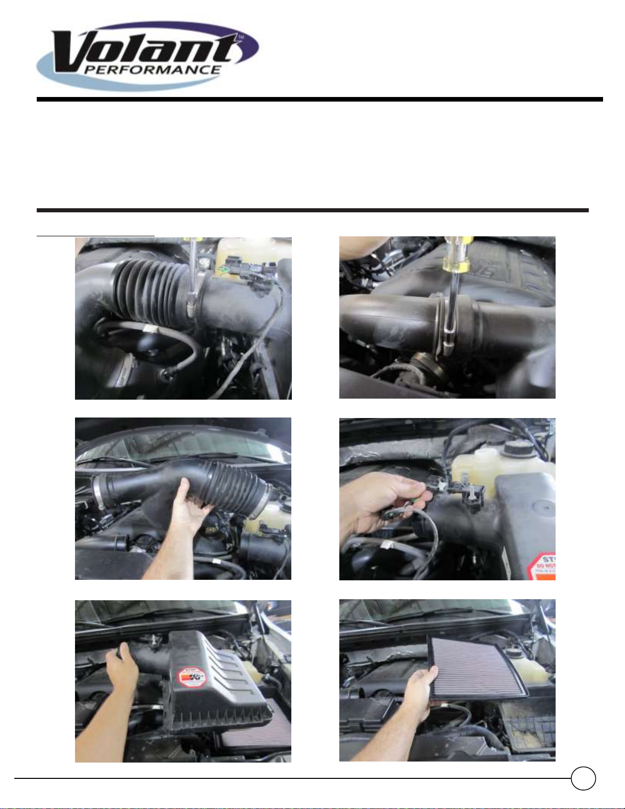
1. Using a 5/16 socket or nut driver loosen the clamp holding the factory air duct to the stock air box. (Fig A)
2. Using a 5/16 socket or nut driver loosen the clamps holding the factory air duct to the downpipes (Fig B)
3. Remove the air duct from the air box and downpipes by pulling straight off. Save in case vehicle needs to be
returned to stock. (Fig C)
4. Push out the red locking tab from the Mass Air Flow (MAF) harness then remove the harness from the sensor.
(Fig D)
5. Unclip the tabs holding the stock air box lid and remove the top of the stock air box. Save in case vehicle needs
to be returned to stock. (Fig E)
6. Remove the stock air filter. Save in case vehicle needs to be returned to stock. (Fig F)
7. Disconnect the hood sensor harness then remove bolt securing the sensor retention clip using a 10mm socket.
Save for re-installation. (Fig G)
8. Remove the 2 bolts holding the lower half of the stock air box in place. (Fig H)
9. Remove the 10mm bolt on the inner fender lip. Save for re-installation. (Fig I)
10. Lift up on the lower half of stock air box and coolant bottle. Position it so you can reach the three coolant lines
(Fig J)
WARNING: Over tightening hardware may alter the integrity of the Volant air intake system.
11. Install the stock bolt into the Volant coolant bottle mounting tray and hand tighten (Fig K)
12. Hand tighten the Volant tray onto the fender lip using the 10mm stock bolt from Step 9 . (Fig L)
13. Reinstall the hood sensor bracket in the stock location using the stock bolt from Step 7. (Fig M)
14. Route the hood sensor harness through the notch in the stock bracket and connect the harness to the sensor.
Tighten the tray using stock mounting bolts with hardware from Step 12. (Fig N)
15. Transfer the two small coolant lines onto the Volant bottle using the stock clamps. (Fig O)
16. Position the stock coolant bottle so the lower coolant hose can be removed without spilling the coolant. Remove
the C-clip holding the line in place. (Fig P)