CONTENTS
.
.
See
ti0
1
.
2
.
3
.
4
.
5
.
6
.
7
.
8
.
9
.
10
.
11
.
12
.
n
Ti
rle
Page
SPECIFICATIONS
.............................................
1
PERFORMANCE
..............................................
3
2-1 MaximumOutput
.........................................
3
2-2 Continuous RatedOutput
...................................
3
2-3 MaximumTorque and Fuel Consumption Ratio
at
MaximumOutput
.......
3
FEATURES
.................................................
5
GENERALDESCRIPTION
of
ENGINECONSTRUCTION
..................
5
4-
1
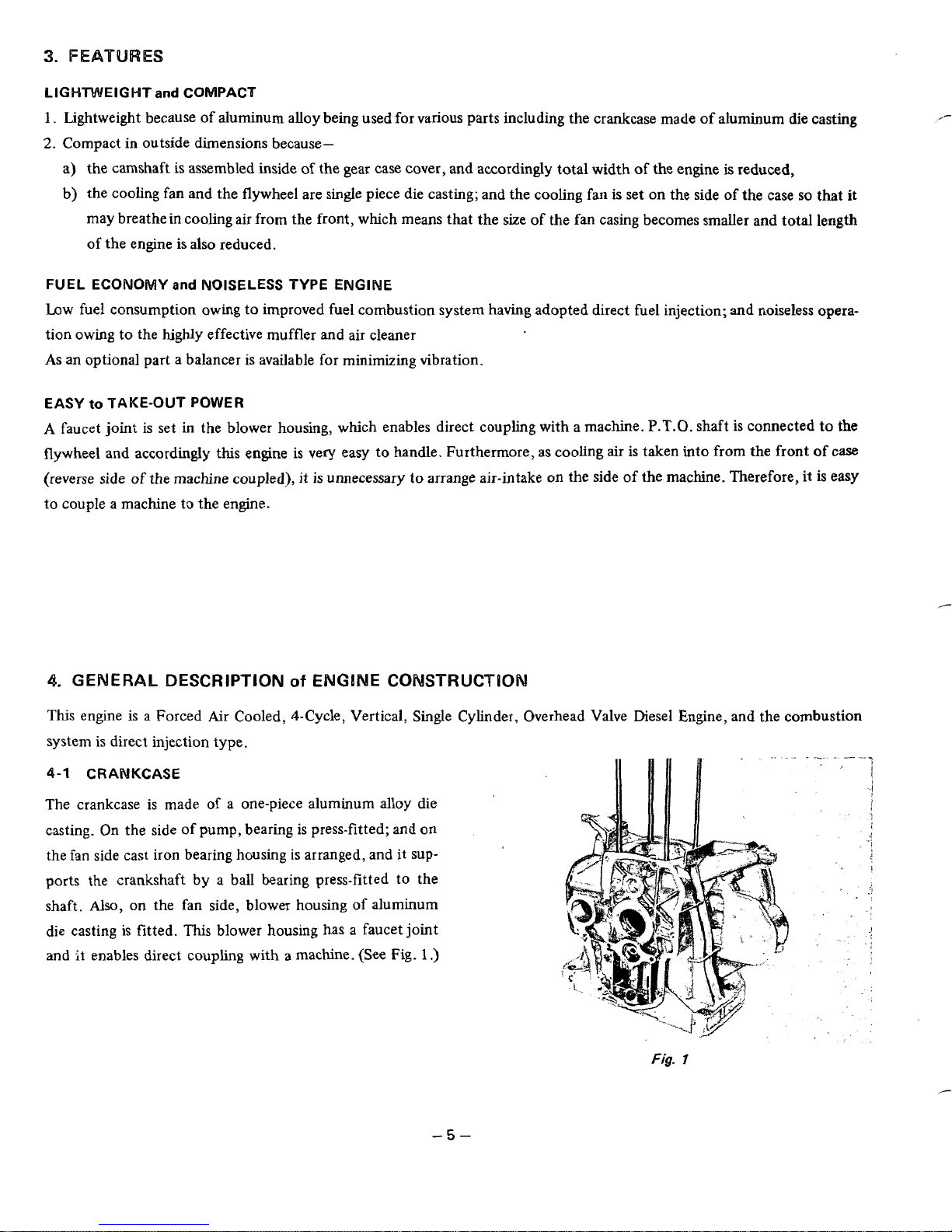
Crankcase
.............................................. 5
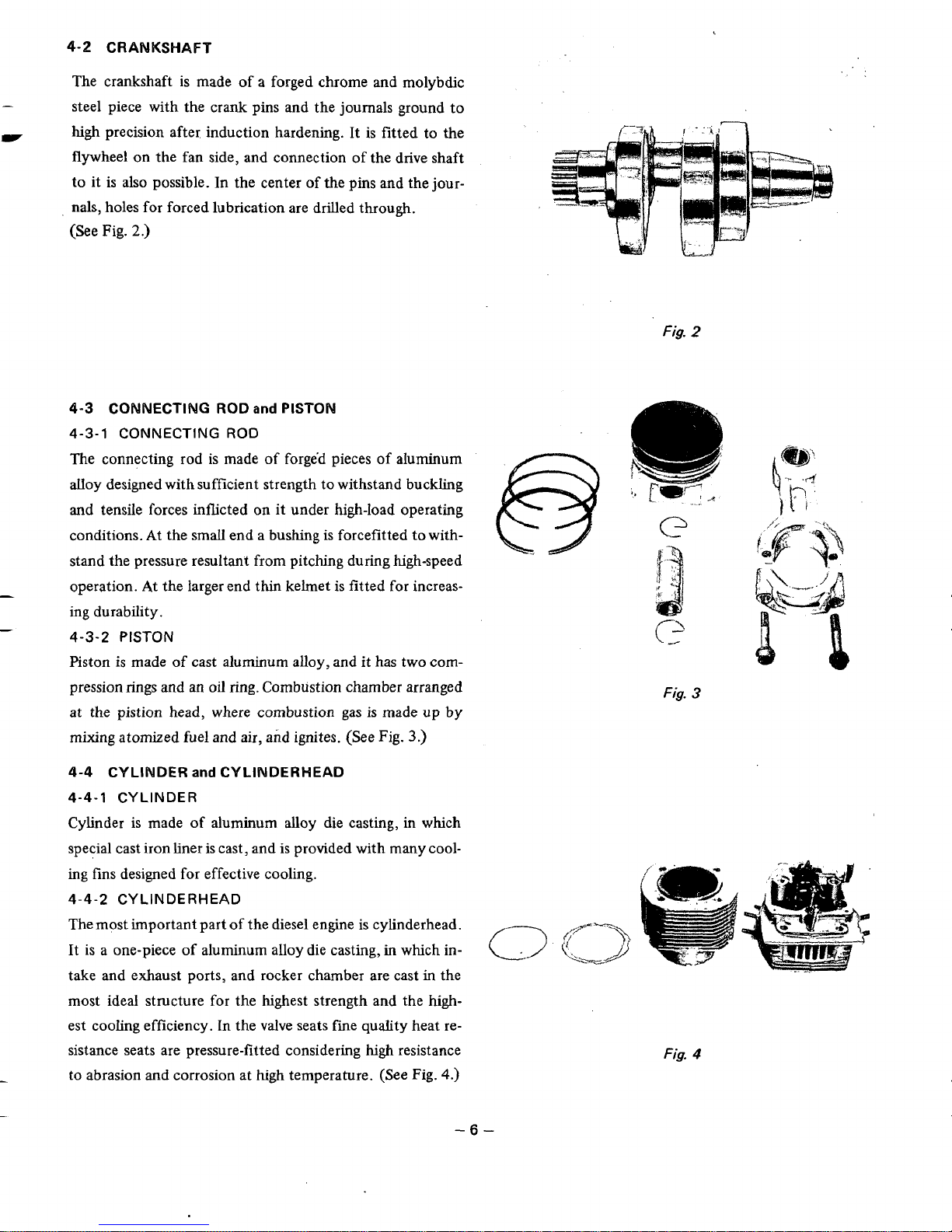
4-2 Crankshaft
.............................................
6
4-4 Cylinder andCylinderHead
..................................
6
4-5 GearCaseCover
..........................................
7
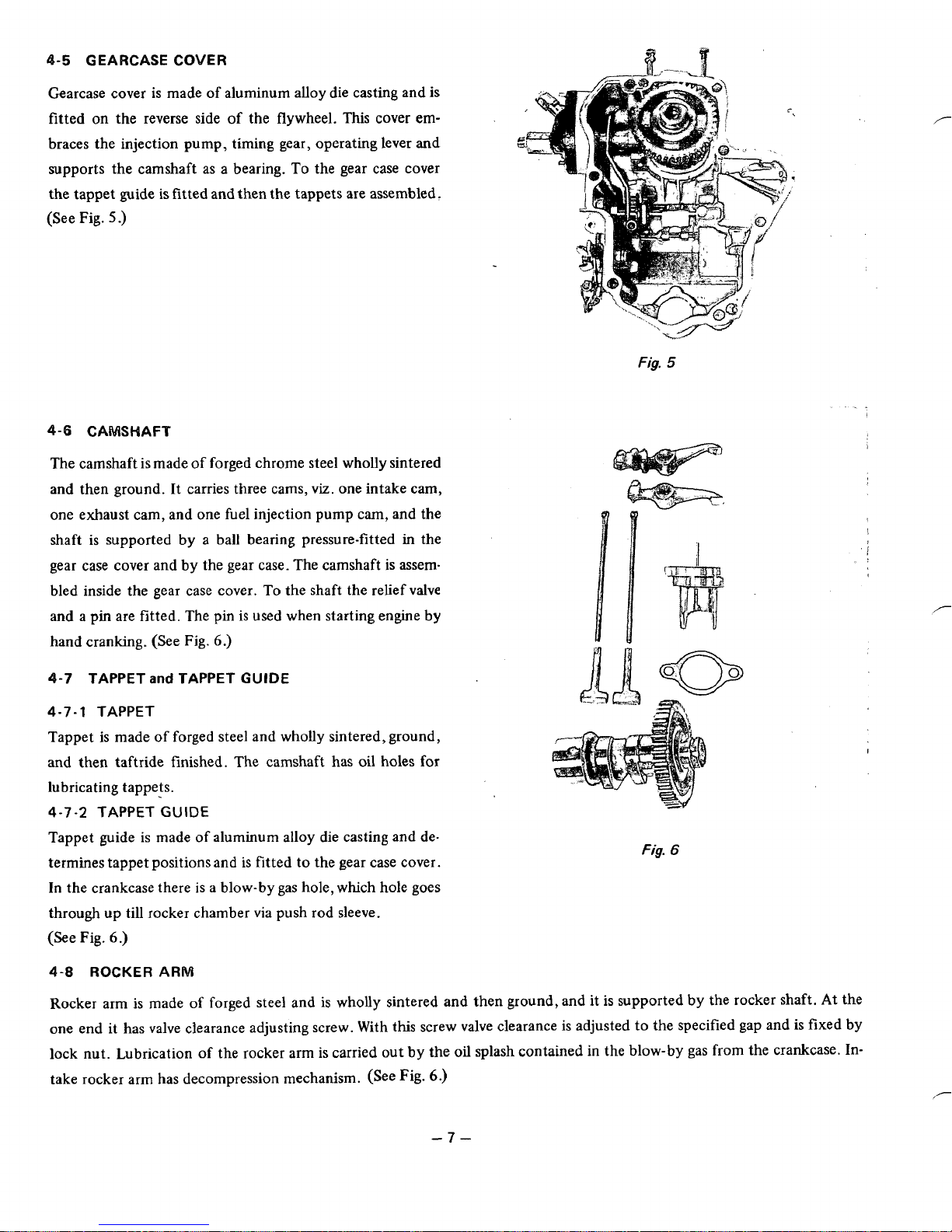
4-6 Camshaft
..............................................
7
4-8 Rocker Arm
............................................
7
4-9 Rocker Cover
............................................
8
4-10 GovernorSystem
.........................................
8
4-1
1
Lubrication System
........................................
8
4-13 Injection Pump
..........................................
9
4-14 Nozzle
................................................
9
4-
15 CombustionSystem
.......................................
10
4-16Sectional View of Engine
....................................
11
DISASSEMBLY
and
REASSEMBLY
.................
!
...............
13
5-2 Special
Tools
............................................
13
5-3 DisassemblySequence
......................................
14
5-4 How to Reassemble
........................................
20
FUEL
......................................................
28
6-1
Qualityof Fuel
..........................................
28
GENERALDESCRIPTION
of
AUXILIARYGADGETS
and
PARTS
...........
29
7
.
1 Fuel Injection
Pump
Mechanism
...............................
29
7-2
Fuel Injection Nozzle Holder
.................................
33
7-3 GovernorMechanismand Operation
.............................
36
7-4 Lubrication Systemand
Oil
Pump
..............................
38
7-5 OilFilter
...............................................
38
7-6 Electric Apparatus
........................................
39
INSTALLATION
..............................................
40
8-1 Installing
...............................................
40
8-2
Ventilation
.............................................
40
8-3 ExhaustGasDischarge
......................................
40
8-4
FuelSystem
............................................
40
8-5
PowerTransmission to DrivenMachines
..........................
40
CHECKS
and
CORRECTIONS
.....................................
41
TABLE
of
CORRECTIONSTANDARDS
..............................
42
MAINTENANCE
and
STORING
....................................
45
11
-1
Daily Checks andMaintenance
.................................
45
11
-2
Every
25
Hours Checksand Maintenance
.........................
45
11
-3
Every
50
Hours
(10
days)Checksand Maintenance
...................
45
11-4 Every
100
-
200 Hours (Monthly)Checksand Maintenance
.............
45
11
-5
Every
500
-
600 Hours(Semiannual) Checks
and
Maintenance
...........
46
11
-6
Every
1000
Hours (Yearly)Checksand Maintenance
..................
46
11
-7 Every
1500
Hours(Overhauls)
................................
46
11
-8 Preparationfor LongAbeyance
................................
46
REDUCTIONS
for
BTYPEENGINES
................................
47
12-1 Configuration
of
1/2 Reducer
................................
:
48
12-2 Structure
of
1/2 Reducer
....................................
49
12-3 DisassemblyandReassembly
of
1/2 Reducer
.......................
51
4-3 Connecting Rod andPiston
..................................
6
4-7 TappetandTappetGuide
....................................
7
4-12 CoolingSystem
..........................................
9
5-
1
PreparationsandSuggestions
.................................
13