Volantex ASW 28 User manual

instruction manual
...our glider...
This model is best suited for slope flying and aero tow, but will do well on a good thermal day. Due to its high aspect ratio, the ASW-28
will cover a lot of ground, but due to it's low wing loading, it has very smooth handling.
This medium sized 4m version of the ASW-28 can open up new soaring areas on slopes too small for large scale birds, but still give that
"Bigger is Better" feeling in the air.
...you will receive the...
The kit comes completely finished. The wings are finished and covered, spoilers installed and the ailerons are hinged, the
winglets are fiberglass molded. The clear plastic canopy is fitted to the fiberglass tray, wing joiner system is installed in the
fuselage. All what's required is your radio gear. You will need 4micro servos fro the ailerons and airbrakes, two regular
servo for the rudder and elevator.
WARRANTY
TOP modeltehnik ltd Model Manufacturing guarantees this kit to be free from defects in both material and workmanship at the date of purchase.
This warranty does not cover any component parts damaged by use, modification or tranposrt.
Further, TOP modeltehnik ltd reserves the right to change or modify this warranty without notice.
In that TOP modeltehnik ltd has no control over the final assembly or material used for final assembly, no liability shall be assumed nor
accepted for any damage resulting from the use by the user of the final user-assembled product. By the act of using the user-assembled
product, the user accepts all resulting liability.
If the buyer is not prepared to accept the liability associated with the use of this product, the buyer is advised to return this kit
immediately in new and unused condition to the place of purchase.
ARF
STYRO OBECHI wings
Wing Span:
Length:
Wing Area:
Wing Airfoil:
Loading:
Flying Weight:
RC functions:
4.0m
1.75m
76 dm2 HQ 3/15 - HQ
3/10
72 g/dm2
5.5 kg (88 oz)
elevator, ruder, ailerons,
airbrakes, retract

The ASW 28 is one of the best scale ships to learn on. If
you have never flown a glider, you will be surprised
how docile this glider is in the air. It is a real performer,
even on light lift. The two wingspans will allow you to
explore all the soaring capability, from smooth graceful
thermaling, to power lift with ripping high speeds and
adrenalin pumping aerobatics.
1. Your ASW 28 ARF should not be considered a toy,
but rather a sophisticated, working model that
functions very much like a full-size airplane. Because of
its performance capabilities, the ASW 28 ARF, if not
assembled and operated correctly, could possibly
cause injury to you or spectators and damage to
property.
2. You must assemble the model according to the
instructions. Do not alter or modify the model, as
doing so may result in an unsafe or unflyable model. In
a few cases the instructions may differ slightly from the
photos. In thoseinstances the written instructions
should be considered as correct.
3. You must take time to build straight, true and
strong.
4. You must use an R/C radio system that is in first-
class condition and components throughout the
building process.
5. You must correctly install all R/C and other
components so that the model operates correctly on
the ground and in the air.
6. You must check the operation of the model before
every flight to insure that all equipment is operating
and that the model has remained structurally sound.
Be sure to check clevises or other connectors often
and replace them if they show any signs of wear or
fatigue.
7. If you are not an experienced pilot or have not
flown this type of model before, we recommend that
you get the assistance of an experienced pilot in your
R/C club for your first flights. If you’re not a member of
a club, your local hobby shop has information about
clubs in your area whose
membership includes experienced pilots.
8. While this kit has been flight tested to exceed
normal use, if the plane will be used for extremely
high-stress flying, such as competition, the modeler is
responsible for taking steps to
reinforce the high-stress points and/or substituting
hardware more suitable for the increased stress.
9. WARNING: The fuselage and other parts included in
this kit is made of glass/carbon fiber, the fibers of
which may cause eye, skin and respiratory tract
irritation. Never blow into the fuselage to remove dust,
as the dust will blow back into your eyes.
Always wear safety goggles, a particle mask and
rubber gloves when grinding, drilling and sanding
carbon fiber parts. Vacuum the parts and the work
area thoroughly after working with carbon fiber parts.
We, as the kit manufacturer, provide you with a
top quality, thoroughly tested kit and instru-
ctions, but ultimately the quality and flyability
of your finished model depends on how you
build it; therefore, we cannot in any way
guarantee the performance of your completed
model, and no representations are expressed or
implied as to the performance or safety of your
completed model.
Remember:
Take your time and follow the instructions to
end up with a well-built model that is straight
and true.
The ASW 28 ARF requires a radio with a minimum of
four channels ( elevator, ailerons, rudder and
flaperon). The transmitter should have a throttle stick,
not a slider, especially when using
the flaperon (the stick allows for more precise throttle
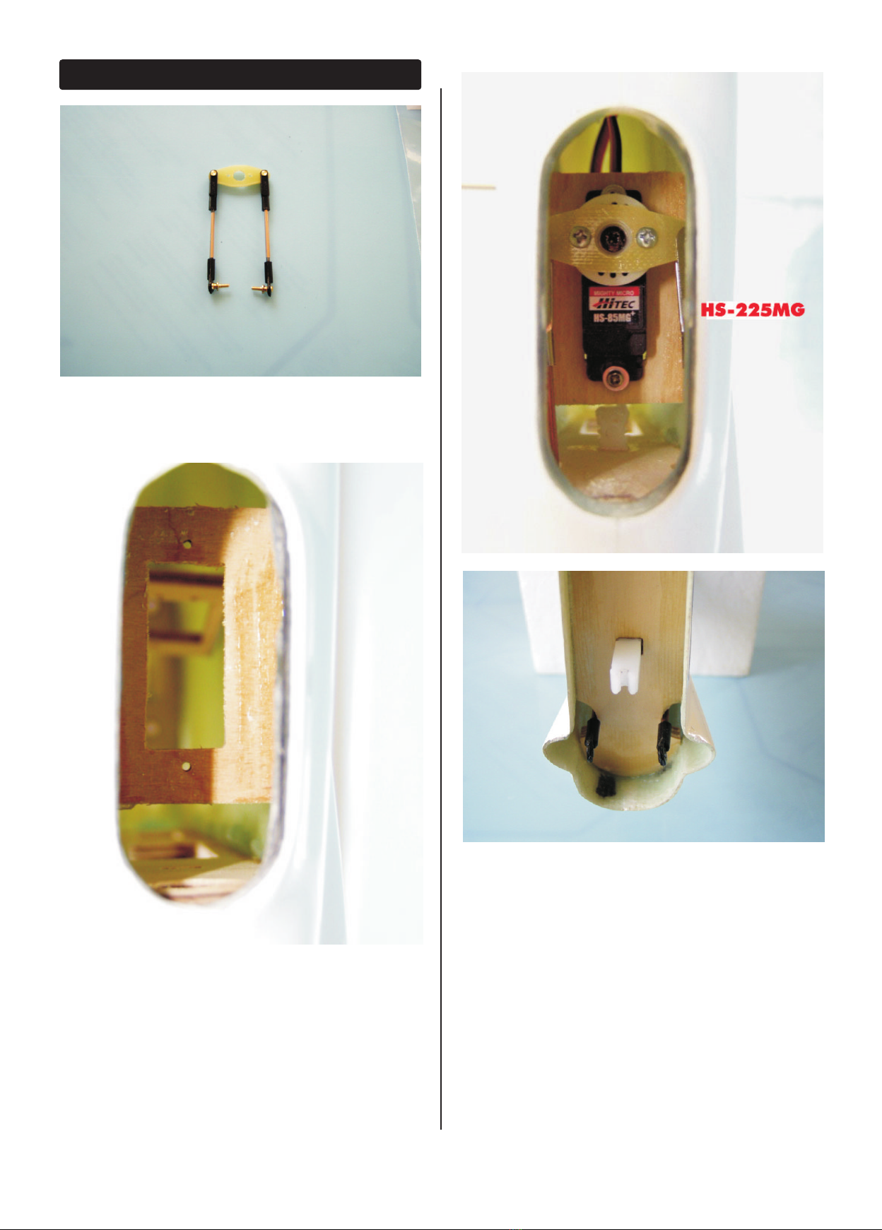
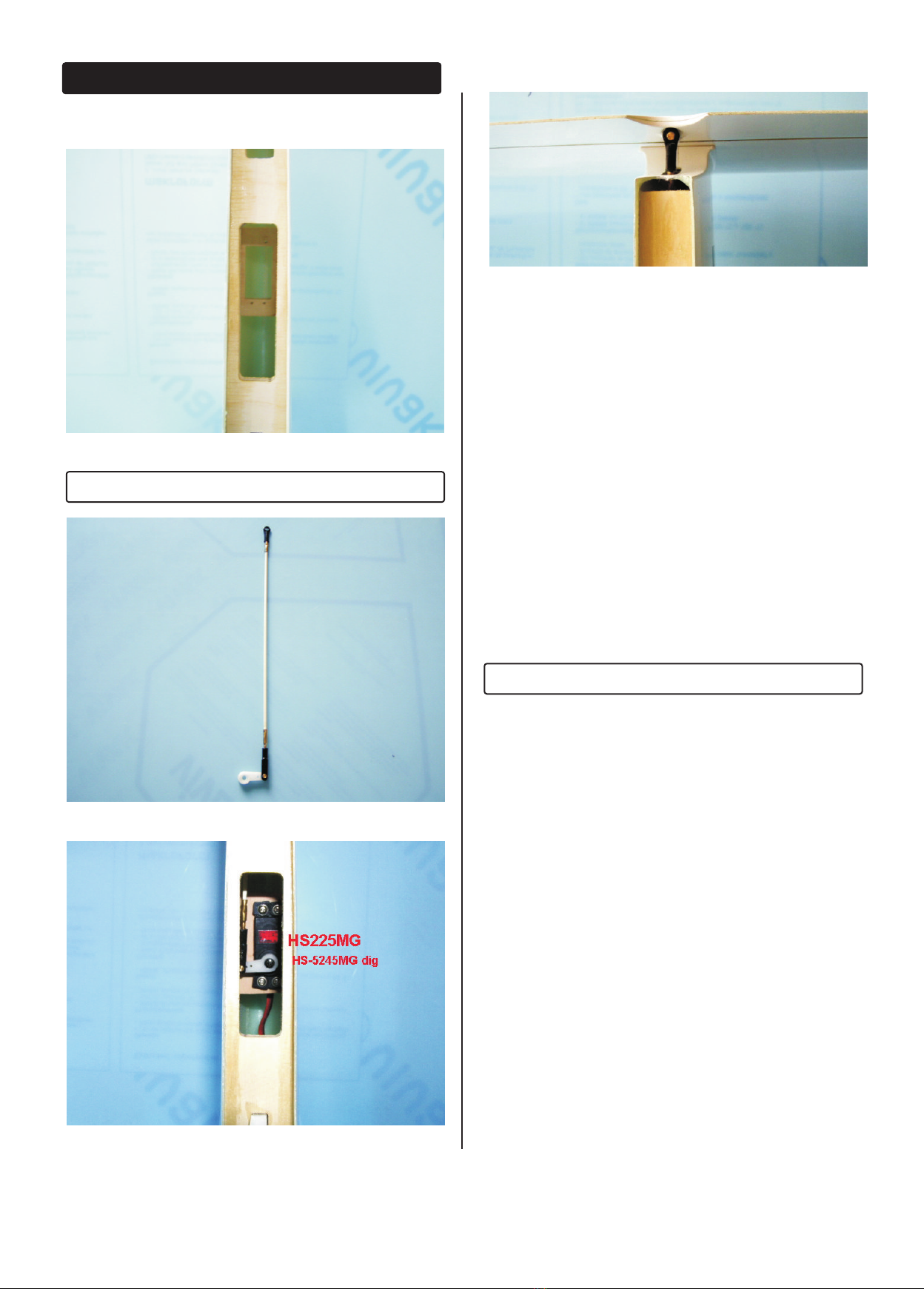
control). The servos recommended for
this airplane are good quality servos with at least
3.5kg-cm and metal gears for ailrons/flaperon of
torque such as the Futaba® S3150MG Micro servo.
Should you choose a different brand of servo, make
sure they use slop-free gears and that they center well
and fit in place. Lower quality servos can cause flutter
and destroy an airplane quickly.
Our recomandation:
- ailerons: FUTABA S3150MG
- ruder, elevator: FUTABA S3050MG
Additional things needes:
- 2pcs. of servo extensions cords of cca 600mm
- 3pcs. of servo extensions cords of cca 900mm
- switch harness with charging cable
- RX battery, 4.8 or 6.0V. For long thermal flying is
better to choose high capacity batteries ( 4000
or4800mAh )
- servo locks 2pcs., for easier mounting of servos
- EPOXY and CA glue
- Flat screwdriver and sharp cutting knive
PROTECT YOUR MODEL,YOURSELF
& OTHERS...FOLLOW THESE
IMPORTANT SAFETY PRECAUTIONS
INTRODUCTION
Accesoriess Needed
2

Replacment parts
Replacement parts for our planes are available
using the order numbers in the Replacement Parts
List that follows. The fastest, most economical service
can be provided by your hobby dealer or mail-order
company.
To locate a hobby dealer, visit our web site at
www.topmodeltehnik.com. Choose “Dealers” at the
bottom of the menu on the left side of the page.
Follow the instructions provided on the page to
locate European or International dealer. If a hobby
shop is not available, replacement parts may also
be ordered from
10 1001 Fuselage white GFK
10 1002 Canopy transparent
10 1003 Canopy & Frame glued
10 1009 Stickers
10 1020 Wings ARF - pair
10 1021 Elevator white GFK
10 1022 Rudder white GFK
www.toprc.eu
Before starting to build, take an inventory of this kit
to make sure it is complete, and inspect the parts to
make sure they are of acceptable quality. If any
parts are missing or are not of acceptable quality, or
if you need assistance with assembly, contact yuor
resseler. When reporting defective or missing parts,
use the part names exactly as they are written in
the Kit Contents list.
KIT CONTENTS
1. Fuselage white GFK
2. Canopy & Frame glued
3. ABS cokpit
4. Stickers
5. Wings ARF- pair
6. Elevator white GFK
7. Rudder white GFK
8. Wing bag accessories:
- servo covers x2
- servo pushrods x2
- clevises, nuts M2, cuplers M2 x4
- GFK small horns x2
9. Tail bag accessories:
- last closing rib plywood 6mm
- 2 x servo support plywood 6mm
- screw 4mm x 2
- rudder hinges x2
- rudder control horn BRASS M3
- GFK elevator control horn
10. Tail bag fuselage:
- steel wire pushrods 3mm x1
- plywood servo tray x 2
- wing joiner steel 16mm x1
- wing joiner 4mm x2
- M2 connectors, clevises M2, nuts M2 xv2
11. Instructions
3

WINGS
4
1. Using epoxy, glue the 4mm plywood final rib inside
the fuselage where shown. Before doing it, assure
that rudder have enough space for moving left an
right. You can firstly fix the plywood with few points
of CA glue. After checking that it's on right position
pull the rudder with hinges out and use plenty of
glue to fill any unevenness inside the fuselage.
2. Using epoxy, glue the rudder with hinges inside
the rib. Position the fuselage with nose down when
doing it. In this way the glue will not run in to the
rudder and stopped the moving of it. Dismounting
the rudder is easy, with pulling out a 2mm steel wire
bellow of the rudder.

ASSEMBLE THE FUSELAGE
Mount the Elevator
1. Inspect the hinges and the hinging motion of the
elevator now and before each flight. Cut the 52mm
nylon bolts to 19mm long. Attach the stab to the
fuse using the two nylon bolts. Be careful not to
overtighten.
2. Cut the remaining small control horn as shown.
The horn is installed centered on the opening in the
top of the fin and thebase of the horn is 1/2" [12mm]
back from the hinge line. Install the control horn
using two 2-56 x 5/8" [16mm] bolts and the nylon
backplate. Remove the stab from the fuselage.
3. Glue the GFK control horn in the elevator. Clean
the excess off epoxy with alcohol.
5
Mount the Servos in the fuselage
1. Glue the plywood servo tray doublers to the
plywood servo tray using CA.
2. Trial fit the servo tray where shown. You may need
to sand the edges slightly for the best fit. NOTE: If you
are using tall servos, you should install the servo tray
with the doublers up to provide a little more
clearance.
3. Glue the tray in place using epoxy. Note: Rough
up the fiberglass with sandpaper and clean with
isopropyl alcohol for a good glue bond.
4. Install the elevator and rudder servos. Make sure
they are oriented as shown. Route the servo leads to
the front of the plane.

1. Make the Z - Bend on the two steel wires 0.8mm.
2. Connect the Z-bend to the elevator and rudder
control horn & reinstall
the stabilizers while sliding the pushrod into the fins to
the elevator servos.
3. Temporarily, plug the elevator and rudder servos
into the receiver and turn on the transmitter and
receiver. Center the sticks and the trims.
4. With the elevator and rudder held at center, mark
the pushrod where it crosses the servo connections –
cca 8mm after.
5. Cut off the excess pushrods.
Install the Elevator and Rudder Pushrods
Install the Receiver and Battery
1. Wrap the receiver battery with 1/4" foam rubber
and install it as far forward in the nose as possible.
2. If you are using old RC system , extend the
antenna and route through the inside of the
fuselage towards the tail.Try to keep it as straight as
possible.
3. Wrap the receiver in 1/4" foam rubber and
position behind the battery. Route the servo
extension wires under the servos to the wing saddle
area.
4. Install the switch in front of the servos on the tray.
Use a scrap piece of light ply to make a mount that
fits your particular switch.
5. Hook up all the servos to your receiver.
NOTE: Consult your radio's instruction manual for
proper connection.
6
BALANCE THE MODEL
NOTE: This section is VERY important and must not be
omitted! A model that is not properly balanced will
be unstable and possibly unflyable.
1. The balance point (Center of Gravity) is 3-1/4"
[82mm] from the leading edge of the wing. This is
the balance point at which your model should
balance for your first flights. Later, you may wish to
shift the balance up to 1/2" [13mm] behind this point
to change the flying characteristics. Moving the CG
forward will add stability but it will decrease the
overall performance of the sailplane. Moving the
balance back makes the model more agile with a
lighter and snappier “feel” and improves the
sailplane's response to air currents. However, it will
also make the model less stable and can cause the
sailplane to “tuck under” or dive when its flying
speed increases.
2. With the wing attached to the fuse and all parts
of the model installed (ready to fly), lift the model by
picking it up with your fingertips at the C.G. If the tail
drops when you lift, the model is “tail heavy” and
you must add weight to the nose to balance. If the
nose drops, it is “nose heavy” and you must add
weight to the tail to balance. The model should
hang with a slight nose down attitude. Add BB's or
lead to the nose.
Set the control throws
Use a Great Planes AccuThrow™ (or a ruler)or similar
tool to accurately measure and set the control
throw of each control surface as indicated in the
chart that follows. If your radio does not have dual
rates, we recommend setting the throws at the
middle of both rate settings.
Note: The throws are measured at the widest part of
the elevators, rudder and ailerons.
O
15mm
15mm
0
8mm
8mm

0
15mm
7mm
85 mm
7

L
D-8028
AS 28
W
D-8028
28
28
Table of contents