pencil outline430mmx250mm,usingthiscardasamarkingtemplateandcutout
a hole in the ceiling (it may be safer to mark the position from above the ceiling
where obstructions are clearly visible, rather than from inside the room).
4) Make sure a distance between the edges and wall is no less than 400mm. There
should be a minimum of 220mm from the ceiling to any objects above, and
make sure a minimum distance of 1m is maintained between the appliance and
any illuminated flammable materials.
Bathroom Heater/Exhaust Fan
240V~ 50Hz 610W T IPX2, 2x 275W Heat Lamps
VBHE-2L
IMPORTANT INSTALLATION, USER & WARRANTY INSTRUCTIONS
GENERAL SAFETY WARNINGS
IMPORTANT CONSIDERATIONS BEFORE INSTALLING
INSTALLATION
Please read these instructions carefully before installing and using the appliance. Keep
the instructions handy for future reference.
IMPORTANT: This appliance does not come with a cord or a plug. It must be installed in
accordance with national and local council building regulations, and the Australian and
New Zealand wiring rules AS/NZS 3000 latest edition thereof.
ALL ELECTRICAL WORK MUST BE CARRIED OUT BY A LICENSED ELECTRICAL CONTRACTOR
OR ELECTRICIAN.
CAUTION: The appliance should not be installed directly above a bath, shower or fixed
water container. The appliance must not be installed in a position where water may
splash onto the appliance.
PLEASE READ ALL INSTRUCTIONS CAREFULLY BEFORE USING THE APPLIANCE.
To reduce the risk of fire, electrical shock or injury to persons or property:
1. Use this appliance only as described in this manual. Any other use not
recommended by Voltex Electrical may cause fire, electric shock, or injury to
persons and void thewarranty. If you have questions, please contact Voltex
Electrical at first.
2. Always operate the appliance from a power source of the same rated voltage,
frequency and power input as indicated on the appliance identification plate.
3. This appliance is intended for household use and similar applications only. It is
not suitable for use in an environment heavily laden with dust.
4. This appliance is not intended for use by persons (including children) with
reduced physical, sensory or mental capabilities, or lack of experience
and knowledge, unless they have been given supervision or instruction
concerning use of the appliance by a person responsible for their safety. Children
should be supervised to ensure that they do not play with the appliance.
5. Do not operate any appliance that malfunctions, or is dropped or appears
damaged in any way.
6. There are no user-serviceable parts inside the appliance. Contact your local
electrician if servicing or maintenance is required.
7. This appliance is designed for indoor use only.
8. Do not allow any foreign object to enter through the fascia opening or the rear of
the appliance as this may damage the appliance and/or the user.
9. WARNING: The appliance shall, under no circumstances, be covered with insulating
material or similar material.
10. Make sure that the power is OFF before installation.
11. Do not locate the appliance immediately below a socket-outlet. When cutting into the
mounting surface, do not damage electrical wiring and other hidden utilities.
12. The appliance must be properly connected to the protective earthing conductor in
the installation wiring of the installation.
13. WARNING: Curtains and other combustible material may ignite if in contact with the
appliance or if the appliance is installed too close.
14. Precautions must be taken to avoid the back-flow of gases into the room from the
open flue of gas or other fuel-burning appliances.
15. FOR SAFE USE OF THIS APPLIANCE, AFTER INSTALLATION, DISCONNECTION OF THE
APPLIANCE FROM THE SUPPLY SHALL BE POSSIBLE. THIS MAY BE ACHIEVED BY HAVING
THE PLUG ACCESSIBLE OR MEANS FOR ALL POLE DISCONNECTION MUST BE
INCORPORATED IN THE FIXED WIRING IN ACCORDANCE WITH THE WIRING RULES.
A few minutes planning can make a big difference to the installation time and to your
satisfaction with the function of the appliance.
1) This product is IPX2. It should not be installed directly above a shower or a bath where
is could come into contact with water.
2) For the exhaust fan to work efficiently, replacement air of a volume equivalent to
what is being extracted must be able to enter the room. In general, this air would be
drawn under the door, or through a slightly open window. If the room is airtight, the
fan will function poorly.
3) This appliance is designed for installation in flat ceilings ONLY. Do not mount it on a
sloping ceiling or a vertical wall.
4) Before commencing any cutting, check that there are no obstructions such
as ceiling joists and that there is sufficient height clearance for the housing and
routing of the duct. Check that the electrical wiring can be routed from the wall
switches to the mounting location.
5) This product has been designed for use on ceilings between 2.4 and 2.7m in height
and must be installed with the lowest point at least 2.1m above the floor. The InfraRed
lamps are not designed to heat the entire room area, they provide instant heat to
persons standing directly below them. Install above the area where‘drying off’ usually
occurs.
1) Locate in accordance with the requirements of the wiring rules relating to damp
situations. National and local council regulations concerning the discharge of air
must also be fulfilled.
2) Disassemble the unit before installation. Unscrew the heat lamps, and unfasten the
fascia-retaining springs inside the housing. Unplug the LED at the connector and
remove the fascia.
3) Choose a suitable mounting location in the ceiling. Mark the ceiling with a
CAUTION: Ensure that the intended hole will have suitable room to locate the unit and that
it will not interfere with joists or the ceiling structure. Joists, beams and rafters shall not
be cut or notched to install the appliance.
5) Insert the unit into the hole, ensuring that the side springs are pulled inwards so
that the unit can pass through the hole, without damaging the plaster. Secure
the unit to the ceiling using the supplied screws.
6) Plug in the downlight, reattach the springs to hold the fascia in place, and screw
in the heat lamps.
7) For installation where external venting is required, locate a suitable location to
vent out the exhausted air and cut out the hole. Put one end of a Ø125mm
flexible duct into the vent hole and seal space around the hole using a suitable
sealant and cowling where necessary. Keep the ducting as straight as possible
to maximise the performance of the fan.
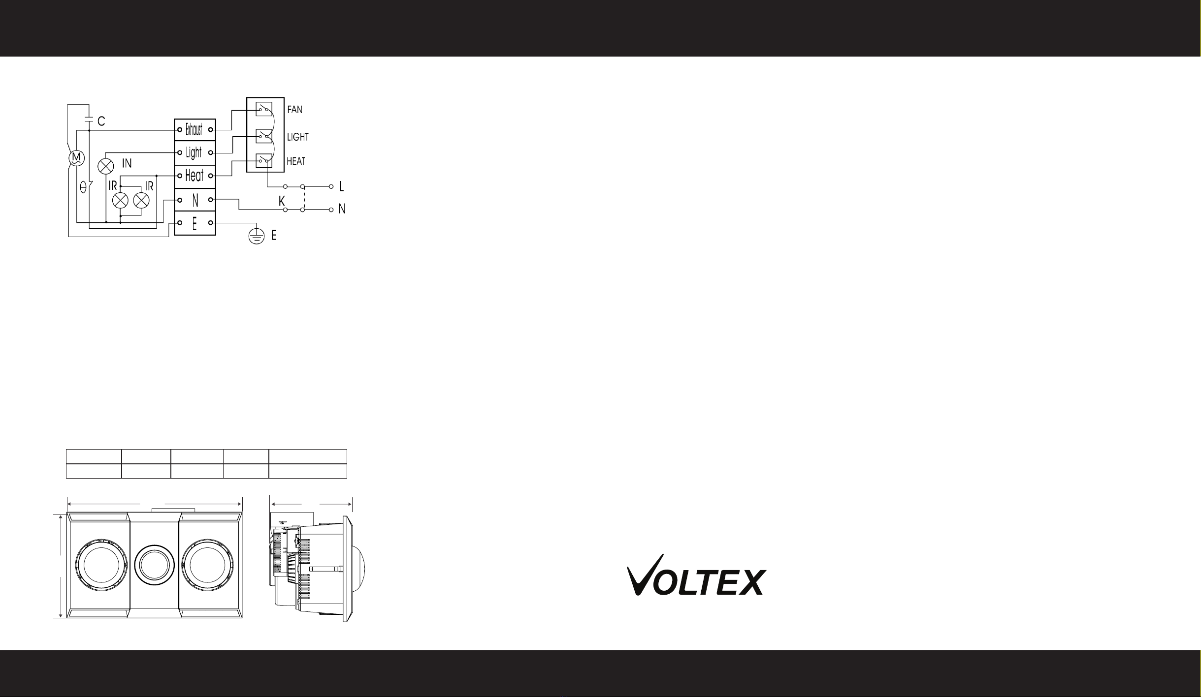
8) Wire the unit as shown in the figure below, ensuring compliance with AS/NZS
wiring rules. Fixed wiring insulation must be protected (e.g. by insulating sleeve)
Read and save these instructions! Please use this card as a hole cutting template 430mm x 250mm
400MM
D = 220MM
INSTALLATION INSTRUCTIONS AND HOLE CUTTING TEMPLATE