Vook VS-K300 User manual

VS-K300 VOOK
VERSION : 1.0
Operation Manual of 3 Axis Joystick LCD Keyboard
with 4 ch. Video input and LCD display
VS-K300
Pleased read the manual carefully before using the product.

VS-K300 VOOK
- 1 -
INDEX
1. SUMMARY--- ---------------------------------------------------------------------------------------------------3
2. SPECFICATION ------------------------------------------------------------------------------------------------3
3. TECHNICAL PARAMETER -------------------------------------------------------------------------------------3
4. BACK FACEPLATE -------------------------------------------------------------------------------------------3
5. FRONT FACEPLATE-------- ----------------------------------------------------------------------------------4
6. EXTERIOR CONNECTION ----------------------------------------------------------------------------------4
7. OPERATION -----------------------------------------------------------------------------------------------------5
8. FAULT ELIMINATING ---------------------------------------------------------------------------------------14

- 2 -
SAFETY MEASURE
Please observe the following safety measures, when install and use such product:
1. Please read and keep this manual.
2. The installation and maintenance of such product should be operate under the operation regulations by
professional.
3. Please do not install the product on the table or bracket unstably.
4. Please read carefully and understand the all information of this manual before install and use this product, and
keep it as a reference.
5. Please do not let any eyewinker or liquid matter filter to the product.
6. Use this product according to the warning sign and the direction.
7. Please pull out the power supply, before clear such product. Do not use the liquid or spray cleaner.
8. Only use the power supply style marked on the product: DC 12V/2.0A.

- 3 -
1. SUMMARIZE
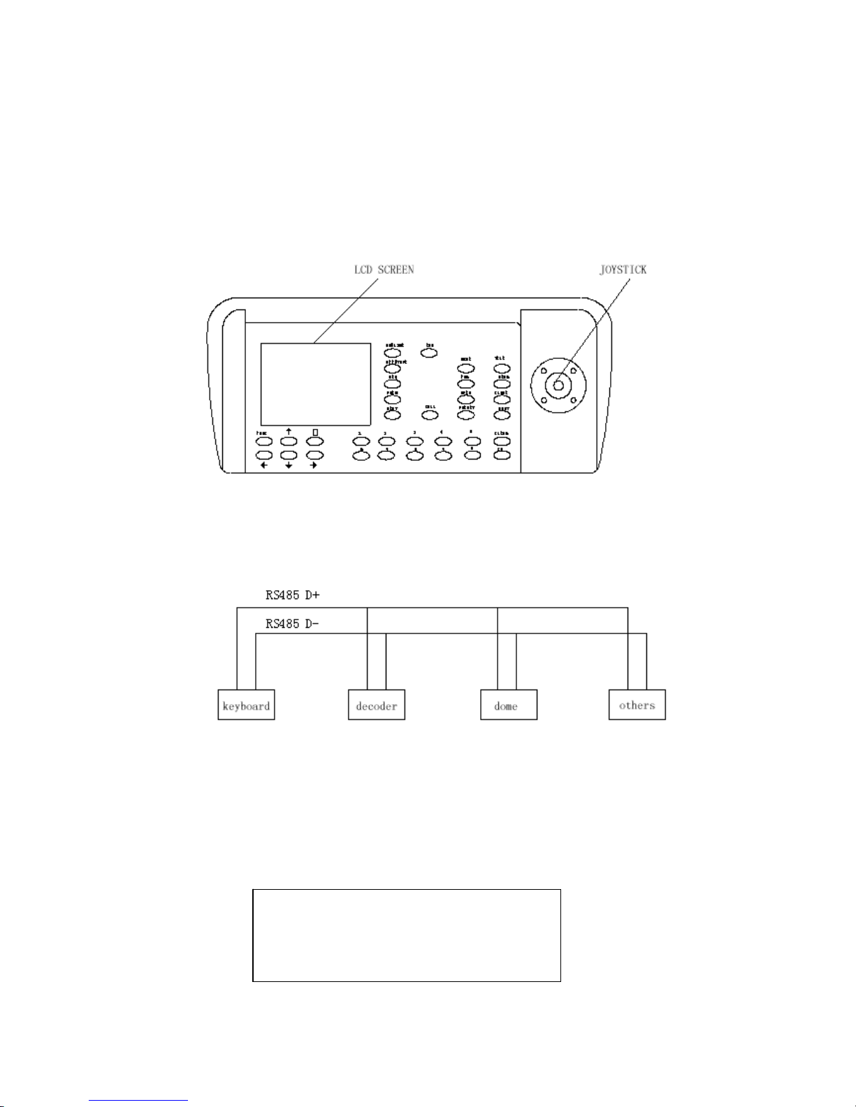
Such Keyboard is a product supporting with Intelligent Dome, decoder and other terminal receivers. It
connects to the receiver by EIA/RS-485 electric interface. Without the bus driver, one keyboard may control
domes or decoders up to 32 sets, and the longest communication distance is 1.2Km. The intelligent dome camera
can be controlled and setup instantly by such control keyboard, and it can also control the terminal decoder
directly, reaching the controlling to Pan/Tilt, lens, IR torch, wiper and other image capture equipments.
2. SPECFICATION
z5” color LCD screen, display of a quad picture
zBuilt in quad processor, free switching between cameras
z3 Axis shift gear joystick
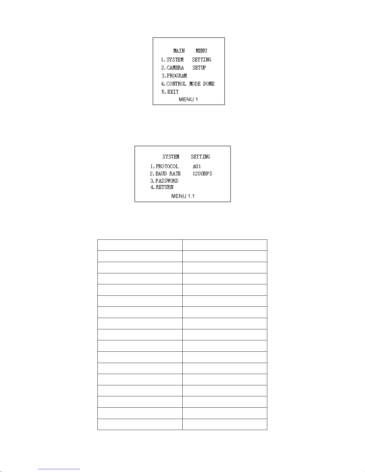
zOSD menu function
zIntegrated 16 protocols, baud rate range: 2400bps ~ 19200 bps
zRS-485 and RS-232 output can control many front equipments, including intelligent dome camera, decoder,
image processor etc.
3. TECHNICAL PARAMETER
zThe communication mode from dome camera to keyboard: Asynchronous Interface Half Duplex Serial
Communication
zBaud rate: 2400bps, 4800bps, 9600bps, 19200bps
zCommunication distance:: upto 1200 meters
zPower supply: DC12V/2.0A
zMeasure: 390×165×80 (mm)
zWeight: 2 Kg
zThe amount to control the Pan/Tilt or Dome: at most 32 pcs.
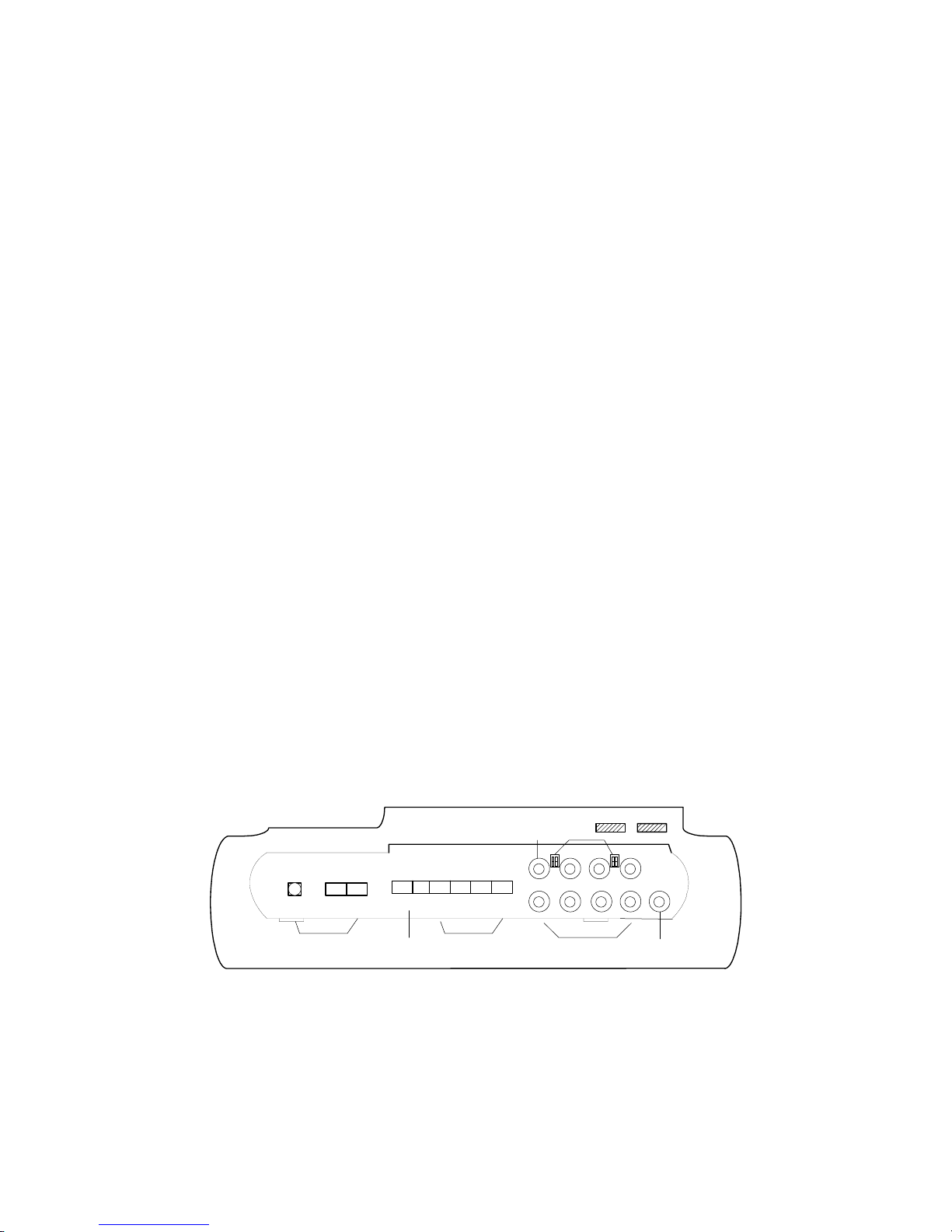
4. BACK FACE PANEL
POWER
GND DC12V TXD
IN
RS232 OUT
GND - + - +
RS485
OUT 1234
MON
DC12V
①②③
④
⑤⑥
⑦
⑧⑨
Figure1
① DC power supply input: DC12V/2.0A.
② RS232 output: to control the exterior image processor.
③ RS485 output: to control the dome camera or the Pan/Tilt.
④ Video input: 4 video input end, to connect four camera or other standard video signal source.

- 4 -
⑤ 4-channel Looping camera video output: to connect to the assistant monitor
⑥ Monitor output: to connect to the output end of the monitor
⑦ Impedance matching switcher: the corresponding impedance matching switcher should be switched to
the , when there is load of the looping output end
⑧ Brightness Knob
⑨ Contract Knob
5. FRONT FACE PANEL
Figure 2
6. EXTERIOR CONNECTION
Do not cross connect the keyboard to other equipment, they should be correctly connected as anode to anode
and cathode to cathode.
Figure 3
7. OPERATION
When power on, there will be display of the address of working camera, baud rate, protocol code and version code,
such information will be displayed for 10 seconds. User can bypass this by operating the keyboard directly, the
information will be disappeared automatically.
For instance: Displaying information as following:
It means the current address is 001, the baud rate is 2400bps, the protocol code is P003(the corresponding
CAMERA ID:001
BAUD RATE:2400BPS
PROTOCOL :P003
VERSION :V1.0

- 5 -
relations of the protocol code with the protocol will be listed in Table 2), the version code is V1.0. After 10
seconds, it will be displayed on LCD, the content of input data buffer and the current address will be displayed at
the very end bottom of the screen. As the following picture, the input data is 0000, and the current address is 001.
NB: Please setup the address, protocol and the baud rate of the keyboard same as the dome or Pan/Tilt,
before control it, may the dome or Pan/Tilt will be out of control by communication failure.
7.1.1. modify the dome address CAM
zpress number: “1-1024”
zpress key: CAM
After modify, the area of current address will display the address # inputted
7.1.2. lens become wide: WIDE
7.1.3. lens become tele: TELE
7.1.4. focus become far: FAR
7.1.5. focus become near: NEAR
7.1.6. aperture become opening: OPEN
7.1.7. aperture become closing: CLOSE
7.1.8. setup the preset position: PRESET
zpress number: “1-128”
zpress: PRESET
7.1.9. call preset position CALL
zpress number: “1-128”
zpress: CALL
7.1.10. start up tracking
zpress number: “1-6”
zpress: SHOT
7.1.11. setup the left point of the line scanning
zpress: AUTO
zpress: ON
7.1.12. setup the right point of the line scanning
zpress: AUTO
zpress: OFF
7.1.13. running the line scanning
zpress: AUTO
zpress: SHOT
Explain: some protocols do not need to setup the line scanning, just run the line scanning directly. After running, if
DATA:0000 ID:001

- 6 -
the dome or Pan/Tilt is out of control, probably the protocol adopted doses not support line scanning
7.1.14. open the assistant function
zpress: FUNC
zpress number: “1-10” different # stands for different function, refer to the Table 1
zpress ON
Table 1(if the function is out of control, probably such protocol is not support such operation)
KEYBOARD OPERATION
NUM CONTROL OBJECT FUNC+N+ON FUNC+N+OFF
0 Camera Power Supply/Reset On/ Off Switchable
Back to the Initial
Value of the Camera
1 Backlight Compensation On Off
2 Zero Lux(refer to camera function)On Off
3 Menu/Screen(refer to camera function)On Off
4 Digital Magnification On Off
5 Background Light of Sreen On Off
6 Focus Auto Manual
7 Iris Auto Manual
8 Auto Manual
9 Indoor Outdoor
10
White Balance
ATW On e Pu s h W B
7.1.15. close the assistant function
zpress: FUNC
zpress: “1-10” the function of different number refer the Table 1
zpress: OFF
7.1.16. control of dome / Pan/Tilt
Move the joystick until the camera reaches desired position. To reach the fastest spin of camera, move the
joystick utmost from center. Twist the joystick clockwise to zoom in and counterclockwise to zoom out.
7.1.17. the operation of keyboard menu
Press MENU to enter menu press again to exit menu. After enter the menu, move the joystick up or down to
move the cursor up or down; move the joystick left or right to adjust the content of current menu. If the option
of PASSWORD is ON, the screen will display: ENTER PASSWORD:[ ], to tip user input the 6-digit
password; If the option of PASSWORD is OFF, press MENU, to enter the MAIN MENU directly:

- 7 -
SYSTEM SETTING On “SYSTEM SETTING”, move the joystick to right, display the submenu “SYSTEM
SETTING”. Move the joystick up or down to choose the menu item, and move the joystick right or left to setup
the parameter.
¾PROTOCOL At such item, move the joystick right or left to display: P000—P001—P002—P003—P004—
P005—P006—P007—P008—P009—P010—P011—P012—P013—P014—P015 16 kinds of protocols. The
corresponding of the protocol code and protocol name as following:
Table 2
CODE NAME
P000 A01
P001 VOOK B01
P002 SANTACHI
P003 PELCO-D
P004 PELCO-P
P005 PANASONIC
P006 LONGCOMITY
P007 HD600
P008 LILIN
P009 VICON
P010 MOLYNX
P011 KALATE
P012 VCL
P013 RESERVED
P014 ALEC
P015 ULTRAK

- 8 -
¾BAUD RATE At such item, move the joystick right or left to choose the four baud rates:
2400bps—4800bps—9600bps—19200bps
¾PASSWORD At such item, move the joystick right or left to display the submenu as following:
PASSWORD SETTING
¾PASSWORD ON/OFF At menu item “PASSWORD ON”, move the joystick right, to switch the
ON/OFF of PASSWORD. If switch to ON, the user should input the 6-digit password to enter the menu next
time.
¾CHANGE PASSWORD At menu item “CHANGE PASSWORD”, move the joystick right, to display the
submenu as following:
CHANGE PASSWORD
¾NEW PASSWORD input the 6-digit password
¾CONFIRM confirm the 6-digit password at such item, press OPEN to confirm the password after input. If
the input 6-digit password same to the NEW PASSWORD, to display “PASSWORD CHANGED!”, or to
display “INVALID PASSWORD!” for 3 seconds.
¾RETURN move the joystick at such item, return to the menu (PASSWORD SETTING)
¾RETURN move the joystick at such item, return to the menu (SYSTEM SETTING)
¾RETURN move the joystick at such item, return to the menu (MAIN MENU)
CAMERA SETTUP At the main menu item “CAMERA SETTUP”, move the joystick right to display the
submenu “CAMERA SETTUP”. Move the joystick up or down to choose the menu item and move the joystick
right or left to setup the parameter.

- 9 -
¾BACK LIGHT ON move the joystick at such item right or left to switch the back light ON/OFF.
¾ICR SHOT AUTO move the joystick at such item right or left to switch the ICR SHOT ON/OFF.
¾IRIS AUTO move the joystick at such item right or left to switch the IRIS AUTO/MANUAL.
¾D-ZOOM ON move the joystick at such item right or left to switch the Digital ZOOM ON/OFF.
¾FOCUS AUTO move the joystick at such item right or left to switch the FOCUS AUTO/MANUAL.
¾WB SET AUTO move the joystick at such item right or left to switch the WHITE BALANCE SET
among AUTO—MANUAL—OUTDOOR—INDOOR—ATW—ONEPUSH.
¾COLOR OF CAM move the joystick at such item right or left to switch the camera image BW/COLOR.
¾MENU OF CAM switch the menu or screen ON/OFF.
¾RETURN move the joystick at such item right or left to return MAIN MENU
PROGRAM At the main menu item “PROGRAM”, move the joystick right to display the submenu
“PROGRAM”. Move the joystick up or down to choose the menu item, and move the joystick right or left to setup
the parameter.
¾AUTO PAN START POS move the joystick at such item right or left to set the current position of Pan/Tilt
or dome as the start point of the line scanning.
¾AUTO PAN END POS move the joystick at such item right or left to set the current position of Pan/Tilt or
dome as the end point of the line scanning.
¾RUN AUTO PAN NORMAL move the joystick at such item right or left to run the line scanning from the
start point to the end point.
¾SET PATROL move the joystick at such item right or left to change the tracking number among 01-06. To

- 10 -
press OPEN to enter the submenu of tracking edit. At such submenu, move the joystick right or left to move
the active cursor right or left, and move the joystick up or down to add or reduce the content of current menu
item. SEQ:XX(XX is the current editing tracking number), after edit the tracking, press CLOSE to exit and
save the current setup.
¾RUN PATROL move the joystick at such item right or left to change the tracking number among 01- 06.
And press OPEN to run the tracking.
¾RECORD PATTERN move the joystick at such item right or left to enter the RECORD PATTERN.
¾RUN PATTERN move the joystick at such item right or left to run PATTERN.
¾RETURN move the joystick at such item right or left to return the MAIN MENU.
CONTROL MODE At the main menu item “CONTROL MODE”, move the joystick right, and the keyboard
control will be switched between DOME and IMAGE PROCESSOR. Such function aims to the multiplex key:
ON/LIVE and OFF/TAPE. Or press FUNC+NEXT(press such two keys together)to switch between DOME
and IMAGE PROCESSOR too.
7.2. the operation of image processor
7.2.1. fullscreen
7.2.2. picture in picture (invalidation)
7.2.3. four images
7.2.4. nine images (invalidation)
7.2.5. sixteen images (invalidation)
7.2.6. display the former image PREV
7.2.7. display the after image NEXT
7.2.8. auto jumping SEQ press again to cancel it
7.2.9. the menu operation of image processor
Notice: Device contents of menu have been setup before leaving factory, data changing on this device is
prohibited. Any changing on the PROTOCOL and BAUD will lead the image processor out of control
( refer to SYSTEM SET option)。
7.2.9.1. the basic operation of menu

- 11 -
enter/exitmenu pressFUNC& together(for short FUNC+ )
move the menu cursor up press FUNC &
<
together(for short FUNC+
<
)
move the menu cursor down press FUNC &
<
together(for short FUNC+
<
)
enter the submenu SEQ
modify the content of current menu TAPE
the operation of entering password as input 1-------- input number 1, and press CAM
as input 2-------- input number 2, and press CAM
as input 3-------- input number 3, and press CAM
as input 4-------- input number 4, and press CAM
7.2.9.2 the operation of menu
press “FUNC+ ”, display to input the purview password, the image is as following:
PASSWORD:[_ ]
Input the password: 1111, to enter the main menu:
The system will exit the menu and return to the image before, after no operation for 3 mins.
SYSTEM SET select the item “SYSTEM SET” in main menu, and press “SEQ”, to display the submenu
“SYSTEM SET”. Use FUNC+
<
)(FUNC+
<
)to move and choose the menu item, and use
FUNC+
v
)or(FUNC+
v
)to setup the parameter.
MAIN MENU
1. SYSTEM SET
2. CAMERA SET
3. SCREEN SET
4. EVENT LIST
5. RESET DEFAULT
SYSTEM SET
TIME: 2006/03/04 16:43:16
FORMAT: ASIA [YYYY/MM/DD]
LIVE TIME DISP: TOP
BORDER DISP: GRAY
BACK COLOR: BLUE
BUZZER: OFF
ALARM TIME: 020 SEC
FREEZE TIME: 010 SEC
PASSWORD: 1111
TV FORMAT: PAL
PROTOCOL: PTC1 BAUD:9600(BPS)
DEVICE ID: 01(HEX)
QUTPUTFORMAT:CVBS

- 12 -
¾TIME:system date,YYYY/MM/DD system time,HH/MM/SS.
¾FORMAT:[ASIA;U.S.;EURO].
¾LIVE TIME DISP: the position of live time displaying [TOP;TOP_LEFT;TOP_RIGHT;NON]
¾BORDER DISP:border color [GRAY ,WHITE,BLACK ,OFF].
¾BACK COLOR:background color [BLUE,BLACK].
¾VFILTER:vision filter [ON: gentleness,OFF: clear].
¾BUZZER:buzzer alart[ON,OFF].
¾ALARM TIME:the holding time for alarm output。[003―255] seconds.
¾FREEZE TIME:[000―255] seconds, 000 second is mean freeze for unlimited time.
¾PASSWORD:manager password [1111―4444],can setup any four-digit among 1―4.
¾FORMAT:video format [PAL,NTSC],PAL is the default.
¾PROTOCOL:[PTC1,PTC2,PTC3,PTC4].
¾BUAD:baud rate [1200,2400,4800,9600,19200]Bps.
CAMERA SET At main menu, choose the item “CAMERA SET”, and press “SEQ”, to display the
submenu “CAMERA SET”. Use (FUNC+
<
)(FUNC+
<
)to move and choose the menu item, and
use (FUNC+
v
)or(FUNC+
v
)to setup the parameter.
CAMERA MENU
CAM1
PICTURE DISPLAY: YES
TITLE DISPLAY: YES
CAMERA TITLE: CAM1
AUTO TIME: 02 SEC
MIRROR: OFF
PICTURE QUALITY [ ]
SENSOR SWITCH: ON
SENSOR LEVEL: LOW
DETECT TIME: 00:00 – 23:59
MOTION SWITCH: OFF
MOTION SET: [ ]
DETECT TIME: 00:00 – 23:59
ALARM OUT
LOSS NO SENSOR:YES MOTION:YES

- 13 -
¾CAM:the serial number of the camera image [1―4].
¾PICTURE DISPLAY:[YES ,NO] .
¾TITLE DISPLAY:the switcher of the camera name [YES: display,NO: disappear].
¾CAMERA TITLE:edit the camera name, can use any 10 letters, digits or symbol.
¾AUTO TIME:time of auto jumping [0―99] seconds.
¾PICTURE QUALITY :[refer to “ setup the picture quality”].
¾SENSOR SWITCH:[ON ,OFF ].
¾SENSOR LEVEL:the effective sensor level [HIGH: for high level,LOW: for low level].
¾DETECT TIME:the detect time of sensor alarm.
¾MOTION SWITCH:motion alarm switcher [ON,OFF].
¾MOTION SET :the setup of motion alarm [refer to 详见“the setup of motion alarm”].
¾DETECT TIME:the detect time of motion alarm.
¾ALARM OUT: (non)
¾LOSS:the alarm output of the camera signal losing [YES ,NO ]. (non)
¾SENSOR:the alarm output of the sensor [YES ,NO ] (non)
¾MOTION:the alarm output of the motion [YES ,NO ]. (non)
SCREEN SET(don’t need to adjust such item)
EVENT SET(don’t need to adjust such item)
SCREEN SET
OSD HORIZONTAL SET : 03
OSD VERTICAL SET : 01
PICTURE HORIZONTAL SET : 07
PICTURE VERTICAL SET : 03
PICTURESCALE SET :05
(DEFAULT)
EVENTLOG
NO CAM DATE TIME EVENT
001 :: 2006-3-1 14:07:01 P_ON
002 -- ------------ ---------- --------
003 -- ------------ ---------- --------
004 -- ------------ ---------- --------
005 -- ------------ ---------- --------
006 -- ------------ ---------- --------
007 -- ------------ ---------- --------
008 -- ------------ ---------- --------
009 -- ------------ ---------- --------
010 -- ------------ ---------- --------
PREVIOUS NEXT ERASE

- 14 -
¾NO: the recorder number of the alarm event,001―100, amount 100.
¾CAM: the camera image number of the alarm event.
¾DATE: the date of the alarm event.
¾TIME: the time of the alarm event.
¾EVENT: the reason of the alarm event.[P_ON, boot-strap alarm;LOSS,camera signal losing alarm;
MOTION,motion alarm;SENSOR,sensor alarm]
¾PREVIOUS: previous page. Ten recorders one page, amount 10 pages. Press “SEQ” to turn over the page.
¾NEXT: next page. Ten recorders one page, amount 10 pages. Press “SEQ” to turn over the page.
¾ERASE: erase all the alarm recorders, and record from 001 newly.
RESET DEFAULT press “SEQ” to confirm the YES to resume the setup left factory. And press “SEQ” to
confirm the NO to cancel it.
8. FAULT ELIMINATING
FAULT Circumstance Remedy
No image after boot-strap No power supply
1.Check the connection of power line
2.If the power supply is DC12V?
Can not control the appoint dome
or Pan/Tilt
1.Incorrect protocol
2.Incorrect baud
rate
3.Incorrect address
1.If the protocol is same between keyboard and
dome or Pan/Tilt?
2.If the baud rate is same between keyboard and
dome or Pan/Tilt?
others Send back to factory for service.
CONFIRM RESET
YES NO
Table of contents