Vortex86DX VDX-6354 User manual

VDX-6354 / VDX-6354-PLUS
DM&P Vortex86DX 800MHz
PC/104 CPU Module
with 4S/2USB/VGA/LCD/AUDIO/ LAN/GPIO 256MB DDR2
Onboard
User’s Manual
(Revision 1.1A)

Copyright
The information in this manual is subject to change without notice for continuous improvement in
the product. All rights are reserved. The manufacturer assumes no responsibility for any
inaccuracies that may be contained in this document. And makes no commitment to update or to
keep current the information contained in this manual.
No part of this manual may be reproduced, copied, translated or transmitted, in whole or in part,
in any form or by any means without the prior written permission of the manufacturer.
Copyright 2008.
Manual No. IUM6354000-01 Ver.1.0A December, 2008
Manual No. IUM6354000-01 Ver.1.1A February, 2009
Trademarks Acknowledgment
Vortex86DXis the registered trademark of the manufacturer.
Other brand names or product names appearing in this document are the properties
and registered trademarks of their respective owners. All names mentioned herewith
are served for identification purpose only.

T a b l e o f C o n t e n t s
T ab l e o f C o n t e nt s.............................................................iii
C h a p t e r 1 Introduction……………………………………………1
1.1 Packing List............................................................1
1.2 Product Description................................................1
1.3 Specifications.........................................................3
1.4 Board Dimension....................................................5
C h a p t e r 2 Installation……………………………………………..5
2.1 Board Outline.........................................................6
2.2 Connectors & Jumpers Location............................7
2.3 Connectors & Jumpers Summary...........................9
2.4 PinAssignments & Jumper Settings......................11
2.5 System Mapping...................................................22
2.6 Watchdog Timer...................................................25
2.7 GPIO....................................................................26
2.8 SPI flash...............................................................27
2.9 PWM....................................................................28
3.0 IDE to SD.............................................................29
C h a p t e r 3 Driver Installation……………………………………30
Appendix ………………………………………………………………..31
A. TFT Flat Panel Data Output......................................31
B. TFTFlat Panel Support List.......................................32
C. LVDS Flat Panel Support List....................................33
D. Flat Panel Hardware Setting.....................................34
E. Flat Panel Wiring and Lighting..................................35
F. TCP/IPlibrary for DOS real mode..............................36
G. BIOS Default Setting.................................................37
Warranty............................................................................................38

This page is blank

Vortex86DX-6354 Vortex86DXPC/104 CPU Module
1
C h a p t e r 1
Introduction
1.1 Packing List
Product Name Package
VDX-6354
&
VDX-6354-PLUS
Embedded Vortex86DX CPU All-in-One Board
Manual & Drivers CD x 1
RS232 cable x 4
PRINTER cable x1
IDE cable x 1
USB cable x 1 (USB port x 2)
VGA cable x 1
LAN cable x 1
GPIO cable x 1
AUDIO Line x2
PS/2 Mouse cable x 1
PS/2 Keyboard cable x 1
Screw Kit x 1

Vortex86DX-6354 Vortex86DXPC/104 CPU Module 2
1.2 Product Description
The VDX-6354 family of low-power x86 embedded controlleris designed to meet PC/104
specification, and integrated with the following features.
800 MHz Vortex86DX SoC
VGA, TFT/ LVDS LCD support up to
1280x1024 resolution
256 / 512MB DDR2 system memory
Enhanced IDE (UltraDMA-100/66/33)
10/100Mbps Ethernet
2 USB 2.0 (host)
Up to 4 serial ports
Parallel port
16-bit GPIOs
Audio
Onboard 4MB SPI Flash
PC/104-Plus expansion bus
Meet PC/104 stacking spec.
2 watchdog timer
16~24 PWM channels
JTAG interface
AMI BIOS
Single voltage +5V DC
Support extended operating
temperature range of -20°C to +70°C
The VDX-6354 PC/104 family of embedded controller is designed with backward compatibility in
mind, to provide migration path for projects facing end-of-life challenges with their existing x86
based PC/104 controller. The VDX-6354 family of controller is designed as a plug in
replacement, with backward compatibility to support legacy software to help extend existing
product life cycle without heavy re-engineering.
VDX-6354 is suitable for broad range of data-acquisition, Industrial automation, Process control,
Automotive controller,AVL, Intelligent Vehicle management devic,Medical device, Human
machine interface, Robotics, machinery controlAnd more…application that required small
footprint, low-power and low-cost hardware with open industry standard such as PC/104.

Vortex86DX-6354 Vortex86DXPC/104 CPU Module 3
1.3 Specifications
Features VDX-6354
CPU DM&P SoC CPU Vortex86DX- 800MHz
Real Time Clock with Lithium Battery Backup
Cache L1:16K I-Cache, 16K D-Cache L2:128KB Cache
BIOS AMI BIOS
Bus Interface PC/104 Standard Compliant (Optional: PCI-104)
System Memory 256 / 512MB DDR2 Onboard
Watchdog Timer Software programmable from 30.5 us to 512 seconds x2
sets(Watchdog 1 fully compatible with M6117D)
VGA XGI Volari Z9s Chipset
VGA and TFT Flat Panel Interface Support
LVDS Flat Panel Interface Support (Optional)
Onboard 32MB VGA Memory
Support resolution up to 1280 x 1024,16MB colors
LAN Integrated 10/100M Ethernet
AUDIO CM119 USB Audio controller
I /O Interface Enhanced IDE port (UltraDMA-100/66/33) x1
RS-232 port x3
RS-232/485/422 port x1 (RS485: Auto Direction)
Parallel port x1
USB port x2 (USB 2.0 version)
16-bit GPIO port x1
10/100Mbps Ethernet port x1
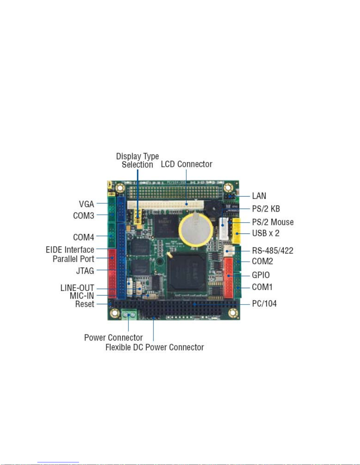
Connectors
2.00 mm 44-pin box header for IDE x1
2.00 mm 44-pin box header for LCD x 1
2.00 mm 10-pin box header for VGA x1
2.00 mm 10-pin box header for USB x1
2.00 mm 26-pin box header for Printer x1
2.00 mm 20-pin box header for 16-bit GPIO x1
2.00 mm 10-pin box header for RS-232 x4
2.00 mm 8-pin header for Ethernet x 1
2.54 mm 5-pin box header for Keyboard x1
2.54 mm 5-pin header for Mouse x1
2.54 mm 4-pin header for DC-in x1
2.54 mm 3-pin header for RS-485 x1
2.54 mm 2-pin header for Reset x1
2.54 mm 7-pin header for Redundancy x1(Opt)
2.54 mm 2-pin header for SYS-Fail-SW- x1(Opt)
1.25 mm 6-pin Wafer for JTAG x1
1.25 mm 4-pin Wafer for Line-out/MIC-in x2

Vortex86DX-6354 Vortex86DXPC/104 CPU Module 4
Flash Disk Support
Onboard 4MB SPI Flash Disk (Driver: A)
44-pin IDE Flash Disk( EmbedDisk 16MB or above)
44-pin IDE to Micro SD (Optional)
Power Requirement Single Voltage +5V @740mA
Dimension 90 X 96mm (3.54 x 3.77 inches)
Weight 90g
Operating
Temperature -20oC ~ +70oC
-40°C ~ +85°C (Optional)

Vortex86DX-6354 Vortex86DXPC/104 CPU Module 5
1.4 Board Dimension

Vortex86DX-6354 Vortex86DXPC/104 CPU Module 6
C h a p t e r 2
Installation
2.1 Board Outline
(Note1: PCI-104 connector is optional)
(Note2: Redundancy Signal and System-Fail-SW are optional)
(Note3: COM2 RS232/422/485 is selected by BIOS setting)

Vortex86DX-6354 Vortex86DXPC/104 CPU Module 7
2.2 Connectors & Jumpers Location
Connectors

Vortex86DX-6354 Vortex86DXPC/104 CPU Module 8
Jumpers & LEDs

Vortex86DX-6354 Vortex86DXPC/104 CPU Module 9
2.3 Connectors & Jumpers Summary
Summary Table
Nbr Description Type of Connections Pin nbrs.
J1 IDE Box Header, 2.0,22x2 44-pin
J2 USB Box Header,2.0, 5x2 10-pin
J4 LAN Pin Header, 2.0, 4x2 8-pin
J5 JTAG Wafer, 1.25, 6x1 6-pin
J6 Reset Pin Header, 2,54,1x2 2-pin
J7 Redundancy (Optional) Pin Header, 2.54, 7x1 7-pin
J8 System –Fail-Switch (Optional)
Pin Header, 2.54, 2x1 2-pin
J9 PS/2 Keyboard Pin Header, 2,54,1x5 5-pin
J10 PS/2 Mouse Pin Header, 2,54,1x5 5-pin
J11 COM1(TTL/GPIO-P4 / PWMx8)
Box Header, 2.05x2 10-pin
J12 COM2(RS232/RS485/RS422) Box Header, 2.05x2 10-pin
J13 GPIO ( Port 0 / 1 /PWMx16) Box Header, 2.0,10x2 20-pin
J15 RS-485 (Auto direction) Molex Header,2.54, 3x1 3-pin
J16 Power Connector Terminal Block 5.0,2x1 2-pin
J17 COM3 Box Header, 2.05x2 10-pin
J18 PRINT Box Header, 2.0, 13x2 26-pin
J19 COM4 Box Header, 2.05x2 10-pin
J20 PC104 Connector – 64 pin Box Header, 2.5432x2 64-pin
J21 PC104 Connector – 40 pin Box Header, 2.5420x2 40-pin
J22 4P Power Source (Interconnect
to PC/104 – J20) Pin Header, 2.54, 4x1 4-pin
J23 PC/104 + (Optional) Box Header, 2.0, 30x4 120-pin
J24 VGA Pin Header, 2.0,5x2 10-pin
J25 LCD Connector Box Header,2.0,22x2 44-pin
J26
J31
Display type Setup Pin Header, 2.54, 3x1 3-pin
J33 LINE-OUT Wafer, 1.25, 4x1 4-pin
J34 MIC-IN Wafer, 1.25, 4x1 4-pin
PWR-
LED
PowerActive LED (Red) LED-SMD

Vortex86DX-6354 Vortex86DXPC/104 CPU Module 10
IDE-
LED IDEActive LED (Green ) LED-SMD
MTBF-
LED
MTBF-Out (Orange) LED-SMD
LED 3 LAN Link/Active LED (Green) LED-SMD
LED 4 LAN Duplex LED (Yellow ) LED-SMD
SP1 BUZZER

Vortex86DX-6354 Vortex86DXPC/104 CPU Module 11
2.4 Pin Assignments & Jumper Settings
J1: IDE (44 Pins)
J2: USB
Pin # Signal Name
Pin # Signal Name
1 VCC 2 VCC
3 LUSBD3- 4 LUSBD2-
5 LUSBD3+ 6 LUSBD2+
7 GND 8 GND
9 GGND 10 GGND
Pin # Signal Name
Pin # Signal Name
1 IDERST 2 GND
3 IDED7 4 IDED8
5 IDED6 6 IDED9
7 IDED5 8 IDED10
9 IDED4 10 IDED11
11 IDED3 12 IDED12
13 IDED2 14 IDED13
15 IDED1 16 IDED14
17 IDED0 18 IDED15
19 GND 20 NC
21 IDEREQ 22 GND
23 IDEIOW 24 GND
25 IDEIOR 26 GND
27 ICHRDY 28 GND
29 IDEACK 30 GND
31 IDEINT 32 NC
33 IDESA1 34 IDECBLID
35 IDESA0 36 IDESA2
37 IDECS-0 38 IDECS1
39 IDELED 40 GND
41 VCC 42 VCC
43 GND 44 NC

Vortex86DX-6354 Vortex86DXPC/104 CPU Module 12
J4: LAN
Pin # Signal Name
Pin # Signal Name
1 ATX+ 2 ATX-
3 ARX+ 4 LED0
5 LED0+ 6 ARX-
7 LED1+ 8 LED1
J5: JTAG
Pin # Signal Name
Pin # Signal Name
1 VCC 2 GND
3 TCK 4 TDO
5 TDI 6 TMS
J6: RESET
Pin # Signal Name
Pin # Signal Name
1 RST_SW 2 GND
J7: Redundancy (Optional)
Pin # Signal Name Pin # Signal Name
1 GND 2 SYS-FAIL-OUT
3 SYS-FAIL-IN 4 GPCS0
5 SYS-GPCS-IN 6 TXD9\
7 RXD9\
J8: System-Fail-Switch (Optional)
Pin # Signal Name
1 SYS-SW-IN
2 GND

Vortex86DX-6354 Vortex86DXPC/104 CPU Module 13
J9: PS/2 Keyboard
Pin # Signal Name
Pin # Signal Name
1 KBCLK 2 KBDAT
3 NC 4 GND
5 VCC
J10: PS/2 Mouse
Pin # Signal Name
Pin # Signal Name
1 MSCLK 2 MSDATA
3 NC 4 GND
5 VCC
J11: COM 1 (Optional TTL/ GPIO-P4 / PWMx8)
Pin # Signal
Name Pin # Signal
Name
1 DCD1 2 RXD1
3 TXD1 4 DTR1
5 GND 6 DSR1
7 RTS1 8 CTS1
9 RI1 10 NC
J12: COM2 RS232 / 422 / 485 (Change setting by BIOS)
Pin # Signal Name Pin #
Signal Name
1 DCD2/ 422TX- / RS485- 2 RXD2 / 422TX+ / RS485+
3 TXD2 / 422RX+ 4 DTR2 / 422RX-
5 GND 6 DSR2
7 RTS2 8 CTS2
9 RI2 10 NC

Vortex86DX-6354 Vortex86DXPC/104 CPU Module 14
J13: GPIO (Port 0 / 1/ PWMx16)
J15: RS485 (Auto direction)
J16: Power Connector (Terminal Block 5.0mm)
Pin # Signal Name
1 +5V
2 GND
J17: COM3
Pin # Signal Name
Pin # Signal Name
1 DCD3 2 RXD3
3 TXD3 4 DTR3
5 GND 6 DSR3
7 RTS3 8 CTS3
9 RI3 10 NC
Pin # Signal Name
Pin # Signal Name
1 GND 2 VCC
3 GP00 4 GP10
5 GP01 6 GP11
7 GP02 8 GP12
9 GP03 10 GP13
11 GP04 12 GP14
13 GP05 14 GP15
15 GP06 16 GP16
17 GP07 18 GP17
19 VCC 20 GND
Pin # Signal Name
1 RS485+
2 RS485-
3 GND

Vortex86DX-6354 Vortex86DXPC/104 CPU Module 15
J18: PRINT
Pin # Signal Name
Pin # Signal Name
1 STB- 14 AFD-
2 PD0 15 ERR-
3 PD1 16 INIT-
4 PD2 17 SLIN-
5 PD3 18 GND
6 PD4 19 GND
7 PD5 20 GND
8 PD6 21 GND
9 PD7 22 GND
10 ACK- 23 GND
11 BUSY 24 GND
12 PE 25 GND
13 SLCT 26 NC
J19: COM4
Pin # Signal Name
Pin # Signal Name
1 DCD4 2 RXD4
3 TXD4 4 DTR4
5 GND 6 DSR4
7 RTS4 8 CTS4
9 RI4 10 NC

Vortex86DX-6354 Vortex86DXPC/104 CPU Module 16
J20: PC104 Connector – 64pin
Pin # Signal Name Pin # Signal Name
1 IOCHCHK * 2 GND
3 SD7 4 RESETDRV
5 SD6 6 VCC
7 SD5 8 IRQ9
9 SD4 10 -5V
11 SD3 12 DRQ2
13 SD2 14 -12V
15 SD1 16 OWS
17 SD0 18 +12V
19 IOCHRDY 20 GND
21 AEN 22 SMEMW *
23 SA19 24 SMEMR *
25 SA18 26 IOW *
27 SA17 28 IOR *
29 SA16 30 DACK3 *
31 SA15 32 DRQ3
33 SA14 34 DACK1 *
35 SA13 36 DRQ1
37 SA12 38 REFRESH *
39 SA11 40 SYSCLK
41 SA10 42 IRQ7
43 SA9 44 IRQ6
45 SA8 46 IRQ5
47 SA7 48 IRQ4
49 SA6 50 IRQ3
51 SA5 52 DACK2 *
53 SA4 54 TC
55 SA3 56 BALE
57 SA2 58 VCC
59 SA1 60 OSC
61 SA0 62 GND
63 GND 64 GND
This manual suits for next models
1
Table of contents
Popular Motherboard manuals by other brands

ASROCK
ASROCK CONROE1333-ESATA2 Quick installation guide

Analog Devices
Analog Devices EVAL-AD5325DBZ user guide

Nvidia
Nvidia TEGRA DG-04927-001_V01 user guide

Freescale Semiconductor
Freescale Semiconductor T4240 quick start

MPS
MPS EVKT-MP8860 user guide

SOYO
SOYO SY-D6IBA User's guide & technical reference