VSAIL VI-6811 User manual

VI-6811 Intelligent Fire Alarm
Panel
Installation and Operation Manual
(Ver 3.50, August 2019)
Tianjin VSAIL Intelligent Fire Technology Co.,Ltd

VI-6811 Intelligent Fire Alarm Panel Installation and Operation Manual
Tianjin VSAIL Intelligent Fire Technology Co.,Ltd I
Catalogue
Chapter I General Feature...........................................................................................................................................1
Chapter II Technical Data...........................................................................................................................................1
Chapter III Structure and Wiring................................................................................................................................1
Chapter IV Installation ...............................................................................................................................................4
Chapter V System setup..............................................................................................................................................4
Chapter VI Use and Operation....................................................................................................................................9
Chapter VII FaultAnalysis and Elimination............................................................................................................ 12
Chapter VIII Notes .................................................................................................................................................. 12
Chapter IX Transportation and Storage................................................................................................................... 13

VI-6811 Intelligent Fire Alarm Panel Installation and Operation Manual
Tianjin VSAIL Intelligent Fire Technology Co.,Ltd 1
Chapter I General Feature
VI-6811 Intelligent Fire Alarm Panel is a single-loop addressable panel with capacity up to 100 intelligent
devices. This panel is designed in a compact size with 1 LCD screen, 1 sounder output, 2 passive outputs and LED
indicators. The build-in memory is capable for 1000 event logs. In order for Firehouse Gateway, the panel is
programed as 8 logic zones with one sounder beaconVI-6737 and one output interface VI-6727 or VI-6721 of each.
VI-6811 is considered as an economic solution for small projects such as residential house, restaurant, hotel, bank
office, telecom stations, etc.
Chapter II Technical Data
2.1 Operate Voltage:
Main: AC 220V(187V~242V)/0.2A, 50Hz
Standby: DC12V/1.3AH (two pieces)
Protection voltage of standby: 11V-10.6V
Recovery voltage of standby: 11.5V-12.3V
Maximum input power: 40W
2.2 Loop capacity:
Maximum devices: 40 or 100addresses(device type: smoke detector, heat detector, multi detector, Manual call
point, sounder beacon, monitor interface, control interface, isolator)
Loop Voltage: DC15V~20V
Loop current: <50mA
2.3 Operating environment:
Ambient temperature: 0℃~45℃
Relative humidity: ≤95%RH(40℃±2 ℃)
Chapter III Structure and Wiring
3.1 Appearance and structural dimensions
Appearance and structural dimensions of the panel: Length*Height*Thickness=320 mm *240 mm *66mm, as
shown in Figure 3.1:
Figure 3.1

VI-6811 Intelligent Fire Alarm Panel Installation and Operation Manual
Tianjin VSAIL Intelligent Fire Technology Co.,Ltd 2
3.2 Installation dimensions
The installation dimensions are 200 mm *190mm*260mm, as shown in Figure 3.2:
2 0 0 m m
2 6 0 m m
1 9 0 m m
Figure 3.2
3.3 Panel description
The panel is shown in figure 3.3:
S--S m ok e D ete cto r
R e c o r d s
M a in P o w e r
S h i f t
A C F au lt
F ire A la rm
B at te ry
B A T F au lt
S o u n de r
M ute
C O M F au lt
S o u n de r F a ult
Sou n der S ea rc h C o n fig u re
T e s t R e s e rv e d M ute R e s e t
S y ste m C l o ck In i ti al F i re T im e D e v ic es
F ire F a ul t T i m e
H--H eat D e te ctor
M--M a nu a l C a ll P o in t
H--M ulti-sen so r D etector
W--S o u nd er B e ac om
O--C on trol In te rfac e
I--M on itor In te rfac e
Figure 3.3
VI-6811 is equiped with LED screen and indicator. The functions are shown below:
◇Main Power (Green): The indicator is illuminating in green when the panel is operating well with main
power supply. It will be off when there is problem with main power supply.
◇Battery (Green): The indicator is illuminating in green when the panel is operating with battery. It will be
off when there is problem with battery.
◇Fire Alarm (Red): The indicator is illuminating in red when there is fire alarm occurred, and will be off
after reset the panel.
◇Mute (Green): The indicator is illuminating in green when “Mute” button is pressed
◇Sounder Fault (Yellow): The indicator will be illuminating in yellow when there is fault with sounder
output circuit.
◇COM Fault (Yellow): The indicator will be illuminating in yellow when general fault occurred.
◇AC Fault (Yellow): The indicator will be illuminating in yellow when there is fault with main power.
◇BAT Fault (Yellow): The indicator will be illuminating in yellow when there is fault with battery.
◇Sounder (Red):The indicator is illuminating in red when conventional sounder output is activated.
3.4 Panel Boards:

VI-6811 Intelligent Fire Alarm Panel Installation and Operation Manual
Tianjin VSAIL Intelligent Fire Technology Co.,Ltd 3
Figure 3.4
3.5 Wiring Terminals:
Figure 3.5
3.5.1 The Sounder Output terminals are available for one circuit of conventional sounder, such as VC-6734
Conventional Sounder Strobe. In order for the line-fault, a 2k resistor is required at the end of line.
3.5.2 The Detection Loop terminals should be connected with field devices, such as smoke detector, heat
detector, multi detector, MCP, sounder beacon, monitor interface, control interface, isolate interface. Please do set
the address of device as the figure below.
Address
Zone
Sounder
Interface
#0~9
Zone One
Sounder #80
I/O Module #90
Firehouse
Gateway
#10~19
Zone Two
Sounder #81
I/O Module #91
#20~29
Zone Three
Sounder #82
I/O Module #92
#30~39
Zone Four
Sounder #83
I/O Module #93
#40~49
Zone Five
Sounder #84
I/O Module #94
#50~59
Zone Six
Sounder #85
I/O Module #95
#60~69
Zone Seven
Sounder #86
I/O Module #96
#70~79
Zone Eight
Sounder #87
I/O Module #97

VI-6811 Intelligent Fire Alarm Panel Installation and Operation Manual
Tianjin VSAIL Intelligent Fire Technology Co.,Ltd 4
3.5.3 The Fire Output and Fault Output terminals are available as passive contacts. Moreover, the Fault Output
could be configured as Fire Output via the setting of Relay Setup.
3.6 Loop wiring
VI-6811 has one single detection loop, which is capable for both Class A and Class B wiring. But forAcircuit
wiring, it is highly recommended to install Isolate Interfaces at the first and last device as shown below. Please do
ensure the loop polarity is correct during wiring.
3.7 Wiring requirements
3.7.1 Terminal wiring:
All entrance conductors are peeled off for 0.5cm.After tin-coat or wiring card, it is connected with terminals.
3.7.2 Detection loop:
Conductor: Sectional area of copper conductor≥ 1.0mm2, withstand voltage≥ 250V, twisted pair.
Cable: Sectional area of copper conductor≥ 0.75mm2, withstand voltage≥ 250V.
Total resistance of circuit conductor<50Ω, or else, the sectional area of conductor shall be increased.
3.7.3 Wiring requirements:
The detection loop line shall be separately installed in the metal pipe. It is forbidden to arrange the power line,
lighting line, communication line, video line or the broadcasting lien in the same pipe.
3.7.4 Wiring requirements for cable shaft (trench):
The detection loop line shall be separately installed in the pipe in the cable shaft (trench) or in the metal
raceway. Keep far away from the power and lighting, strong-current lines and video line. The parallel spacing shall
be more than 500mm.
3.7.5 Joint treatment:
All wiring joints shall be welded or pressed and shall be sealed with the insulating bush to avoid short circuit
or electric leakage.
Chapter IV Installation
4.1 Unpacking and inspection
Carefully open the packing box and do not damage the equipment. Check the packing box for damage or
loosing. Check whether the specification and model are consistent with the ordering requirements. Check wires for
good condition. In case of any problem, ensure to timely solve the problem, and then install it.

VI-6811 Intelligent Fire Alarm Panel Installation and Operation Manual
Tianjin VSAIL Intelligent Fire Technology Co.,Ltd 5
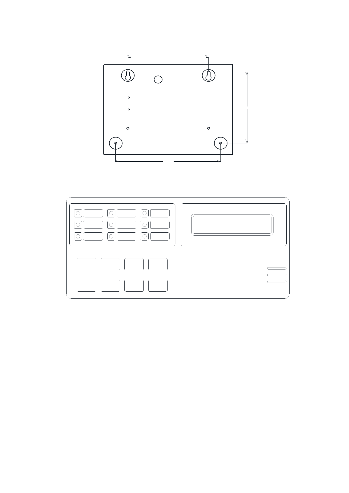
4.2 Installation of panel
Wall-mounted installation is adopted. For the installation dimensions, see Figure 3.2.
4.3 Wiring
After installation of panel, please refer to “Description of wiring terminal”to connect AC 220V Operate
Voltage, external equipment and panel. Connect wires according to the “Wiring requirements”in the Manual.
4.4 Panel inspection
After panel delivered, connect the Operate Voltage of the panel and check the panel functions, including:
(1) Check whether the AC power wire is connect and firm. In case of no mistake, connect the AC power wire,
measure the input voltage with the multi-meter, and then turn on the power switch;
(2) Check whether the panel indicator and LCD are functioning well. Check whether the c panel sounds
resonantly.
(3) With the panel during standby, check for power fault, check whether panel button works fine, and check
whether the equipment is normal.
4.5 Power on
Turn on the power switch or separately power on main power supply. Connect the battery (effective
DC12V/1.3AH battery 2) and then turn on the battery start switch. Then, the panel is restarting.
4.6 Commission
After wiring, carefully check it without mistake and then start up for commissioning. Debug it according to
the following steps:
(1) Turn on the power switch, and then the panel automatically detects the indicator, LCD and sound. After
self-test, the control module enters the normal monitoring state.
(2) Confirm that the detector is in the clean air and then debug it. For the specific operation method, see
“Chapter V System setup”and “Chapter VI Use and Operation”in the Manual.
Chapter V System setup
With regard to VI-6811 panel, we need go through several major settings, including device address and type,
system time, printer, relay output, sounder mode, etc. If needed, enter the relevant menu and directly set them. Enter
the system setup menu and enter the relevant password. All passwords shall be composed of the fixed buttons.
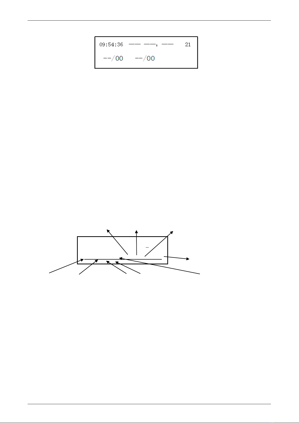
5.1 Description of main interface:
(1) Turn on the main power, the panel will go through self-test automatically. Afterwards, the panel will enter
into standby mode; if there is no any fire alarm or fault, the LCD screen will display the system’s running state
(EQUIPMENT RUNNING) and the current system time (9:24:32, June 8, 2013), as shown in figure 5.1:
Figure 5.1
(2) In case of fire alarm or fault occurred in standby mode, the screen will immediately display the detailed
information of the current event, as shown in Figure 5.2:
EQUIPMENT RUNNING
2013-06-08 09: 24: 32

VI-6811 Intelligent Fire Alarm Panel Installation and Operation Manual
Tianjin VSAIL Intelligent Fire Technology Co.,Ltd 6
System Clock Initial fire Time Devices
Fire Fault Time
Figure 5.2
(3) Meaning of display position in Figure 5.2:
System clock: Current time of the system.
Initial fire: In case of one or more fire events, the address number of initial fire will be displayed in this
position, (in case of no fire, “——” is displayed).
Time: System time of the initial fire occurred (in case of no fire, “——”is displayed).
Devices: Total quantity of device address registered in the panel.
Fire: “number on the right” refers to the total quantity of fire events, “number on the left” refers to the
address number of current alarming device(in case of no fire alarm, it displays “——/00”).
Fault: “number on the right” refers to the total quantity of fault information, “number on the left” refers to
the address number of current faulty detector (in case of no fault, it displays “——/00”).
5.2 Device address and type setup (refer to “5.4 Example”for operation)
Press “Configure”button on the keypad, enter the password according to the prompt (display “ENTER THE
PASSWORD”) on the interface). Continuously press “Search”button 4 times asPIN. Then, press“Configure”button
again. Then, enter DETECTOR SETUP MENU and display as shown in Figure 5.3:
6 Device OFF: 7 Device address, 8 OK (Enter)
9 Number of registered devices
1 Device ON: 2 Initial address 3 Last address 4 Device Type 5 Type confirmation (Enter)
Figure 5.3
Meaning of LCD display:
1 Device ON: Device range to be registered in the system.
2 Initial address: The first address of the device range to be registered.
3 Last address: The last address of the device range to be registered.
4 Device Type: One English letter stands for a certain type of device, refer to the list on the front of panel.
5 Confirmation: Press “Search” button to register the address and type, then “#” is displayed.
6 Device OFF: Tick off the identified device address from the registered list.
7 Device address: Enter the address number of device to be deleted.
8 OK: Press “Search” button to confirm the change, then “#” is displayed.
9 Number of registered devices: Total quantity of the devices registered in the system.
Function buttons: (refer to “5.4 Example”for operation)
“Shift” key: Move the cursor to the right (rotate right, press “Shift” key and move right).
DETECTOR SETUP MENU
ON:00-00 Y ←OFF 00← 21

VI-6811 Intelligent Fire Alarm Panel Installation and Operation Manual
Tianjin VSAIL Intelligent Fire Technology Co.,Ltd 7
“Search” key: With the cursor in the detector address selection bit, press “Search” key and add 1 (add the
number to reach 9, and then automatically reset to 0); with the cursor in the type selection bit, press “Search” key
to select the device type (the symbol meaning: Y refers to smoke detector, H refers to heat detector, F refers to
multi-sensor, M refers to manual call point, W refers to sounder beacon, I refers to monitor interface, O refers to
control interface; with the cursor in “←” position, press “Search” key to save the setting. After all, reset the panel.
*Note: Press “Reserved” button on the keypad to return to the homepage.
5.3 Time setup
Enter the menu bar or other menus, press “Configure” button on the keypad to see the display of “TIME
SETUP MENU” (As shown in Figure 5.4).
At first, press “Configure” button on the keypad, after see the window of “ENTER THE PASSWORD”, and
then press “Search” four times as password. Afterwards, press “Configure” again to move from the window of
“DETECTOR SETUP MENU” to the window of “TIME SETUP MENU” as shown in Figure 5.4
Figure 5.4
When enter the window of “TIME SETUP MENU”, press “Shift” button on the keypad to move the cursor
from left to right. When the cursor is at the setting position, press “Search” button to add one number to the date
and time. The system will automatically save the setting afterwards, then press “Reserved” button on the keypad
to return to the homepage.
5.4 Example
Example: Register address from #1 to #24, define as Smoke Detector. The configuring steps are shown as
below:
Step 1: Enter setting window (DETECTOR SETUP MENU)
Operation: Press “Configure” button and then press “Search” button four times as PIN in “ENTER THE
PASSWORD” window. Afterwards, enter the window of “DETECTOR SETUP MENU” as below.
Step 2: Set address #1 as starting point
Operation: Press “Shift” button to move cursor to the single digit of first number, and then press “Search”
button to add one number as “01”.
DETECTOR SETUP MENU
ON:00-00 ←OFF:00←00
DETECTOR SETUP MENU
ON:0■-00 ←OFF:00←00
TIME SETUP MENU
2013-06-08 09:18:32

VI-6811 Intelligent Fire Alarm Panel Installation and Operation Manual
Tianjin VSAIL Intelligent Fire Technology Co.,Ltd 8
Step 3: Set address #24 as last point
Operation: Press “Shift” button to move cursor to the tens digit of the second number, and then press “Search”
button to add one number until “2” appears. Then move cursor to the position of single digit and press “Search”
button until “4” appears. Then we have the last device as address #24, with the range of device address from #01 to
#24.
Select “2”position in “24”
Switch to the diagram of ones in the end bit
Display interface for finishing entering “24”
Step 4: Define detector type
Operation: Move cursor to the space at the right side to digit “4”, then press “Search” button to change the
symbol of device type, until letter “S” appears.
With regard to the symbol of device type, please refer to the label under the LCD screen as below.
S
Smoke Detector
H
Heat Detector
F
Multi-sensor Detector
M
Manual Call Point
W
Sounder Beacon
I
Monitor Interface
O
Control Interface
DETECTOR SETUP MENU
ON:01-■1 Y ←OFF:00←00
DETECTOR SETUP MENU
ON:01-2■←OFF:00←00
DETECTOR SETUP MENU
ON:01-24 ←OFF:00←00
DETECTOR SETUP MENU
ON:01-24 ■←OFF:00←00

VI-6811 Intelligent Fire Alarm Panel Installation and Operation Manual
Tianjin VSAIL Intelligent Fire Technology Co.,Ltd 9
Step5: Confirm and check
Operation: Move cursor to the arrow right after the symbol of device type, press “Search” until “#” appears
to save the above settings.
Reset the panel, refer to the steps above to enter “DETECTOR SETUP MENU”, move cursor to the last
number at the right end, then press “Search” to type in “24”, after all the LCD screen will be shown as below.
5.5 Relay Output Setup
There are two terminals of Relay Outputs on the Main Board described as Fire Output and Fault Output. And
this setting can change the mode of these outputs.
Press “Configure” button and then press “Search” button four times as PIN in “ENTER THE PASSWORD”
window. After entering the window of “DETECTOR SETUP MENU”, press “Configure” again down to the
window of “RELAY SETUP”, as shown in Figure 5.5.
Figure 5.5
Then press “Configure” on the keypad to switch between the “OFF” and “ON”, afterwards press “Reserved”
button to return to the homepage, and the setting will be saved automatically.
OFF Mode (as shown above): Any fire alarm will trigger the Fire Output, and any fault will trigger the Fault
Output.
ON Mode (as shown below): Any initial fire alarm occurred, the Fire Output will be triggered at first. When
second fire alarm reported, the Fault Alarm will be triggered as another Fire Output. And any fault will not trigger
the Fault Output.
5.6 Sounder Output Setup
DETECTOR SETUP MENU
ON:01-24 S# OFF:00←
DETECTOR SETUP MENU
ON:01-24 ←OFF:00← 24
RELAY SETUP: OFF
RELAY SETUP: ON

VI-6811 Intelligent Fire Alarm Panel Installation and Operation Manual
Tianjin VSAIL Intelligent Fire Technology Co.,Ltd 10
There is one conventional sounder circuit on the panel. The Sounder Output on the Main Board can be used
to connect with conventional sounder (reminder: EOL resistor 2K). And this setting can change the mode of
sounder output.
Press “Configure” button and then press “Search” button four times as PIN in “ENTER THE PASSWORD”
window. After entering the window of “DETECTOR SETUP MENU”, press “Configure” again down to the
window of “SOUND ALARM”, as shown in Figure 5.6.
Figure 5.6
Press “Shift” button to move cursor to the right of “SOUND ALARM”. Then press “Configure” on the
keypad to switch between the “OFF” and “ON”, afterwards press “Reserved” button to return to the homepage,
and the setting will be saved automatically.
Alarm Mode (as shown above): When initial fire alarm occurred, the Sounder Output will be triggered
immediately and conventional sounders are activated.
Pre-alarm Mode (as shown below): Any initial fire alarm occurred, the Sounder Output will not be triggered.
If there is second fire alarm occurred, the Sounder Output will be triggered and conventional sounders are
activated.
Chapter VI Use and Operation
6.1 System status
After starting up, the system running LCD displays the system time, as shown in Figure 6.1:
Figure 6.1
The top row displays the device state (normal running).
The bottom displays the system time.
In case of fire alarm or device fault, the system LCD displays as Figure 6.2
EQUIPMENT RUNNING
2013-06-08 09: 24: 32
PRINTER SETUP: ON
SOUND ALARM: OFF
PRINTER SETUP: ON
SOUND ALARM: ON

VI-6811 Intelligent Fire Alarm Panel Installation and Operation Manual
Tianjin VSAIL Intelligent Fire Technology Co.,Ltd 11
System time First fire First fire time Number of online detectors
Fire alarm/total number Fault/total number
Figure 6.2
In the above figure: 02 means the detector with 02 address alarms for the first time, “04/01”in the bottom
row means that address #04 device is faulty.
6.2 Self-test
Press the orange button “Test” on the front keypad, then press “Search” button four times as PIN in “ENTER
THE PASSWORD” window. When the PIN is correct, the system go through self-test automatically. The panel will
restart, buzzer sounds, all the indicators will be blinking, and the LCD screen displays as below.
6.3 Reset:
Press the “Test” button on the keypad, then press “Mute” button four times as PIN in “ENTER THE
PASSWORD” window. When the PIN is correct, the panel will restart automatically.
6.4 Mute:
During Fire or Fault status, the buzzer inside the panel will sound alarm. The “Mute” button on the keypad can
be used to silence buzzer.
6.5 Message view of Fire and Fault
When Fire or Fault occurred, the system enter into the message window automatically. Press “Shift” button to
switch the window among FIRE, FAIL and SUM. Press “Reserved” button to quit the window. If there is no
operation within 30s, the system will automatically return to the homepage.
System time First fire First fire time Number of online detectors
Fire alarm/total number Type Time
Figure 6.3
10/03 S means that the total number of fire alarms is 03. The information checked is No. 10 detection point.
The fire alarm is displayed by S smoke detector.
6.6 Message of initial fire alarm
In the window of Fire and Fault message, the message of initial fire is indicated at the top, including device
address and time of initial fire alarm.
EQUIPMENT SELF-CHECK
*****************
09:54:36 02 09: 54 23
0 2 / 01 04/01

VI-6811 Intelligent Fire Alarm Panel Installation and Operation Manual
Tianjin VSAIL Intelligent Fire Technology Co.,Ltd 12
System time First fire First fire time Number of online detectors
Fire alarm/total number Fault/total number
Figure 6.4
6.7 Fault of open-circuit
If there is open-circuit occurred in the detection loop, fault message will be reported to the panel within 60s.
Then please check with the quantity and address of faulty devices so as to identify the location of open-circuit.
6.8 Sounder
In case of fire alarm, the conventional sounders fromSounder Output will be activated automatically, and press
“Sounder” button on the keypad to silence the sounders. If there is no fire alarm, press “Sounder” button to activate
the conventional sounders manually, and press “Search” button four times as PIN in the window of “ENTER THE
PASSWORD”, afterwards, press “Sounder” button again to stop.
6.9 History log
Press “Search” + “Mute” buttons on the keypad, and then press “Mute” three times as PIN in the window of
“ENTER THE PASSWORD”. After that, enter into the window of History log as below.
In order to view different records, press “Search” button to move forward and “Shift” button to move
backward.
The screen will display the type and time of event. Please check with the symbol of event type as below.
1. “FIRE” stands for the records of fire alarm occurred.
2. “FAIL” stands for the records of fault info.
3. “RESET” stands for the records of system reset by press “Reset” button.
4. “OPEN” stands for the records of restart the panel.
Chapter VII Trouble Shooting
Table 7-1: Trouble Shooting
Problem
Reason
Solution
Fault on Sounder Output
1. The polarity is connected reversely
or the wire is connected wrongly
2. The EOL resistor is wrong
3. The panel is damaged.
1. Correct the wire.
2. Change with correct terminal resistance.
3. Contact the manufacturer.
EQUIPMENT RUNNING
****
NUMBER: ** SUM:**
06-06 11:49 OPEN

VI-6811 Intelligent Fire Alarm Panel Installation and Operation Manual
Tianjin VSAIL Intelligent Fire Technology Co.,Ltd 13
No display on LCD Screen or
black screen
1. The connection of the display board is
loose.
2. CPU board is loose or is in wrong
position.
3. Other causes.
1.Insert the plug tightly
2.Insert the CPU board tightly
3.Contact the manufacturer.
The probe reports the fault
1.The terminal wiring is wrong.
2. The module is connected reversely.
3. The probe is dirty or damaged.
4. The Operate Voltage is not normal, the
line is too long, the line diameter is small,
which make that the terminal voltage is
too small.
5. Strongly disturbed.
1. Check the loop line.
2. Check whether the module is connected
reversely.
3. Clean or replace the probe.
4. Find the cause for low voltage and increase
the terminal voltage.
5. Eliminate the interference (pass the pipe or
arrange wires again)
Chapter VIII Notes
The panel isthe precise electronic product, and needsto bemanaged bythe special person. People areforbidden
to randomly touch the panel.
The user shall carefully keep the working record. In case of alarm, press the “Mute”key on the panel, rapidly
confirm the fire and then handle with discretion. Keep the records, turn off the alarmed detector or module and
inform the company’s customer service center of repair.
Notice: When the main Operate Voltage is not connected but only the standby Operate Voltage is connected,
the standby Operate Voltage is consumed for a long time until the battery is used up. After the battery is discharged,
it shall be charged timely. Or else, the battery may be damaged. If it is not used for a long time, the battery wire
shall be disconnected. In order to lengthen the service life of the battery, when the battery is placed for more than 3
months, it shall be charged.
The company is responsible for warranty of the panel. In case of any problem, please timely contact our
customer service center. The user is forbidden to dismantle or repair the panel. Or else, the user shall suffer the
consequences.
Attached: For the installation method of printer housing, please refer to (Figure 8.1) assembly drawing
for installation. Itis fixed with M3 screws. When the printerwire and panel board J2 plug are connected, the
insertion direction of terminal shall be consistent with the silkscreen direction on the circuit board.
Chapter IX Transportation and Storage
9.1 Package and transportation
The panel is packaged with the damping, moisture-proof and compression-resistant materials. The panel is
transported with the common transportation tools. Besides, the panel shall not be exposed in the rain and snow
and shall not be collided with machines. The case shall not be placed reversely.
9.2 Storage
Before installation, the panel shall be stored in the warehouse and shall be at least 1m away from the walls.
The warehouse shall keep dry and ventilated and be free of acid and alkali and other corrosive gases. The panel
shall not be strongly vibrated.

Any quality problem may choose any of the following ways to contact us, we will wholeheartedly for your
service.
Company name:Tianjin VSAIL Intelligent Fire Technology Co.,Ltd
Company address:No.401, Building 6, No.1 Xinxing Roard, Wuqing Development Zone, Tianjin, 301700, China
Website:www.vsailglobal.com
Manual No.: VSL2.900.020AS
Table of contents
Popular Fire Alarm manuals by other brands

AJAX
AJAX ManualCallPoint Jeweller user manual

Secutron
Secutron MRM-800 Series quick start guide

Mircom
Mircom flexnet Configurator Guide

Silent Call Communications
Silent Call Communications FA41-MC Installation and operating instructions

Global
Global JUNO-NET Operation & maintenance manual

Panasonic
Panasonic EBL128 4550 overview

Nittan
Nittan NHD-G series instruction manual

Secutron
Secutron MR-2312-AT installation manual

Mircom
Mircom FleX-Net BBX-1024DS Application guide

Notifier
Notifier NFS-640 Programming manual

Notifier
Notifier AFC-600 operating manual

olympia electronics
olympia electronics BSR-2104/MAR Operation and installation manual