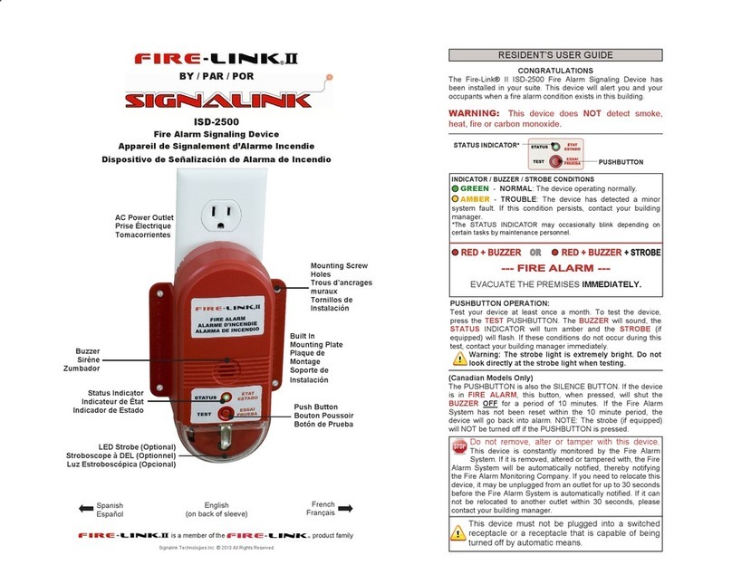
Signalink FIRE-LINK II User manual

SignalinkTechnologies Inc.
14-2550 Acland Road, Kelowna BC, Canada, V1X7L4 077.0061 Rev 1, Aug 2011
Technical Support:
(888)765 7514
www.signalink.com
©2011 SignalinkTechnologies: Fire-LinkQuick-StartGuide ©2011 SignalinkTechnologies: Fire-LinkQuick-StartGuide
TPC-101
3-Phase Coupler
1, 2, or3persystem
(oneforeach
transformer)
QUICK-STARTGUIDE
INSTALLATIONESSENTIALS
CHECK YOUHAVEEVERYTHINGYOUNEED
NMC-101
Panel
1persystem
(Connectsto
existing FireAlarm
ControlPanel)
CHK-400
Choke
1persystem
(provides filtered
powertoNMC)
Laptop SSC
software
OntheCD shipped
witheverysystem
Laptop
You will needto
providealaptop.It
makes thejob much
faster
USB-Serial
Adapter Cable
Ifyourlaptop hasno
DB9serial port,you
will needaUSB-
serialadapter
Instruction
Manuals
areprovidedin
hard-copyand on
theCD sentwith
everysystem
Barcode
scanner:
Makes
lifemucheasier!
Page 1
ISD2501UW or ISD-2501UWS
Hornonlyor
Horn&Strobe
In-SuiteDevice (ISD)
1persuiteorbedroom,
oras perAHJ’sinstructions
Beforemakingasale,aSiteSurveyshouldbewrittenup afterinspecting thebuilding,and
submittedtoSignalinkTechnicalSupport.Anapprovedsurveyensures thatyour
installationwill befast and easy. Downloadfromourwebsite www.signalink.com
Fire-Linkisrelativelysimpletoinstall.Nevertheless,itisasystemand theinstallerneedstobe
trained.Inadequatetrainingleadstobadinstallationsand unsatisfiedcustomers:
Signalinkhas anon-linetraining and certification process on itswebsite,and isavailable
byemail.Pleasetakethetimetogettrained! Itonlytakes ashort while,willgiveyou
satisfiedcustomers,andwill saveyourorganizationtimeand money
SubmitSiteSurveysto: support@signalink.com Fax (250)491 3895
1
2
DealerKitincludesthese items
Beforegoing on-site:READ THISSYSTEM GUIDEFIRST!
Makesureyouhavetheappropriate training, and asitesurvey
Page 4
Prepare the Job File
CreatealistoftheISD’sand theirlocation—using alaptop
· Laptop and barcodescanner:Pre-loadtheSignalinkSystemConfigurator(SSC)
softwareprovidedonCD witheachsystem.RunSSC onthelaptop.Note:the
laptopwithbarcodescannerisnotessential,butishighlyrecommendedforspeed
ofinstallation,accuracyofinformation,andtohaveacomputerrecordofthejob
details.ABarcodeScannerand theCableAdapterareavailableintheDEALERKIT
· ScantheVIDnumberof eachISD andwriteitsintendedlocation ontheback label
· Enterthejob file,and setup thesystem:Consult 077.0045NMCProgramming Manual. Ifusing
alaptop,alsoconsult 077.0046:SignalinkSystemConfiguratorUser’sManual
Install the ISDs ineachsuite (See ISD Installation Q/SGuide)
DO
· AnchoreachISD using4
screws,ifpermitted
· Check foraoneflashper
second blinkingyellow
STATUSlightafterplugging
theISD intoareceptacle
· Press theTESTbutton after
pluggingtheISD intoa
receptacletotestthealarm
· Instructthetenantwhat the
device isandwhatitdoes
DoNOT:
· Place theISD overa
source ofheat suchas a
base boardheaterorhot air
register
· Place theISD indirect sunlight
· InstalltheISD intoaswitched
receptacle
· Forgettoleavebehindthe
resident’sinstruction “sleeve” to
advise theresidentwhat the
device isandwhatitdoes
· Introduceyourself: andtelltheresident whatyou aredoing
· SelectasuitableACoutletforbestaudibility,plug itin.CAUTION!
DONOTPLUGITINTOANACOUTLETTHATCANBE SWITCHED
OFF!FIXTHE ACRECEPTACLE IFNEEDED FOR GOODCONTACT
· Ifno-oneissleeping,press TESTand letthemhearthealarm
· Explainthelight will gogreenwhenthesystemisrunning
Enroll the ISDs and Test& VerifySystemOperation
· Ensurethesystemtimeand dateisset correctly, and clearallthelogfiles
· Consult 077.0045NMCProgrammingManual forEnrolmentinstructions.Theactofenrolling
theISDsisfullyautomatic,and allowstheNMCtoverifythatallISDsarecommunicating
properly,and thattheyhavegoodACpower,agoodbattery,and thatthebuzzerisworking
properly(and strobeif fitted).
· Test thecompletesystemusing the ISD TEST ALL function
· Ifusingthelaptop,createandsavea CommissioningReport
Explainthe Systemto the Building Manager
· Givehimorherdocument 077.0025:Building Manager’sGuide. Explainhowtosilence
troublesand howtoresolvelocaltroublescausedbyresidents’behavior
· Explainthetroublelog “LOG”and“VIEW” features:tosee whichsuiteisintrouble
TESTbutton
STATUSlight
BUZZER
6
7
8
9
NEEDHELP?CALLTECH SUPPORT (888)765 7514 support@signalink.com

SignalinkTechnologies Inc.
14-2550 Acland Road, Kelowna BC, Canada, V1X7L4 077.0061 Rev 1, Aug 2011
Technical Support:
(888)765 7514
www.signalink.com
©2011 SignalinkTechnologies: Fire-LinkQuick-StartGuide ©2011 SignalinkTechnologies: Fire-LinkQuick-StartGuide
DecideTheLocationOfSystemComponents:
Ofcourse,thismaybedoneprior toinstallation
Consult document077.0024:NMCandTPC Installation Guide
NMC:TheNMCneedstobewall-
mountedinasecurearea withthe
abilitytoconvenientlywiretothe
FACP,and nearthehouse panelif
possible.Theelectricalroomis
usuallyagood spot.Normallythe
electricalhouse panelistypically
20 feetorsofromtheTPC and
NMC.Themaximumdistance is200feet
Choke: Tobemountedinajunction boxnearorwiththeTPC
TPC: NormallytheTPCismountedinthesameroomas theNMC, and thenwired
totheappropriatepanel.If multipletransformersareinthesystem,eachneedsa
TPC
MultipleTPCsmustbemountedinthesameroom,within6feetofeach
other,and interconnected(see below)toensurethesignalsplitsevenly
toeachtransformer
EachISD isinstalledinthesuitetoprovidethedesiredNFPA72level(75dB
minimumatthepillow). Ofteninstalledinthemainbedroom
CAUTION!DONOTPLUGITINTOANACOUTLETTHATCANBE
SWITCHED OFF!
Electrical Wiring:
Aqualifiedelectricianneedstodo thiswork, including pulling thepermit
Consultdocument077.0024:NMC and TPCInstallation Guideor
document077.0050:TPCInstallation Guide(providedwitheachTPC)
Overview:Theelectricalwiringisstraightforward,buttoodetailedto
describeinthisQuick-StartGuide.Theelectricianmustbegivencopies
ofdocuments 077.0024and/or077.0050,whichcontainswiringdiagrams
and instructionsforvariousconfigurations,includingsingle-transformer
and multiple-transformerinstallations,as wellasthree-phaseandsingle-
phase center-tappedinstallations.(Thetwodocumentshavesimilar
electricalwiring contents,exceptthat077.0024 alsohas mounting
templates)
· NMCPower:NMCPowerisalwaysprovidedviatheChoke CHK-400
whichhas twopurposes—itfiltersthepowertotheNMCandit prevents
theNMCACsource fromaffectingthestrengthofthePowerlineCommunicationshigh-
frequencysignals
· TPC wiring:TheTPC isconnectedtotheNMCpowerterminalsand splitsthepowertothe
variousphases oftheAC powerdistribution system.Itsfunction istosplitthesignalsequallyto
eachphase
· MultipleTPCs: MultipleTPCs, ifrequired, areco-located, asabove. Theyareinterconnectedby
theorangewiretosplit thesignal equallytothetransformers
Field-wire the NMC to theFireAlarmControl Panel (FACP)
Consult document077.0048 NC FireAlarmWiring Guide
· NMCPower:NMCPowerIssuppliedviatheChoke, perstep4
· SafetyCode: DoNOTbundletheFACP low-voltagewiring withtheACwiring
· DetailedInstructions: Consult 077.0048NMCFireAlarm WiringGuide documentfordetailed
instructionsand diagrams
· TypicalBellCircuit Wiring: Typicalalarmpanelcontrolwiring uses asparefirealarmBell
OutputCircuitconnectedtotheNMCBellCircuit Input.ThisallowstheFACP toputtheNMC
intoAlarm mode.
· Typical“Trouble”wiring: TheNMC“Trouble”OutputisconnectedthroughanEnd-Of-Line
(EOL)resistortotheNMCBell CircuitOutput,sothatwhenaFire-Linktroubleisdetectedit
openstheEOLand causes a“Trouble”totheBell Circuiton theFACP
· WhenStrobes areused: AnFACP OutputCircuitisconnectedviaaSupervisedRelaytothe
NMCInputCircuit Zone#1.AnEOLresistorisfittedacross theNMCterminals.This
allowsthestrobestocontinueflashingevenwhentheFACP silences thealarm.Note:
alwaysuse relaycontactsforthispurpose—donotconnect theFACPdirectlytotheZone
circuits.
Page 2 Page 3
3
4
5
NEEDHELP?CALLTECH SUPPORT (888)7657514
NEEDHELP?CALLTECH SUPPORT (888)7657514
BELLCIRCUIT
CONNECTION
TROUBLE
CIRCUIT
ONLYREQUIRED WHEN
STROBES AREUSED
(RELAYKEEPS STROBES
ONUNTIL ALARMIS
RESET
Other Signalink Fire Alarm manuals
Popular Fire Alarm manuals by other brands
NAiS
NAiS EBL512 operating instructions
E2S
E2S D2xC2LD3 instruction manual
Cooper Notification
Cooper Notification RSS-24MCC installation instructions
Synaps
Synaps LF24W installation instructions

Kentec Electronics
Kentec Electronics Taktis Vision Installation and operation manual

FireClass
FireClass MCP200CS quick start guide

CWSI
CWSI CP-3000DA Operating and installation instruction manual
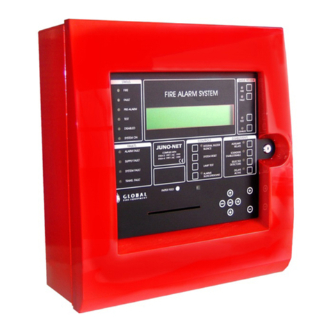
Global
Global JUNO-NET Operation & maintenance manual
Pyro-Chem
Pyro-Chem Kitchen Knight II Technical manual
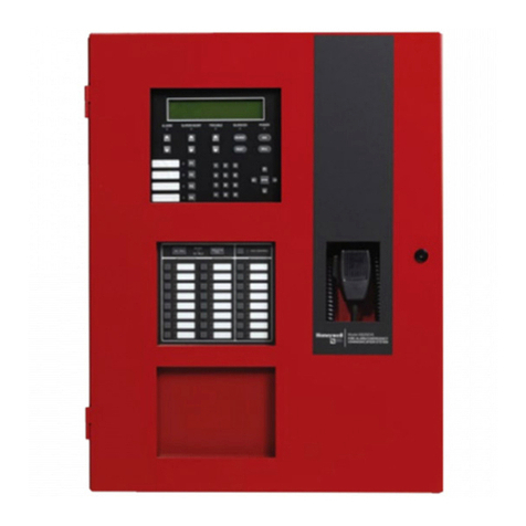
Honeywell
Honeywell Silent Knight 6820EVS Basic operating instructions

Simplex
Simplex 4010ES Operator's manual

INIM
INIM IRIS ID200 user guide
