1. INTRODUCTION
1.1 PRECAUTIONS, REQUIREMENTS, RECOMMENDATIONS
Read the documentation carefully, install and use the equipment according to the specifications, and follow all the safety regulations in order to
ensure proper and safe use of the device. Any use that is incompatible with these instructions can cause serious injuries. Restrict access by
unauthorized persons and train the operational personnel. The term operational personnel refers to people who are suitably trained and have
appropriate experience and knowledge of relevant norms, documentation and occupational health and safety regulations, and are authorized to
conduct the required work and can identify possible threats and avoid them. This operation and maintenance manual, which is delivered with
the device, includes detailed information on all possible configurations of the heaters, examples of their assembly, start, use, repair and
maintenance. To operate this device correctly, this manual includes instructions sufficient for qualified personnel. The documentation should be
placed close to the device for ease of access by the service team. The manufacturer reserves the right to introduce changes to the manual or
the specifications of the device, which may alter its operation, without prior notice. VTS POLSKA Sp. z o.o. shall not be held liable for current
maintenance, servicing, programming, damage caused by standstill of the device awaiting warranty service, any damage to customer’s
possessions other than the device, or faults resulting from the wrong assembly or use of the device.
1.2 TRANSPORT
Prior to the installing and taking the device out of the cardboard box, it is required to check whether the cardboard box has not been damaged
in any way and/or the adhesive tape (installed at the company) has not been broken off or cut. It is recommended to check whether the
device’s casing has not been damaged in transport. Should any of the above situation occur, please contact us through telephone or e-mail: Tel.
0
801
080
073,
email:
[email protected],
fax:
(+48)
12
2
96
50
75.
The device should be transported by two people. Use appropriate tools, when transporting the device, so as to avoid the damaging of goods and potential hazard to health.
1.3 INITIAL STEPS TAKEN BEFORE THE INSTALLATION
Record the serial number of the device in the warranty card, prior to the commencement of the installation process. It is required to properly
fill-in the warranty card, after the completion of the assembly. Prior to the commencing of any installation or maintenance work, it is required
to disconnect power supply and protect it against unintentional activation.
2. STRUCTURE, INTENDED USE, PRINCIPLE OF OPERATION
2.1 INTENDED USE
VOLCANO VR has been designed to ensure ease of use and optimum performance.
The device is available in fife versions:
VOLCANO VR Mini (10-68 MBH, 1236 CFM)
VOLCANO VR 1 (17-102 MBH, 3119 CFM)
VOLCANO VR 2 (27-170 MBH, 2855 CFM)
VOLCANO VR 3 (44-256 MBH, 3355 CFM)
VOLCANO VR-D (3826 CFM)
VOLCANO combines state-of-the-art technology, innovative design and high effectiveness. Unique technical solutions such as the design of the
heat exchanger, improved fan and increased range of air stream, allow the VOLCANO heater to achieve optimal heating power, perfect for the
size and type of room. APPLICATION: production halls, warehouses, wholesale outlets, sports facilities, greenhouses, supermarkets, church
buildings, farm buildings, workshops, health care facilities, pharmacies, hospitals. MAIN ADVANTAGES: high effectiveness, low maintenance
costs, full parameter control, easy and quick assembly.
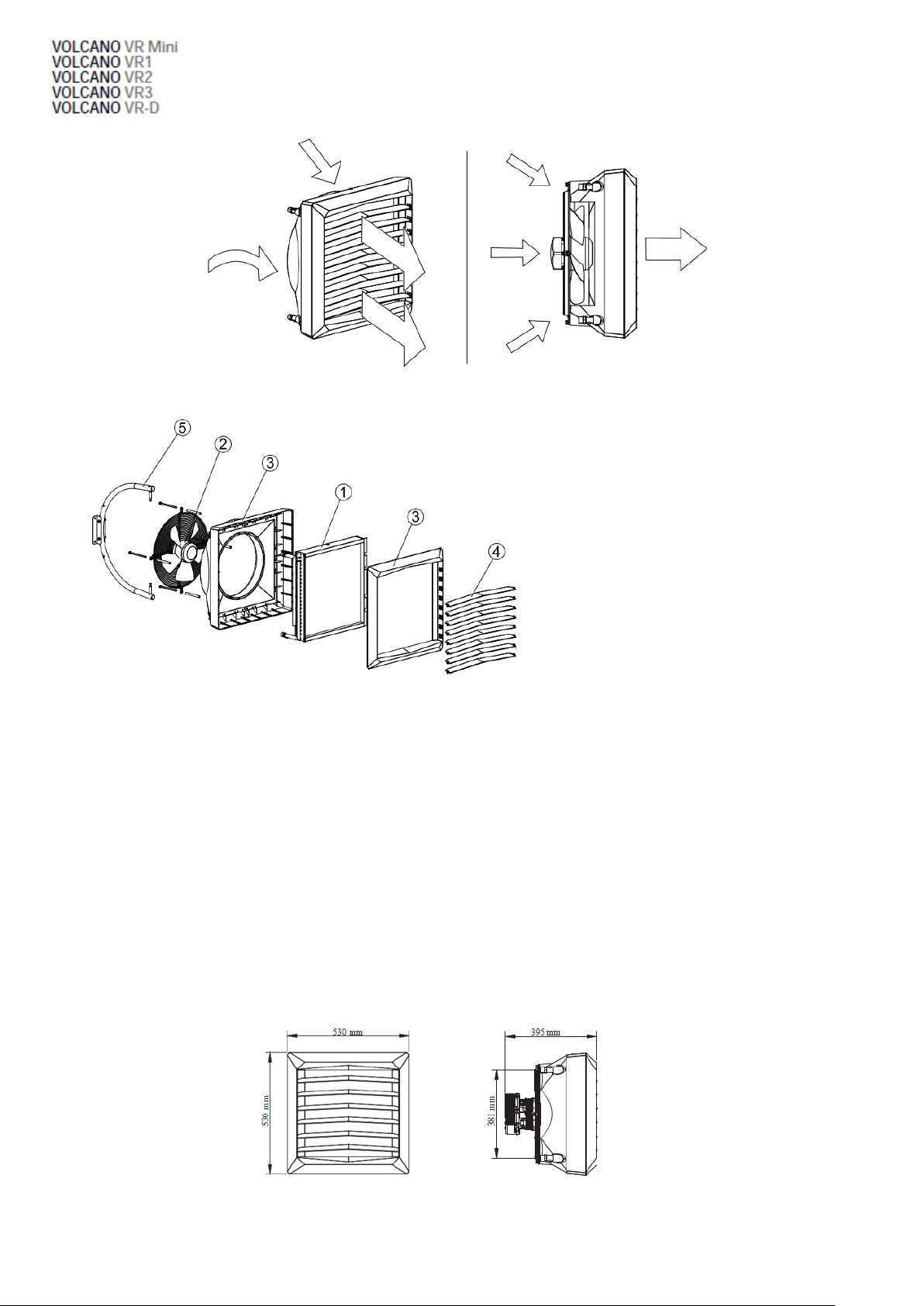
2.2 PRINCIPLE OF OPERATION
The heating medium (hot water) gives up heat to the heat exchanger using a highly developed heat exchanger, ensuring great heating power
(Volcano VR Mini –10-68 MBH, VR 1 –17-102 MBH, VR 2 –27-170 MBH, VR 3 –44-256 MBH). A highly effective axial fan (674-3355 m3/h)
draws air in from the room, pumps it through the heat exchanger and then sends it back into the room.
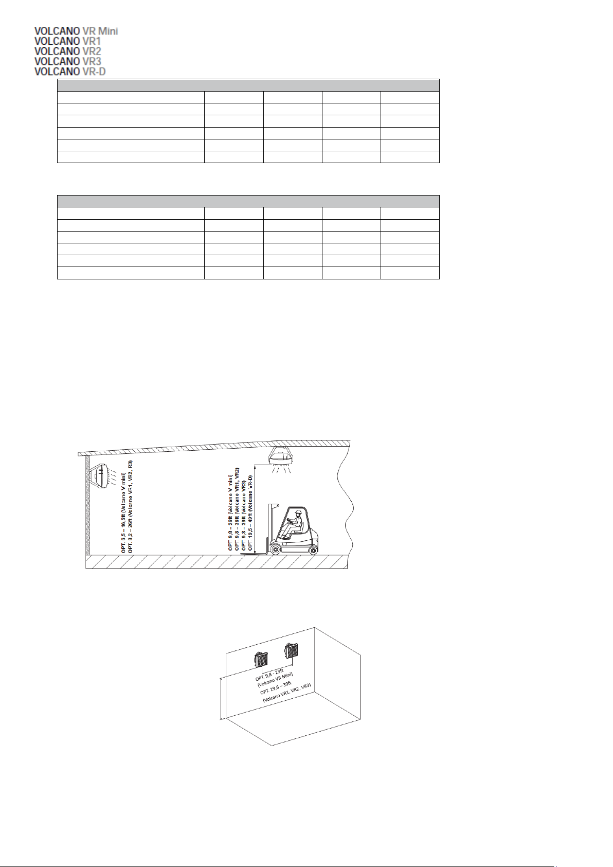
Volcano VR-D de-stratifies the heated air from the sub-ceiling zone to the above-ground zone. Hot air exhaust results in a leveling of the
temperature gradient in particular air layers and contributes to reducing the costs of heating by lowering the temperature in the ceiling zone,
thus limiting heat loss through the roof. The VOLCANO VR-D de-stratifier will be the most effective in combination with VR Mini, VR1, VR2 and
VR3 air heaters. Cooperation of both of these device types will allow for achieving optimal temperature comfort fast due to the support of the
heating system through more efficient distribution of hotair.