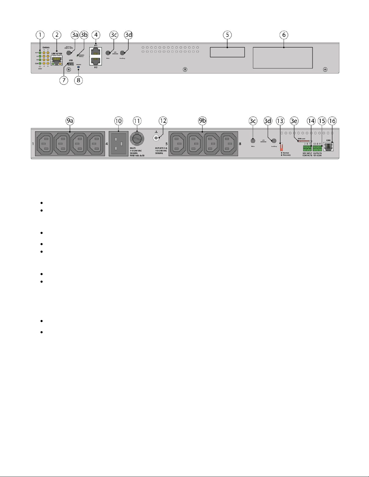
Vutlan VT608 User manual

VT608 / Switching PDU with 8 outlets
Visit our Online documentation for the latest information.
Documentation page: https://vutlan.atlassian.net/wiki/spaces/DEN/pages/2313617561
/VT608+Switching+PDU+with+8+outlets
Product page: https://vutlan.com/power-distribution-units/153-vt608-switched-ip-pdu.html
Function and purpose
The Switched Power Distribution Unit (PDU) is used for load management and allows to switch on/off or reboot up to 4 outlets.
It has a built-in temperature sensor, can connect x2 additional analog sensors, x2 dry contact inputs, x2 12V controlled
outputs for devices (e.g. alarm beacon or a relay contact) and a digital CAN port for connecting up to x20 sensors or
extensions.
There are built-in servers and agents like HTTP, HTTPS, SNMP v1, 2c, 3, SMTP, Radius, Syslog, FTP, DHCP, and Watchdog.
" " or " " can be integrated inside the system. Modems are purchased separately.VT700 / GSM modem VT760 / LTE modem
Physical Description
Front panel:

Back panel:
1. " " - green - indicates appliance statusACT / STATUS
"LEDs: " - status indicators for x2 12V 0.25A outputs at the back of the unit.E1, E2
The LED is ON (orange) - the output is ON (the initial state can be configured).
The LED is OFF (orange) - the output is OFF ((the initial state can be configured).
" " - green LED indicates CAN bus status.LED: CAN
The LED blinks slowly - nothing is connected
The LED blinks fast - configuration is in process
The LED glows constantly - connected to CAN devices
" » - red - indicates error and traffic.ERROR
the operating mode of the device: If everything is normal, the LED is extinguished, if not - there's a constant glow;
software update mode: switches at a rate of 2 times per second;
"OUTLETS 1 - 8" - orange - indicate outlet status.
2. " " - Ethernet 10/100 Base-T port, provides an Ethernet connection. Read more in this section "LAN port LAN, GSM, LTE,
".RADIUS, DNS, SSL, VPN
" " - orange LED for Ethernet port. Shows network traffic.Orange LED
" " - green LED for Ethernet port. Shows network traffic. Flashes green when the system starts up. Shows the Green LED
connection state (constant green light - the connection is established, blinking green - the connection attempt).
3. This is a slot for " " or " ". Modems are purchased separately.VT700 / GSM modem VT760 / LTE modem
3a. " " - connector, used when GSM modem is installed inside of the appliance to connect GSM ANTENNA GSM or GPS
antenna. (GSM modem is ordered separately). Or it is used for connecting a GPS antenna to " " for VT760 / LTE modem
correct time detection. GPS antenna is not soled together with the modem.
3b. " " - displays modems status. Blinking = working.Status
3c. " " - Connector, used when the LTE modem is installed inside of the appliance to connect LTE main Main antenna
antenna. (The main antenna is supplied together with the modem).
3d. " " - Connector, used when the modem is installed inside of the appliance to connect LTE auxiliary antenna. Auxiliary
The additional antenna helps to strengthen the signal level. (Auxiliary LTE antenna and antenna output are ordered
separately from the modem).
3e. - SIM card slot with an injector."SIM card"
4. " .. " - x2 RJ12 analog sensor inputs with auto-sensing. Read instructions at " ", "A1 A2 Analog sensors connection Sensor

4. " .. " - x2 RJ12 analog sensor inputs with auto-sensing. Read instructions at " ", "A1 A2 Analog sensors connection Sensor
".configuration
5. " " - A place for a sticker, can be used by a user to place an identifier of the system (for example, an IP Sticker space
address).
6. " " - Displays article number of the monitoring unit.Logo sticker
7. " " - type miniAB USB-port 2.0. USB ports are needed for USB camera recording, USB Flash for system logs, and system USB
restore. Read instructions at " ", " ", "Connecting USB camera USB camera settings. How to save a video Saving system logs on
", " ".USB flash drive USB upgrade or restore of default settings
8. " " - the button restarts the appliance. Hold the button for 2 seconds and then let go, the system will restart.RESTART
9. " ", " " - x8 power outlets C13 110-240VAC 50/60Hz. Read instructions at: "Outlets 1-4 5-8 A relay switching (NC NO) /
".Outlets switching
10. " " - 110-240VAC 50/60HzINLET
11. " " - Inlet fuse 16A 6x30mmFUSE
12. " " - Chassis grounding, M4 thread. Enhances the immunity of the equipment against conducted and radiated RF
disturbances. Please contact a professional electrician before connecting it.
13. " " - A switch controlling the operating mode of the systemDip switch
Operating mode: Up >> Off - the system should be always switched to this model.
Recovery mode: Down >> On - use this option only in case you need to recover manufacturing settings. Read
instructions at: " ".Restore of appliance
14. " " - x2 digital inputs (Type IN). Read instructions at " ", "DRY CONTACT INPUTS 1...2 Connecting dry contacts Dry contacts
".settings
15. - 12V 0.25A (for each output) terminals outputs (electronic relay). Read instructions at ""OUTPUT 12V 0.25A" Connecting
".12V devices to 12V outputs
16. " " - digital connector RJ12 for the connection of CAN sensors and CAN extensions on a CAN bus, with auto-sensing. CAN
Modules can be chain together. Read instructions at " ", " ".CAN devises connection Setting up CAN
Connection overview diagram

Dimensions

Inventory
Make sure that the contents of the delivery meet the following configuration. Report a missing or damaged component to your
supplier. If damage occurred during transportation, contact the appropriate delivery service.
Package content Description
1 Switchable PDU unit VT608.
2EU Schuko C13 0.75 230V 10A cable.мм2

3 RJ-45 1m patch cable
4 Self-adhesive rubber foot - 4 pcs
5 Terminal plug 3 pins, 3.81 mm - 1 pcs
6 Terminal plug 3 pins, 3.5 mm - 1 pcs
7 Configuration manual

8 Warranty card
Transparent plastic bag 70x125mm:
Package content Description
1 19" rack brackets - 2 pcs
2
M3 x 8mm Phillips flat-head screws - x6 pcs
(transparent plastic bag 42x70mm)
Technical specifications
Device description VT604 VT608
Description: Switchable Switchable
Device management: Web, SNMP, manual using SMS, 4G LTE Yes Yes
Sensor access: Three-level by login Yes Yes
Interface and supported protocols VT604 VT608
Interface: Any browser Yes Yes
LAN: Ethernet 10/100 Mbit Yes Yes
Network protocols: DHCP, HTTP, HTTPS, SNMP, SMTP, SSL, FTP, Syslog, RADIUS Yes Yes
OS: Linux 3.10 3.10

Memory: 64Mb 64Mb
CPU Speed: 300 MHz 300 MHz
Notifications: FTP, Syslog, SMTP, SNMP, SMS (Modem ordered separately) Yes Yes
Ping: Built-in pinging Yes Yes
LEDs: System status, CAN, 12V outputs E1 and E2, System Error 4 8
LEDs: Orange for relays 4 8
Clock: Built-in clock with time synchronization Yes Yes
Timer: Built-in watchdog Yes Yes
Power VT604 VT608
Power supply: 110-240V
50-60 Hz
110-240V
50-60 Hz
Input: C14 10A C20 16A
Fuse: 10A 16A
Outputs: 4 8
Power consumption: 10W
Total power load: 2.4 kW
Power measurement: No No
Outputs: Bistable relays with indication on the front panel 4 8
Inputs / Outputs VT604 VT608
Mini USB AB: USB 2.0 HS Yes Yes
Sensors: Analog sensors RJ12 2 2
CAN bus: RJ12 for connecting up to 12-20 CAN devices per bus. See "CAN
".devises connection
11
Bistable relays: with indication on the front panel x4
Max 10A
x8
Max 10A
Sockets: 4
IEC 320 C13
8
IEC 320 C13
External memory VT604 VT608
USB flash card slot: Yes Yes
Scalability (units are ordered separately) VT604 VT608
Extension unit: Allows increasing the number of sensors in the system. CAN CAN
Modem: Internal GSM, LTE GSM, LTE

1.
2.
3.
Environment VT604 VT608
Operating temperature: 0 to 60 °C Yes Yes
Storage temperature: –25 to 85 °C Yes Yes
Operating humidity: 0 to 90 %, non-condensing Yes Yes
Storage humidity: 0 to 95 %, non-condensing Yes Yes
Options VT604 VT608
Installation: 19” 19”
Dimensions (L x W x H) in mm: 440*44*80 440*44*80
Weight: 1,3 kg 1,5 kg
Installing a modem
Please refer to the following articles:
" " or " " can be integrated inside the system. Modems are purchased separately.VT700 / GSM modem VT760 / LTE modem
Installing the device into a 19" rack
Use x3 pcs of supplied screws (M3 6mm) for each bracket to fix it on each side of the enclosure as shown in the picture below.
The screws and brackets are supplied with the unit.
Device configuration
Initial Configuration (web interface)
Configuring (web interface)
Upgrade and restore options

Developer notes: Model v3.1, Published 12thMay2021
This manual suits for next models
1
Table of contents
Popular Power Distribution Unit manuals by other brands

Alpha Technologies
Alpha Technologies Cordex HP 48 1.2kW Technical guide

Oh!FX
Oh!FX TC-107 Quick user guide

Enlogic
Enlogic EN2101 Installation and operation manual

Power Innovations
Power Innovations MPDU user manual

Jedia
Jedia JPD-322AU operating instructions

EV-OPTIMIZER
EV-OPTIMIZER High Current installation manual