VWR Gel Imager Guide

Gel Imager and Gel Imager Plus
Installation and User Instructions
81-0317-01 Rev A
Gel Imager

Gel Imagers 2
System Introduction
Gel Imagers and Gel Imagers Plus
The Gel Imagers enables simple documentation of fluorescent and non-fluorescent gels,
membranes, blots, film plates and assays with the ability to save images to a USB storage device for later
quantitative analysis or enhancement for publication.
Images are saved in 8-bit TIFF or JPEG formats allowing the images to be read by most PC or MAC
programs. The Gel Imager system is a cost effective solution for archiving quality images in a compact
standalone package. No computer is required.
The models comes in two configurations:
Gel Imager Plus, a high resolution 1.3 megapixel camera, 8-48mm zoom lens or
Gel Imager - a 0.3 megapixel camera and a 5.7-34.2mm zoom lens.
System Components
Components
Refer to the packing slip and pictured components for parts included with the system.
Gel Imager Plus
8” LCD touch screen
with tilt capability
White light and darkroom
p
ower switches
Wide access
door
USB drive
Filter tray (located under the
camera) with EtBr filter
Main s
y
stem
p
ower switch
View port
Transilluminator
Camera and zoom Lens
Stylus pen
Side access door (Gel
Imager Plus models only)

Gel Imagers 3
System Specifications
Configurations
Part No. Description
89131-380 Gel Imager, 0.3 Camera, 20 x 20cm Transilluminator, 302nm UV, 115V
89131-382 Gel Imager, 0.3 Camera, 20 x 20cm Transilluminator, 302nm UV, 230V
89131-384 Gel Imager, 0.3 Camera, 21 x 26cm Transilluminator, 302nm UV, 115V
89131-386 Gel Imager, 0.3 Camera, 21 x 26cm Transilluminator, 302nm UV, 230V
89131-388 Gel Imager, 0.3 Camera, 20 x 20cm Transilluminator, 302/365nm UV, 115V
89131-390 Gel Imager, 0.3 Camera, 20 x 20cm Transilluminator, 302/365nm UV, 230V
89131-392 Gel Imager, 0.3 Camera, 21 x 26cm Transilluminator, 302/365nm UV, 115V
89131-394 Gel Imager, 0.3 Camera, 21 x 26cm Transilluminator, 302/365nm UV, 230V
89131-396 Gel Imager Plus, 1.3 Camera, 20 x 20cm Transilluminator, 302nm UV, 115V
89131-398 Gel Imager Plus, 1.3 Camera, 20 x 20cm Transilluminator, 302nm UV, 230V
89131-400 Gel Imager Plus, 1.3 Camera, 21 x 26cm Transilluminator, 302nm UV, 115V
89131-402 Gel Imager Plus, 1.3 Camera, 21 x 26cm Transilluminator, 302nm UV, 230V
89131-404 Gel Imager Plus, 1.3 Camera, 20 x 20cm Transilluminator, 302/365nm UV, 115V
89131-406 Gel Imager Plus, 1.3 Camera, 20 x 20cm Transilluminator, 302/365nm UV, 230V
89131-408 Gel Imager Plus, 1.3 Camera, 21 x 26cm Transilluminator, 302/365nm UV, 115V
89131-410 Gel Imager Plus, 1.3 Camera, 21 x 26cm Transilluminator, 302/365nm UV, 230V
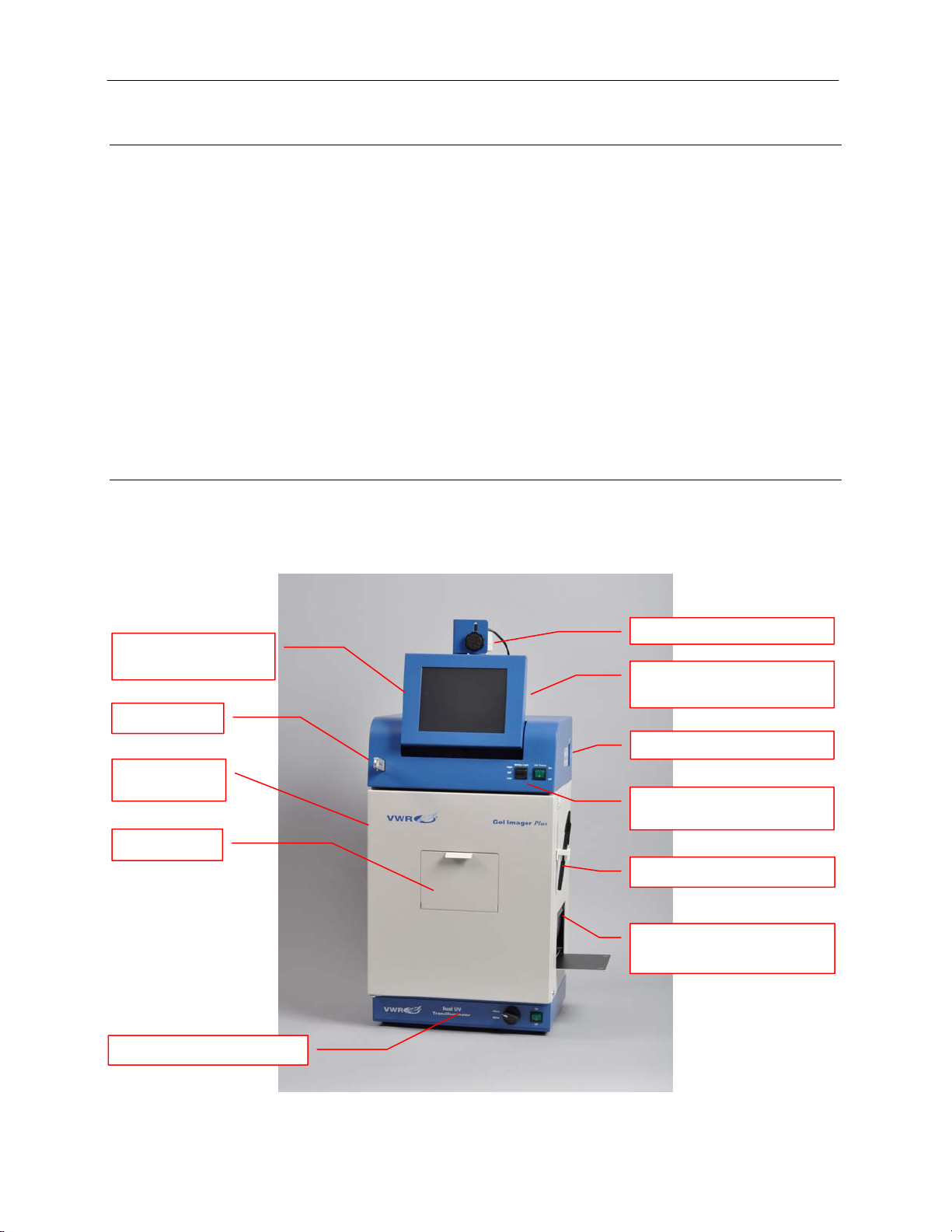
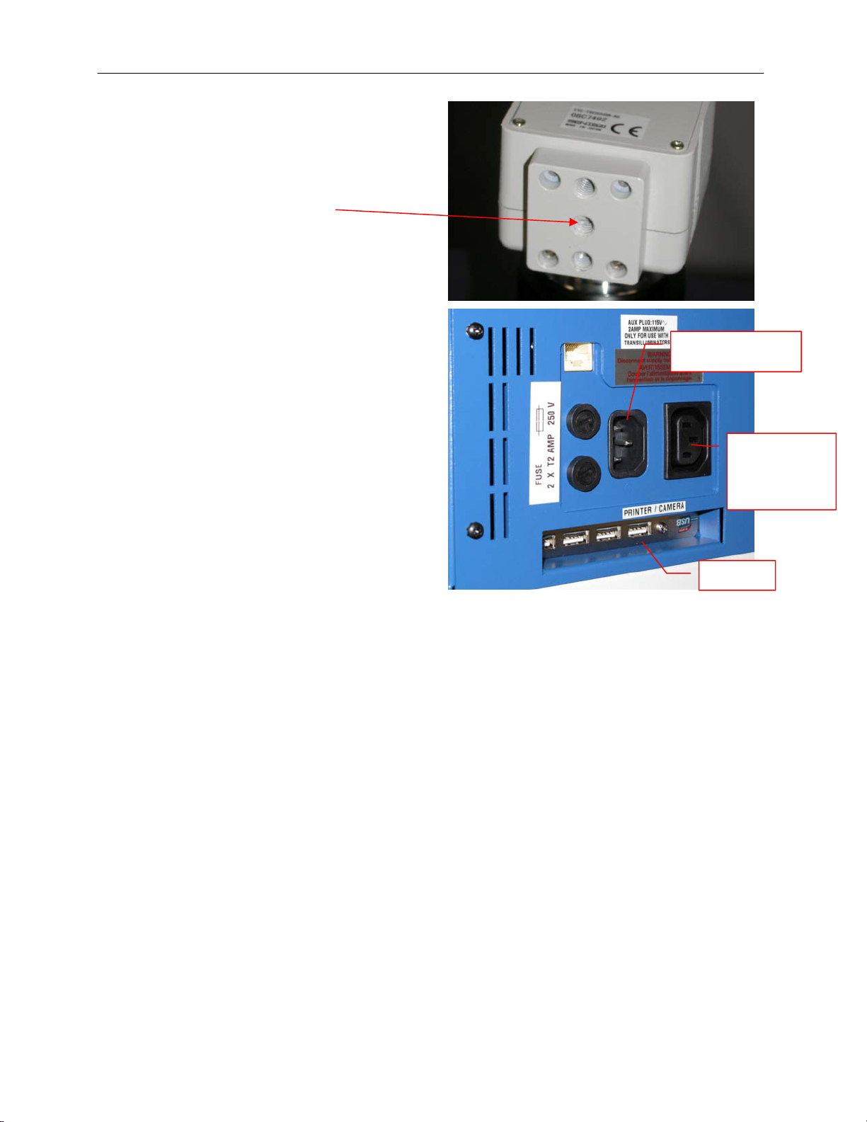
Camera
System will be configured with one of the two camera
options: 1.3mpx (high resolution) or 0.3mpx .
Both cameras use a USB 2.0 PC connection. All camera
settings are factory pre-set for optimum performance when
viewing gels, films, or membranes under low light level
conditions. UVP Technical Support should be contacted
before making any adjustments to the camera settings.
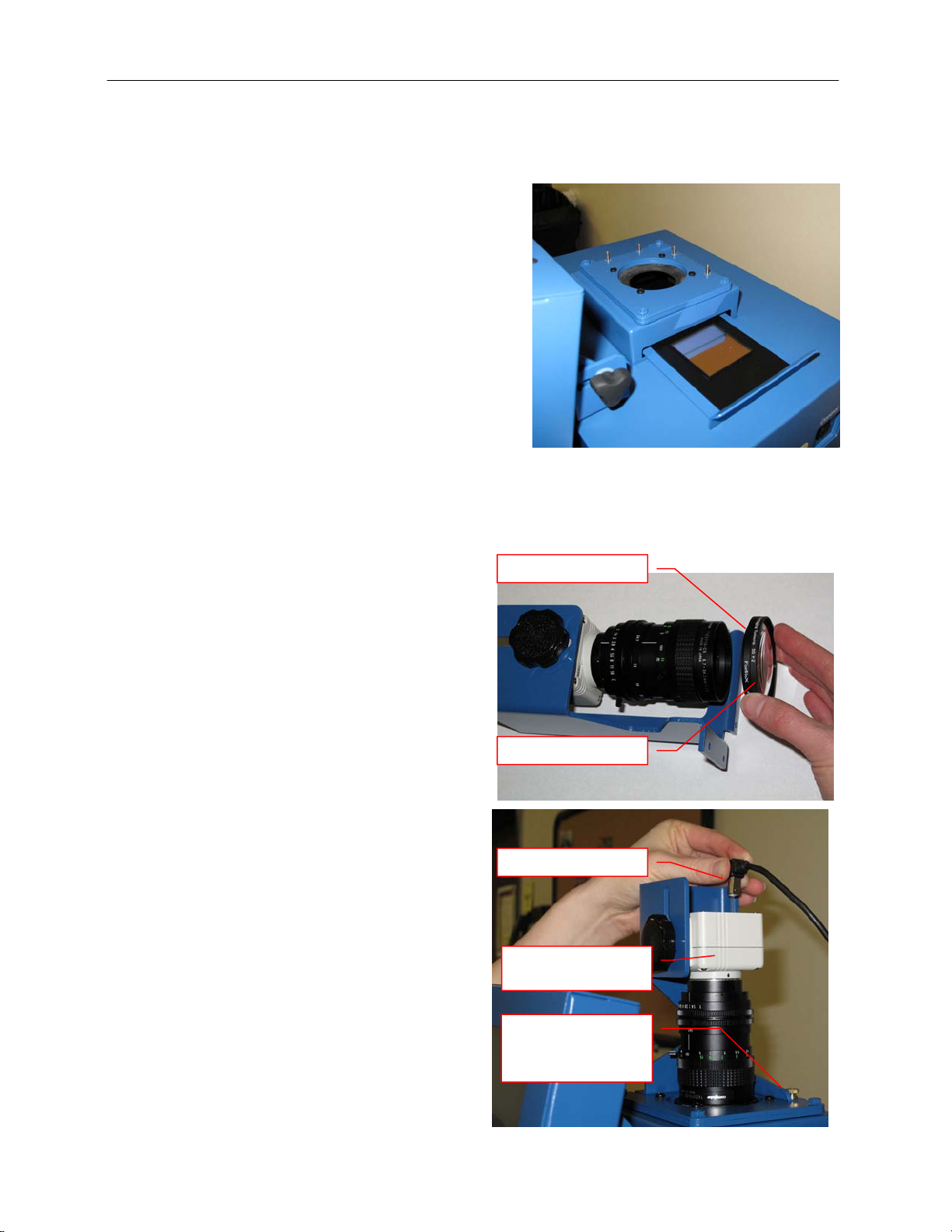
Lens
The Gel Imager Plus with the 1.3mpx camera is equipped
with an 8-48mm zoom lens fitted with a close-up diopter and
step-up ring. The camera can then be held in a fixed
position. The diopter is for focusing on objects at the focus
length of the Gel Imager.
The Gel Imager with the 0.3mpx camera is equipped with a
5.7-34.2mm zoom lens fitted with a close-up diopter and
step-up ring. The camera can then be held in a fixed
position. The diopter is for focusing on objects at the focus

Gel Imagers 4
length of the Gel Imager.
Processor
Internal Storage: 75GB or more
USB 2.0 ports: 1 front, 4 in the back
USB storage device capacity: 1GB (minimum)
Software: Gel Imager software
Ethidium Bromide Filter (EtBr)
The Ethidium Bromide (EtBr) Filter (50mm sq.) UV blocking
band pass interference filter blocks UV and IR radiation
emitted from the transilluminator. The filter is placed in the
filter tray below the camera assembly. The filter allows
visualization of fluorophores from 580-630nm, targeting the
EtBr emission which peaks at 605nm. The EtBr filter can be
substituted for other specific fluorophore filters or removed
when imaging non-fluorescent media (protein gels, colony
plates, etc.) in order to produce brighter images.
Darkroom
The darkroom features:
Gel viewer window
Overhead white light
Wide access doors with UV safety switch
Transilluminator
A transilluminator is included with the Gel Imager. VWR offers a large variety of transilluminators, from
models with 8-watt, single wavelength and single intensity to models with multiple wavelengths and high/low
intensities.
Note: For UV protection, there is a 10-minute timer installed in the Gel Imager. The timer shuts off the
transilluminator after 10 minutes of operation. A switch on the front of the darkroom allows the user to reset
the timer. Opening the darkroom door automatically resets the timer.
LCD Touch Screen
The display is an 8-inch VGA color touch screen connected to the darkroom cabinet with tilt adjustment. The
touch screen allows the user to preview, snap, save and print images, as well as select certain preference
options, without the need of an external mouse or keyboard.
A stylus pen is included for increased pointer control for selecting software options on the touch screen.
Focus Target
The focus target fluoresces when placed on a transilluminator or when exposed to overhead UV. The target
provides sharp, fluorescent images to aid in adjusting the focus of the camera.
Removable USB Stick
The removable USB stick has 1 GB memory (minimum) included with the system which connects to the
system allowing transfer of images.

Gel Imagers 5
Printer
UV/White Converter Plate
Optional Equipment
Refer to the ordering information section of this manual for optional
equipment part numbers.
Thermal Printer
The thermal printer provides archive quality, 256 grayscale prints, and
five optional cost-effective print sizes.
Converter Plates
The UV/White Converter Plate allows imaging of non-fluorescent
stained media with an ultraviolet transilluminator. The converter plate
is specially coated to convert the 302nm UV output to white light,
rather than using a separate white light box.
The Visi-Blue Converter Plate converts UV to 460-470nm designed
for use with blue excitation samples and SYBR green, SYPRO orange
and GFP stains.
Set-up Instructions
Components
Camera with zoom lens, bracket, filter, cables
Gel Imager darkroom
USB storage device, 1 GB (minimum)
Transilluminator
WARNING: DO NOT ATTEMPT TO CONNECT ANY WIRING WHILE THE EQUIPMENT IS CONNECTED
TO ANY POWER SUPPLY
CAUTION
Do not install the system in places with high moisture, dust, or high temperature. Do not use any oil or
petroleum based cleaner for the cabinet. Use only mild soap or detergent solution for cleaning. Ensure that
the system is turned OFF during cleaning. Keep the equipment away from motors or other large magnetic
equipment apparatus.

Gel Imagers 6
Installing the Filter
Systems include a 50mm sq Ethidium Bromide (EtBr) filter. To install the filter in the Gel Imager darkroom:
Carefully remove the filter from the protective
plastic case, holding the filter at the edges to
prevent fingerprints.
The filter tray is located under the camera
bracket on the right side top of the darkroom.
Slide the tray open.
Place the filter inside the filter tray so that the
text on the edge of the filter is positioned so
the letters are right side up when facing you.
Additional filters are available. Refer to Accessories for ordering information.
Camera Set-up
The camera and zoom lens are assembled at the
factory.
Note: The zoon lens shipped may appear
different than the one pictured at right.
Remove the cap from the lens.
Attach the step up ring and diopter to the
lens. The step up ring and diopter will only
fit one way.
Using the four thumb screws provided,
secure the bracket to the base.
Slide the camera and lens assembly into the
camera bracket. Slide the lens through the
center hole in the gasket. The gasket forms
a seal around the lens.
Camera and lens
assembl
y
Camera cable
Thumb screws
secure the bracket
to the base
Ste
p
u
p
rin
g
Dio
p
te
r

Gel Imagers 7
Insert and tighten the knob/washer in the
central hole in the camera to secure the
camera to the bracket.
Plug the camera cable into the top the
camera and the other end into a UBS port on
back of the darkroom.
Connect the jumper cord from the darkroom
to the transilluminator.
Connect the main power cord from the back
of the darkroom to a surge protector power
outlet.
Printer Set-up
The thermal printer is an optional accessory. Proceed to the next section if a printer was not included with
the shipment.
Stylus and Holder
The screen is touch sensitive. Use the stylus included with the system to operate the software controls. For
easy access to the stylus when operating the system, remove the tape from the back of the holder and
adhere it to the Gel Imager. Slide the stylus into the holder.
Connection
for jumper cord
to the
transilluminator
Connection for the
darkroom power
USB port

Gel Imagers 8
Using the System
Powering Up the System
Power up the system by pushing once on the
MAIN POWER button located on the right side
of the unit. All internal components will now
have power.
Turn on the transilluminator and darkroom
power switches.
To power down the system, push the main
power button.
Adjusting the Screen Angle
To adjust the angle of the screen, loosen
the knobs on each side of the monitor.
Twist each knob counter-clockwise (Note
that the knobs will be turning opposite
directions.)
Tilt the screen to the desired angle.
Turn each knob clockwise to tighten.

Gel Imagers 9
Operating the Gel Imager Software
The system will go through the boot-up process. When ready, the LCD will display the Gel Imager software
screen similar to the one below:
To shut down the Gel Imager software, touch the X on the bottom left corner of the screen.
To turn the system off, press the MAIN POWER button or power down from the Windows icon on the bottom
right corner of the screen.
Refer to the Gel Imager Software User Manual for further instructions on using the software.
Using the Transilluminator
Once the Gel Imager darkroom power is turned on, power is supplied to all components including the jumper
power cable that supplies power to the transilluminator. To use the transilluminator, turn the transilluminator
power on.
For UV protection, there is a 10-minute timer installed in the system. The timer shuts off the transilluminator
after 10 minutes of operation. A switch on the front of the darkroom allows the user to reset the timer.
Opening the darkroom door will automatically reset the timer. When the timer runs out, press the timer again.
This prevents the transilluminator from being on for too long and prevents damage to gels.
Refer to the Transilluminator Manual for additional instructions on using the transilluminator.

Gel Imagers 10
Using the Gel Viewing Window
The Gel Viewer has a pressure-sensitive clasp. Press firmly to open the viewer. The glass is UV blocking
while providing a clear view to the transilluminator surface for visibility of samples without opening the door.
Image Focusing
Prior to capturing any images, prepare the image focus capabilities of the system:
Turn on the transilluminator and place a fluorescent gel on the transilluminator surface. NOTE: The Gel
Imager darkroom has a UV safety switch that turns the transilluminator off when the door is open. After
closing the door, be sure the overhead white light switch is turned off.
While watching the LCD screen, rotate the lens f-stop adjustment so that the image is bright enough to
see on the screen.
Rotate the lens focus adjustment on the lens. Adjust this so that the image appears in clear focus on the
LCD monitor. Note: Once the proper zoom range is set, the lens will have to be refocused when
zoomed in completely.
Rotate the zoom lens adjustment on the lens, so that the image is as big as possible. Readjust the
focus ring on the lens, making the image clear. Adjust the zoom so that the object of interest is within
the picture on the LCD monitor.

Gel Imagers 11
Service Procedures
Replacement Parts and Accessories
To order accessories or replacement parts for the Gel Imager, contact VWR Customer Service at
(800) 932-5000.
Part Description Part Number
Filter, 50mm, sq., SYBR Green and EGFP 82020-624
Filter, 50mm, sq., Ethidium Bromide 82020-626
White Light Converter Plate, 21x26cm 21474-892
White Light Converter Plate, 25x26cm 82026-878
Visi-Blue Converter Plate, 21x26cm 15000-088
Visi-Blue Converter Plate, 25x26cm 82026-880
Gel-Cutter 21476-000
Gel-Ruler 74690-026
Gel-Scooper 21475-522
Gel-Tray, small 82020-766
Doc-It®LS Analysis Software 14223-348
Spectacles, UV Blocking (UVC-303) 33002-067
Goggles, UV Blocking (UVC-503) 33002-078
Faceshield, UV Blocking (UVC-803) 33007-151
TroubleShooting
No Power to the Darkroom
Recheck main power cord connections to the darkroom.
Check fuses, located at the back of the unit, near the power port. A flat-head screwdriver will be needed.
Turn the cap and the fuse holder will “pop-out”. Inspect the thin wire within the glass fuse to see if there is a
break in the wire. If so, replace fuse(s). If fuses are blown repeatedly, contact UVP Technical Support
Department for additional troubleshooting.
No Image on the LCD Screen
To power up the system, push once on the button located on the left side of the unit.
Touch Screen not Accurate
If touching or clicking on the buttons becomes inaccurate, the touch screen may need to be recalibrated.
Please follow all instructions in the touch screen calibration instructions included in the software CD.
Transilluminator Will Not Turn On
Be sure the darkroom cabinet’s door is completely closed. There is a UV exposure safety cut-off switch
that turns the transilluminator off when the darkroom cabinet’s door is opened.
Be sure the darkroom cabinet’s main power switch is lit. If not, refer to “No power to darkroom cabinet.”
The transilluminator itself has a power switch; make sure that the transilluminator switch is in the On
position.
Be sure the transilluminator’s power jumper cord is securely connected at both the ends of the cable.

Gel Imagers 12
There is a 10-minute timer that turns off the transilluminator automatically after 10-minutes of use. The timer
switch located at the front of the darkroom can be reset (which restarts the 10-minute count).
Error Messages Pop Up on the Screen
Messages appear on the screen that might be related to the Gel Imager software interface, or Microsoft
Windows. If the message is related to Microsoft Windows, such as a reminder to activate or update your
copy of Windows, please contact your system administrator for assistance.
If an error message appears repetitively, and your system administrator does not recognize it as a Microsoft
Windows error, contact UVP Technical Support for further assistance.
Technical Support
VWR’s Technical Resource Center is committed to providing you with real-time response and proven
industry solutions. Contact them at 1-888-VWR-LINE (1-888-897-5463) or
Equipment_Instruments@vwr.com .
Warranty
UVP's quality instruments are guaranteed to be free of defects in materials, workmanship, and manufacture
for one (1) year from date of purchase. Transilluminators are similarly warranted for two (2) years from the
date of purchase. Consumable and disposable products, including, but not limited to lamps or light tubes,
filters, or rechargeable batteries are guaranteed to be free from defects in manufacture and materials for
ninety (90) days from date of purchase. If equipment failure or malfunction occurs during the warranty
period, UVP shall examine the inoperative equipment and have the option of repairing or replacing any
part(s) which, in the sole and absolute discretion of UVP, were originally defective or became so under
conditions of normal usage and service. No warranty shall apply to any instrument, or part thereof, that has
been subject to accident, negligence, alteration, abuse or misuse by the end user. Moreover, UVP makes no
warranties whatsoever with respect to parts not supplied by UVP or that have been installed, used and/or
serviced other than in strict compliance with the instructions appearing in this installation and instruction
manual. In no event shall UVP be responsible to the end-user for any incidental or consequential damages,
whether foreseeable or not, including but not limited to property damage, inability to use equipment, loss of
business, loss of profits, or inconvenience arising out of or connected with the use of instruments produced
by UVP. Nor is UVP liable or responsible for any personal injuries occurring as a result of the use, misuse,
installation and/or servicing of equipment. Representations and warranties made by any person, including
dealers and representatives of UVP which are inconsistent or in conflict with the terms of this warranty
(including but not limited to the limitations of the liability of UVP as set forth above), shall not be binding
upon UVP unless reduced to writing and approved by an expressly authorized representative of UVP. THIS
WARRANTY IS EXPRESSED IN LIEU OF ALL OTHER WARRANTIES, EXPRESSED OR IMPLIED,
INCLUDING THE IMPLIED WARRANTIES OF MERCHANTABILITY AND FITNESS FOR A PARTICULAR
PURPOSE AND OF ALL OTHER OBLIGATIONS OR LIABILITIES ON UVP’S PART AND UVP NEITHER
ASSUMES NOR AUTHORIZES ANY PERSON TO ASSUME FOR UVP ANY OTHER LIABILITIES IN
CONNECTION WITH THE SALE OF THE SAID PRODUCTS.
This manual suits for next models
17
Table of contents
Popular All In One Printer manuals by other brands

Lexmark
Lexmark X502N Replacement manual

Konica Minolta
Konica Minolta bizhub 4750 Service manual

Samsung
Samsung ProXpress C267x series user guide

Konica Minolta
Konica Minolta BIZHUB PRO C6500 Replacement instructions

Dell
Dell 2335dn Multifunctional Laser Printer user guide

Konica Minolta
Konica Minolta bizhub 601 user guide