5
SNVTs1and SCPTs2Table Per Model
1: SNVTs: Standard Network Variables Types
2: SCPTs: Standard Configuration Parameters Types
No
Sub
Point Name
Snivet Type
Enumeration and
Signature Type
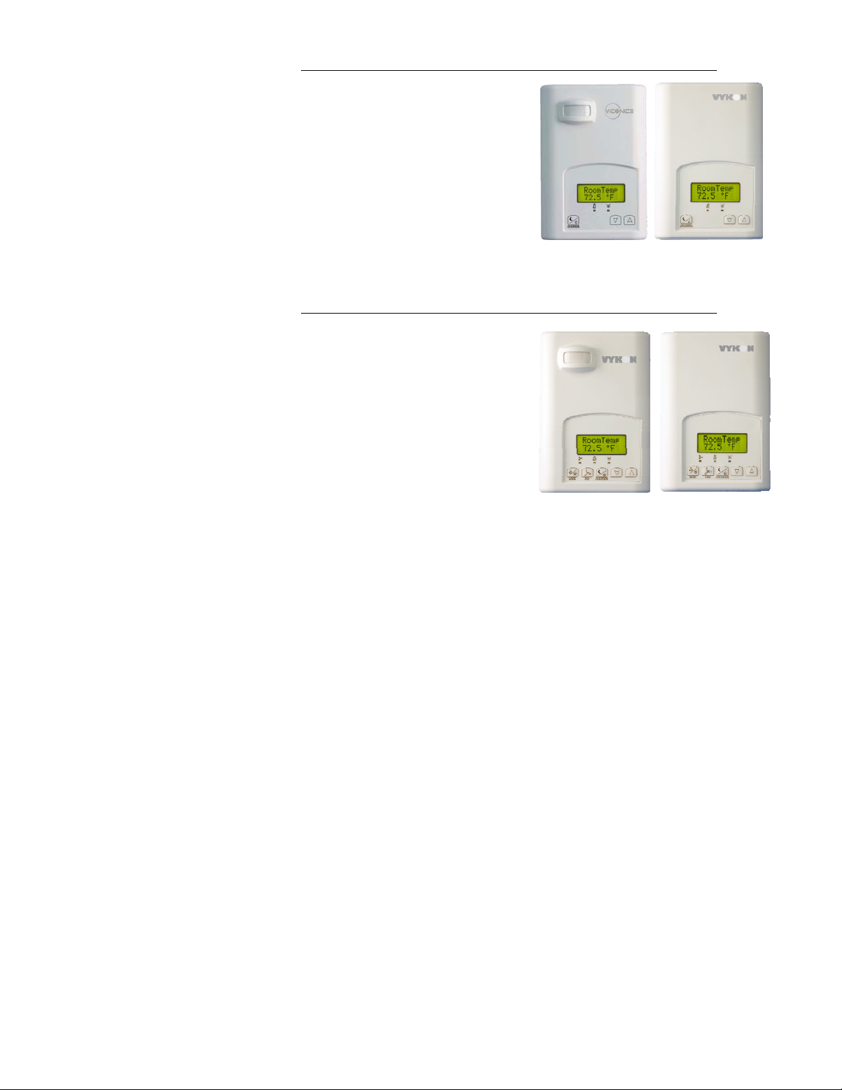
VT7200C5x28E
VT7200F5x28E
VT7300A5x28E
VT7300C5x28E
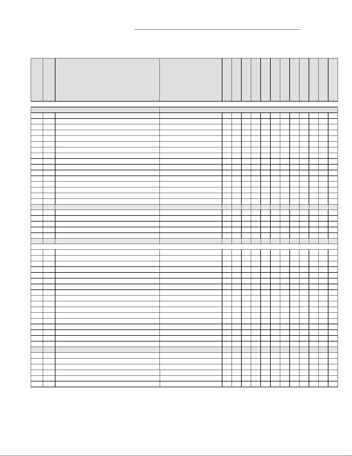
VT7350C5x28E
VT7305A5x28E
VT7305C5x28E
VT7355C5x28E
VT7300F5x28E
VT7350F5x28E
VT7305F5x28E
VT7355F5x28E
N/A: Not applicable on this model
0 nviSpaceTemp SNVT_temp_p X X X X X X X X X X X X
1 nviOutdoorTemp SNVT_temp_p X X X X X X X X X X X X
2 nviSetpoint SNVT_temp_p X X X X X X X X X X X X
3 nviSpaceRH SNVT_lev_percent N/A N/A N/A N/A X N/A N/A X N/A X N/A X
4 nviFanSpeedCmd SNVT_switch N/A N/A X X X X X X X X X X
5 nviAuxHeatEnable SNVT_switch X X X X X X X X X X X X
6 nviOccManCmd SNVT_occupancy X X X X X X X X X X X X
7 nviApplicMode SNVT_hvac_mode X X X X X X X X X X X X
8 nviHeatCool SNVT_hvac_mode X X X X X X X X X X X X
9 nviRemLockout UNVT_count X X X X X X X X X X X X
10 nviDhumiLCK SNVT_switch N/A N/A N/A N/A X N/A N/A X N/A X N/A X
11 nviAuxOut SNVT_switch X X X X X X X X X X X X
12 nvoSpaceTemp SNVT_temp_p X X X X X X X X X X X X
13 nvoDischAirTemp SNVT_temp_p X X X X X X X X X X X X
14 nvoSpaceRH SNVT_lev_percent N/A N/A N/A N/A X N/A N/A X N/A X N/A X
15 nvoEffectOccup SNVT_occupancy X X X X X X X X X X X X
16 nvoUnitStatus SNVT_hvac_status X X X X X X X X X X X X
1 mode x x x x x x x x x x x x
2 heat_output_primary x x x x x x x x x x x x
4 cool_output x x x x x x x x x x x x
6 fan_output N/A N/A x x x x x x x x x x
7 in_alarm x x x x x x x x x x x x
17 nvoSccStatus UNVT_thermo_state_fc X X X X X X X X X X X X
Associate with UNVT_thermo_state_fc format file
1 bi1_status True bit index 2 x x x x x x x x x x x x
2 bi2_status True bit index 1 x x x x x x x x x x x x
3 ui3_ status True bit index 0 x x x x x x x x x x x x
4 dehumidification_active True bit index 7 N/A N/A N/A N/A x N/A N/A x N/A x N/A x
5 state_terminal_bo1 True bit index 13 x N/A N/A x x N/A x x N/A N/A N/A N/A
6 state_terminal_bo2 True bit index 12 x N/A x x x x x x N/A N/A N/A N/A
7 state_terminal_bo3 True bit index 15 x N/A x x x x x x N/A N/A N/A N/A
8 state_terminal_bo4 True bit index 14 x N/A N/A x x N/A x x N/A N/A N/A N/A
9 state_terminal_bo5 True bit index 20 x x x x x x x x x x x x
10 fan_low True bit index 21 N/A N/A x x x x x x x x x x
11 fan_med True bit index 22 N/A N/A x x x x x x x x x x
12 fan_high True bit index 23 N/A N/A x x x x x x x x x x
13 window_opened True bit index 24 x x x x x x x x x x x x
14 service_alarm True bit index 28 x x x x x x x x x x x x
15 filter_alarm True bit index 29 x x x x x x x x x x x x
16 local_pir_motion True bit index 39 x x x x x x x x x x x x
18 nvoTerminalLoad SNVT_lev_percent X X X X X X X X X X X X
19 nciSetpoints SNVT_temp_setp X X X X X X X X X X X X
1 occupied_cool x x x x x x x x x x x x
2 standby_cool x x x x x x x x x x x x
3 unoccupied_cool x x x x x x x x x x x x
4 occupied_heat x x x x x x x x x x x x
5 standby_heat x x x x x x x x x x x x
6 unoccupied_heat x x x x x x x x x x x x