M1.2.CUT80HFI.NLFREN 09102018
8
NL
3 Installatie en aansluiting
3�1 Aansluitingsvoorwaarden
1) Aansluiting van de ingangskabel
Voor uw veiligheid, en om elektrische schokken te voorkomen, verbind de machine op betrouwbare wijze aan de aarde,
door de aardingsdraad (geel-groen) van de machine aan de aardingsaansluiting van de schakeldoos aan te sluiten.
Een primaire voedingskabel is beschikbaar voor deze snijmachine. Sluit de voedingskabel aan het nominale
ingangsvermogen aan. De primaire kabel moet aan de correcte stopcontact goed aangesloten worden, om oxidatie te
voorkomen.
Controleer met een multimeter, of de spanning in aanvaardbaar bereik varieert.
De doorsnede van de leidingen in de schakeldoos moet aan de vereisten van de maximale ingangsvermogen van de
machine voldoen.
2) Aansluiting van de uitgangskabel
Aansluiting van de snijtoorts
Verbind de koperen moer op de snijtoorts met de gas-elektriciteit aansluiting op het
voorpaneel van de machine, en draai met de klok mee om gaslekkages te voorkomen.
Steek de snelstekker op de werkstukklem in de “+” uitgang op het voorpaneel van de
machine, en draai deze vast.
Aansluiting van de toortstrekker
Steek de stekker van de trekker op de snijtoorts in de aansluiting van de toortstrekker
op het voorpaneel. Installeer de elektrode in de snijtoorts door deze langzaam te
draaien, en draai deze vast. Installeer vervolgens het mondstuk en de beschermhuls in
de juiste volgorde.
Aansluiting van de aardingskabel
Steek de snelstekker van de aardingskabel in de snelle aansluiting met het symbool
aan de onderkant van het voorpaneel van de machine, en draai deze vast. Klem het
werkstuk met de werkstukklem aan de andere kant van de aardingskabel.
3) Werking van het reduceerventiel
De ingebouwde lterdrukregelaar wordt in de fabriek ingesteld, en moet normaal niet door de gebruiker geregeld
worden. Als deze toch ingesteld moet worden, open de afdekkap van de machine zoals hiernaast afgebeeld, en ga als
volgt te werk:
1. Start de gasstroom.
2. Duw de drukregelknop omhoog.
3. Stel de gasdruk tot de gewenste waarde in, door de knop te draaien (draai naar “+” om de druk te verhogen, draai
naar “-” om de druk te verminderen).
4. Duw de drukregelknop omlaag, om deze te vergrendelen.
5. Voer het water af door de afvoerknop te draaien wanneer er te veel water in de lterbeker.
6
2. INSTALLATION AND CONNECTION
2.1 Installation requirements
In order to ensure personal safety and avoid electric shock, please ground the machine reliably
by connecting the ground wire (yellow-green wire) of the machine to the grounding device in
the switching box.
1)Connection of input cable
A primary power supply cable is available for this cutting machine. Connect the power supply
cable to the rated input power. The primary cable should be tightly connected to the correct
socket to avoid oxidization. Check whether the voltage value varies in acceptable range with a
multi-meter.
The cross section of the leads used in the switching box should meet the requirements of the
maximum input capacity of the machine.
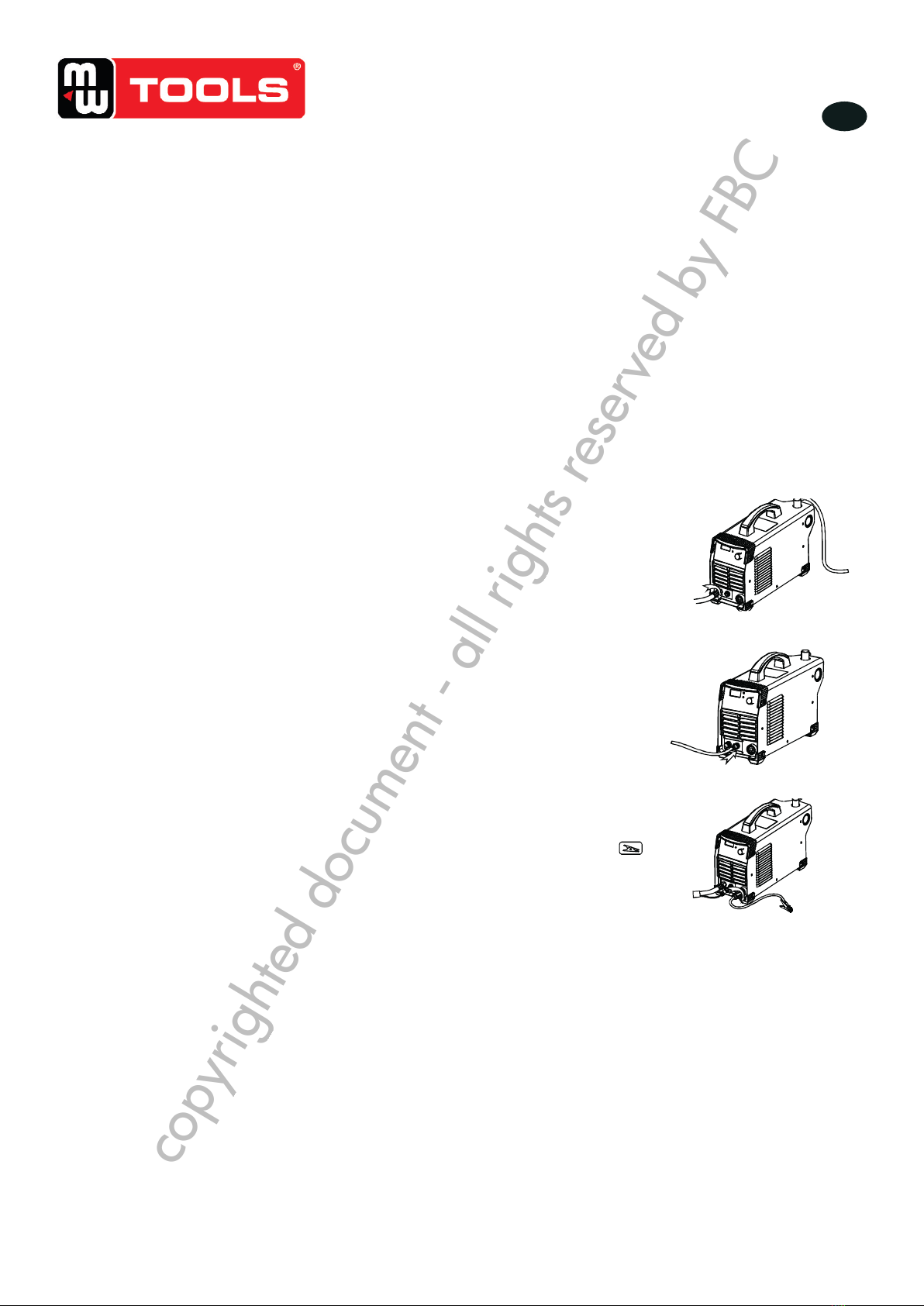
2)Connection of output cable
Connection of cutting torch
Connect the copper nut on the cutting torch to the
gas-electric connector on the front panel of the
machine, and tighten it clockwise to avoid gas
leakage. Insert the quick plug on the work clamp
into the “+” output terminal on the front panel of the
machine, and tighten it clockwise.
Connection of the torch trigger
Insert the plug of the torch trigger on the cutting torch
into the socket of torch trigger on the machine panel.
(For models with pilot arc function, connect the pilot
arc wire on the cutting torch to the terminal for pilot
arc wire on the machine panel.) Install the electrode
into the cutting torch by turning it slowly, and tighten
it. Then, get the nozzle and protective sleeve installed
in sequence.
Connection of earth cable
Insert the quick plug on the earth cable into the quick
socket marked with “ ” at the bottom of the front
panel of the machine, and tighten it clockwise. Clamp
the workpiece with the work clamp at the other end of
the earth cable.
6
2. INSTALLATION AND CONNECTION
2.1 Installation requirements
In order to ensure personal safety and avoid electric shock, please ground the machine reliably
by connecting the ground wire (yellow-green wire) of the machine to the grounding device in
the switching box.
1)Connection of input cable
A primary power supply cable is available for this cutting machine. Connect the power supply
cable to the rated input power. The primary cable should be tightly connected to the correct
socket to avoid oxidization. Check whether the voltage value varies in acceptable range with a
multi-meter.
The cross section of the leads used in the switching box should meet the requirements of the
maximum input capacity of the machine.
2)Connection of output cable
Connection of cutting torch
Connect the copper nut on the cutting torch to the
gas-electric connector on the front panel of the
machine, and tighten it clockwise to avoid gas
leakage. Insert the quick plug on the work clamp
into the “+” output terminal on the front panel of the
machine, and tighten it clockwise.
Connection of the torch trigger
Insert the plug of the torch trigger on the cutting torch
into the socket of torch trigger on the machine panel.
(For models with pilot arc function, connect the pilot
arc wire on the cutting torch to the terminal for pilot
arc wire on the machine panel.) Install the electrode
into the cutting torch by turning it slowly, and tighten
it. Then, get the nozzle and protective sleeve installed
in sequence.
Connection of earth cable
Insert the quick plug on the earth cable into the quick
socket marked with “ ” at the bottom of the front
panel of the machine, and tighten it clockwise. Clamp
the workpiece with the work clamp at the other end of
the earth cable.
copyrighted document - all rights reserved by FBC