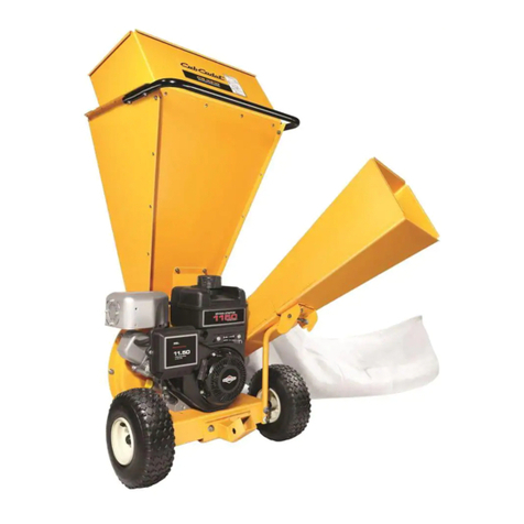
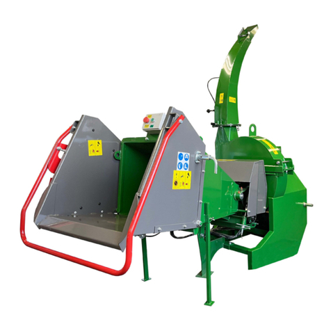
W-W Grinder renegade 250 User manual

IL
=
GRINDER
INC.

,
...
,
I
I
INTRODUCTION
w-w
GRINDER
INC.
Mail: P.O.
Box
4029, Wichita, Kansas 67204 •
Office
and Factory: 2957 N. Mark.et • Telephone (316) 838-4229 • 8CO-835-2127
Dear Customer,
It's a pleasure to have you as an owner
and
to introduce
you
to
the capabilities of the
Renegade 250.
We
believe you have selected one of the finest units available for personal use.
The new Renegade 250
is
designed for the person who wants
to
keep
their
garden and
yard
beautiful.
It
is
a tough built, yeteconomicai Chipper
/S
hredder/Grinder. With the Renegade
250 you can recycle valuable waste
materia
l
s.
We
have designed a number of features into the Renegade 250 which makes
it
easy to
handle, a pleasure
to
use and convenient
to
store. Our business specializes in designing and
manufacturing machines
that
break. shred and grind organic materials and
other
wastes. The
Renegade 250 model meets those objectives superbly and
is
built
to
a high sta
ndard
of
quality
to
last
you
a lifetime.
I think
you
will find the Renegade 250 model
is
a tough, efficient machine
that
will reduce
huge quantities of materials
to
sprea
da
ble mulch or compost in a sho
rt
time, adding
to
the
beauty and productivity of your property.
Again,
we
are very pleased
to
have
you
as an
ow
ner
of
on
e
of
our
products and
ar
e
co
nfident
that
it will serve y
ou
wen.
Sincerely,
~R"
~~
. .
Brij
~ani
V
ic
e
if.f~sident
& General Manager
W·W Grinder Inc.
MANU
FACTURERS OF SHREDDER/
GRINDERS
, POWER SPRAYERS.
MAGNETIC
SWEEPERS

WARRANTY
w-w
Grinder
Inc.
warrants
to
the
origina
l purchaser of this
product
that
the
same
is free of defects
in
materials
or
workmanship
for
a period of one (1) year from the date
of
purchase, except when
used
for
commercial purposes, and agrees to repair or replace at
no
cost
to purchaser
for
labor or materials. any
part
or parts which shall be determined to
be
defective
by
WoW
Grinder Inc. after examination.
Commercial use
warranty
is for a pe
ri
od of ninety (90) days from
date
of
purchase. In the event of a defect
or
malfunction
during
this warranty.
the purchaser
is
to return the
part
to
WoW
Grinder Inc., 2957 North Market, Wichita,
KS
67219.
All
transportation costs
on
parts submitted
for replacement under this warranty must
be
borne
by
the purchaser. This warranty presumes reasonable
care
of the product
by
the purchaser
and does not cover misuse, abuse, neglect or damage caused
by
transporting or accident.
Al!
motors, eng
in
es,
tires, bearings or other component
parts
furnished with this product, but not manufactured
by
WoW
Grinder In
c.,
are covered under this warranty except as
mod
if
ied
by
the respective manu
fa
cturers thereof,
whose
names and addresses as well as a copy
of
the warranty provisions
to
these components will
be
furnished
upon
request.
The warranty is made
in
addition to and not
in
limitation of the implied warranties of merchantability and fitness for a particular purpose
pursuant to the laws
of
the State
of
Kansas. Further, this warranty gives
you
specific legal rights and
you
may also have other rights which
va
ry fr
om
state to state.
2957
N.
Market
S1.
Wichita, Kansas 67219 Phone 1-800-835-2
127
WARNING TO
CALIFORNIA
OWNER/OPERATORS
Under California Law. you
are
not permitted
to
operate an internal combustion engine using hydrocar-
bon
fuels on any forest covered, brush covered or
grass
covered land; or
on
land covered with grain. hay. or
other flammable agricultural crop without an engine
spark
arrestor
muffler in continuous effective working
order. The engine
on
your Renegade 250 Chipper/
Shredder
/Gr
inder. like most garden equipment. is an
internal combustion engine
that
burns
gasoline (a
hydrocarbon fuel). The Renegade 250
is
not equipped
with a
spa
rk
arrestor
muffler; therefore. it
must
be
equipped bythe purchaser witha
spark
arrestormuffler
in proper working order. The
spark
arrestor
must
be
attached
to
the engine
exhaust
system in such a
manner
that
flames
or
heat
from the system will not ignite
flammable material.
Failure
of the operator to comply
with this regulation is a misdemeanor under California
Law.
TABLE OF CONTENTS
Page No.
Section
I:
ASSEMBLY & PREPARATION
1.
Inspecting
after
delivery
............
. .
.........
.
..
2
2.
Uncrating and assembly
.........
..
...................
2
3.
Servicing the engine
.................
.
.............
...2
Section II. SAFETY INSTRUCTIONS
1.
Precautions before
starting
...........................
3
2. Things
to
avoid
in
operating
........
.......
.........
.4
3. Operational safety
............................
.
......
.4
4. Safety minded maintenance and storage
..........
...4
5.
Decal safety ..
......
..
....
.
............
.
...............
5
Section III:
THE
CHIPPERISHREDDERIGRINDER-
HOW
IT
WORKS
1.
Features and controls
.................................
6
2.
Shredder/Grinder
....................................
7
3. Chipper
................................
.
........
.
.....
7
4.
Power transmission
..................
_
................
7 1
Page No.
Section IV: OPERATING INSTRUCTIONS
1.
Materials suitable for the chipper
................
.
..
.8
2. Materials suitable for the sh
redder/grinder
..........
8
3.
Site selection
..........
.
.......
.
.......
....
.
..
......
...8
4. How
to
use the chipper
......................
.
........
8
5.
How to use the
shredder
/
grinder
..
....
.
..
....
...
.
.. ..
9
Section
V:
MAINTENANCE & SERVICE
1.
Engine..
...... .... ..... .. . .
..........
11
2. Power transmission
..
,
...............................
11
A. Clutch
........
........
.
.........................
11
B.
V·Belt
..........................
..
......
..
.......
12
g
..
~~~:r~~::::::
:::::::::::::::
::::::::::::::
:i~
3.
Chipper/Shredder/Grinder
..........................
14
A.
Grinder
hammers
and shaft
.........
.
.........
14
B.
Chipper section
...
.
.......
.
.. ..
.................
15
C. Hopper
..............
.
...............
.....16
D.
Wheels and axle
...................
.
........
...
.16
Section VI:
TROVBLESHOOTING
...................
17
Section VII: PARTS
LIST
......................
..
.......
19

r I
I
""-
I
I
SECTION
I:
Assembly
and
Preparation
A WARNING:
Do
not operate this
equipment
until
.....
'you
ha
ve
read
and
understood your manual and
equipment.
CAUTION: Motor
oil
mu
st be added
to
the engine before
starting. (See Step 3
.)
STEP
1:
Inspecting
after
delivery
NOTE:
Inspect your
equipment
while
it
's still sec
ured
to
the shippi
ng
pallet to see
that
it
arrived
in
good
co
ndition.
If
you find or suspect any
damage
(either the eq
uipment
or the box), phone the trucking company (carrier)
or
d
ea
ler
from whom you purchased your equipment
right
away.
Info
rm
them of
the
damage and te
ll
them
you
wish to file
a claim.
Be
sure
to
put
this
in
uniting
to
the
carrier within
15
days, The
carrier
will let you know how
to
proceed with
a claim
to
ac
hi
eve satisfaction.
Of
course, let us know if
yo
u need assi
sta
nce with a shipping problem.
STEP
2:
Uncrating
and
assembly
Now
that
you have removed the box and
are
familiarizing
yo
urself with
the
manual, proceed as
fo
llow
s:
1. Remove the tie down holding the handle
to
the
pallet.
2. Remove the hold-down
brack
et
at
the fron
tsta
nd.
3. The
Parts
Kit (located in the chipper c
hut
e)
should
contain the following:
Item Description Qty.
Owner's Manual.
...
..
...
...
..
..
..
.........................
1
Engine
Manual..
.
....
..
...
.
....
..
....
..
,..
..
...
..........
1
Goggles
.................
....
..
..
•...
•..
.
•...•.
...
...•......
1
THMS
114-20
x1
114"
Whiz-Nuts 1/4-20.
............
.
........
.4
.
............
......
..
................
4
Allen Wrench 1/4" (For Knife)
...
.
........
..
.
......
1
Allen Wrench 5/32" (For Lock Collar)
........
...
..........
1
Lockwasher, 3/8" internal tooth, spare
for rod retainer pl
ate
...............
. ..
....
..
........
1
Knife Clearance Gauge
.....
.........
.
....
.....
....
.
.....
..1
2
4. Ins
ta
ll
the handle with the four
truss
head machine
screws
(11
/4-20 x
11
/4") and the four Whiz-Nuts using
a #2 Phillips screwdriver and a 7/
16
" wrench,
and
tighten securely. (See photo L)
(Photo 1)
STEP
3:
Servicing
the
engine
A
WARNING:
Engine
must
be off and s
park
plug
wire disconnected before any maintenance or
service procedures are performed.
Please refer to your engine operating and maintenance
instruction manual w
hi
ch was included
in
your literature
package.
Your
nearest
au
thorized service center
for
the
engine
on
yo
ur
Rene
gad
e 250 can handle all repairs,
par
ts
,
orders and warranty service
on
your engine. (Refer to
Section
VoL)

"-
•
SECTION
II:
Safety
Instructions
WARNING:
READ THIS MANUAL
Incorrect usage
of
this machine may result
in
severe
injury. Personnel operating and maintaining it should
be trained in the proper use, should be
warned
of
dangers
involved, and should read the
manuals
completely and thoroughly before attempting
to
set-
up, operate, adjust
or
service this machine.
SAFETY FIRST!
This is a safety
alert
symbol,
which will be used
to
call your
attention
to
a safety message to
warn you of' possible danger to
your personal safety. When you
see
this symbol it means
you
should
become alert, your personal safety
is involved.
Warnings,
cautions,
notes
In
this manual. Warnings call attention
to
practices
or
procedures which may cause personal injury
or
death. It
is
the
owner's
responsibility
to
see that machine operators
have access
to
adequate instructions about safe operating
a
nd
maintenance procedures. Cautions call attention
to
practices
or
procedures w
hi
ch
may cause damage to your
equipment. Notes give pertinent information that helps
make operation and maintenance more efficient.
Before operating this equipment read all appropriate
manuals, paying particular attention to safety precautions
in this manual and
engine
owner/operator's manuals.
11..
WARNING:
Always keep hands and feet out from
.....
under
machine
whenever
engine
is
running.
Always
turn
off and disconnect
spark
plug
wire
before makingadjustments
or
servicingequipment.
The
W-
W Grinder Renegade 250
is
as safe as good design
is capable of
making
it.
Safety
decals
The safety decals should be replaced if they
are
damaged,
co
vered over or otherwise become illegible. See IPL section
of this manual for appropriate
part
numbers.
Additional
safety
precautions
Keep hands, feet and clothing away from moving parts.
Keep hands and feet away from whirling hammer and
chipping blades.
Before servicing hammers or blades or performing
maintenance in chipping/shredding/grinding chamber:
• Engine
must
be off and
spark
plug wire disconnected.
(See photo 2.) 3
(Photo
2)
• Engine stop switch is designed to stop engine when
it
is
engaged with
spark
plug.
Do
not touch
spark
plug
when using stop switch
or
you may receive a shock.
(See illustration A.)
SPARK
PLUG
STOP SWITCH
(illustration
A)
1.
Precautions
before
starting
Read and
understand
your manual!
If
you do not
understand, list your questions and call your dealer or
W
-W
Grinder for an explanation.
We
want you to operate
your equipment safely and efficiently.
1.
Wear approved safety glasses or goggles and work
gloves.
2. Wear work clothes. Avoid
loo
se sleeves, shirttails, neck-
ties, oversize gloves, or other clothing or jewelry
that
might
get
caught in moving equipment.
A
WARNING:
Beforechecking hardware, disconnect
~
spark
plug wire from
spark
plug
to
prevent any
possibility of accidental engine
starting
.

SAFETY INSTRUCTIONS
3. Check all fasteners (screws, nuts, bolts, V-belt, wheels,
etc.) and
co
mponents for security.
4. Check
that
the
cylinder rotates freely by reaching
through the
rubber
fl
ap
with a stick and
sp
inning the
hammers
in
either
direction.
If
an obstruction is preSent,
clear
the
chamber
as instructed
under
Operational
safet
y,
item
number
22.
5.
Move
the unit
to
your work site. (Refer
to
Sect
i
on
IV-3.)
2. Thi
ngs
to
avoid
in
operatin
g
If
you let anyone else operate your machine
or
work with
you, be
sure
they
are
thoroughly instructed
to
the
safe
operation of the
mach
in
e.
6.
Do
not allow ch
il
dren
to
operate machine.
7.
Do
not allow bystanders
near
the machine when you
are
chipping
or
gr
inding materials.
8.
Do
n
ot
put
your face or body in frontof
the
feed openings
while operating.
9.
Do
not stand
in
front of the discharge
area
when
operat
ing.
10.
Do
not
operate
on
a paved or gravel surface.
11. After towing your machine over uneven
or
rough
terrain, make sure
you
have
no
gasoline spill before
starting engine.
12.
Do
not
run
the
engine in an enclosed area, carbon
monoxide fr
om
the engine exhaust is
an
ext
remely
poisonous gas, which
is
also colorless, odorless
and
tasteless.
13
.
Do
not operate with
dr
ive belt
guard
removed.
3.
Opera
ti
onal
safety
14. Make
sure
the
unit
is level and stable before
starting
or
operating.
15. Always
run
engine
at
full
RPM
while
gr
indi
ng
or
chipping.
16.
Do
not
put
handsor anyother par
tofthe
body orclothing
inside
the
feed hopper,
chipper
chute,
di
scharge
openings
or
near screen area
or
any moving parts.
17. Keep all safety
guards
(screens and deflectors) in place
an
d in
goo
d operat
in
g conditi
on.
18.
Do
not overreach when feeding material. Keep good
balance and footing
at
all times.
19. When feeding shreddable
materia
l in the chipper/
grinder
be
ext
remely careful
that
foreign objects (rocks,
metal, bottles)
are
not included.
20.
If
the cutting mechanism strikes a foreign object
or
if the machi
ne
starts making
an
unusual noise
or
vibration, immediately
shut
off the engine. Disconnect
the
spark
pl
ug
wire from
the
spark
pl
ug
and
take
the
following steps:
a. Inspect for damage.
h. Check for and tighten any loose parts.
c.
Replace or repair damaged parts.
21.
Do
not allow processed
mater
ial
to
build up
in
the
discharge area; this may prevent proper discharge
and
can result in kick-back of
materia
l through
the
feed
ope
ni
ng.
22.
If
the chipper/
grinder
becomes clogged,
shut
off the
engine
and
disconnect
the
spark
plug wire before
cleaning. Use a
wood
stick
to
clear debris.
23.
Do
not l
et
the
eng
ine and drive belt
get
clogged with
debris that could cause engine overheating
or
damage
to
the
belt.
24.
Do
not
try
to adj
ust
the
engine governor setting. The
governor controls the maximum safe operating speed,
4
protecting
the
engineand all moving
parts
from
damage
caused by overspeed.
25. For safe operation do not relocate
or
transport
this
machine while it is
runn
i
ng.
26.
Avoid
the possibility of fire
or
explosion; neVer refuel
....
'
a
hot
or
running engine, allow engine to
cool
before
~
refueling.
4.
Safety
minded
m
aintenance
and
st
ora
ge
27. Make
sure
the
spark
plug wire is disconnected f
rom
the
spark
plug, before servicing, inspecting
or
for of
f-
season storage.
28. Allow
the
eng
ine and chipper/
grinder
components to
cool
before maki
ng
any inspections or adjustments.
29. Storeyour machine level and
outof
the reachof ch
il
dren
and where gasoline vapors will not reach
an
open flame
or
spark. Be sure engine is
cool
before storing.
30. Protect the engine from moisture when not in use.
If
moisture protection is not possible, run
engine
frequently.
31
.
For
off-season storage,
drain
the
gas
tank
by
runni
ng
engine until
it
stops from lack of fuel.
(Photo 3)
(Photo 4)

5.
MAKE SURE
THE
SAFETY DECALS
ON
YOUR
EQUIPMENT ARE KEPT CLEAN SO YOU
CAN
FOLLOW
THE INSTRUCTIONS
ON
THEM. (SEE PHOTOS 3 & 4.)
#1.
Appears on chipper and shredder hopper inlets and
discharge
(3
recuired)
#2. Appears on shredder hopper
#3. Appears on belt cover
#4. Appears on shredder hopper
#5. Appears on engine cover
(Please contact
us
for replacementdecals ifthey become
wo
rn
or
unreadable.)
ROTATING CUTTER BLADES!
KEEP
HANDS
AND FEET OUT
OF
INLET
AND DISCHARGE
OPENINGS WHILE
MACHINE
IS
RUNNING
NO HANDS
BELOW
THIS LINE
#1
Part Number2045-121
OPERATING
INSTRUCTIONS
1 REAO SAFETY RULES
AND
OPERATING
INSTRUC-
TION
S BEFORE
STARTING
UNIT
.
2. KEEP
HANDS
. FACE.
CLOTHING
.
CHILDREN
AND
PETS AWAY
FROM
INTAKE
HOPPER.
DISCHARGE
AREA
AND
MOVING
PARTS
.
3. USE APPROVED SAFETY GLASSES
AND
GLOVES
.
AVOID
WEARING
LOOSE-FITTING
CLOTHING
.
4.
IF
UNIT
JAMS
.
TURN
POWER
OFF
.
DISCONNECT
SPARK
PLUG
WIRE
AND
MAKE
SURE
ALL
MOVING
PARTS HAVE
COME
TO
A
COMPLETE
STOP
. USE
ONLY
A
WOODEN
STICK
TO
CLEAR.
5.
KEEP
ALL
SHIELDS
IN
PLACE
.
6
DO
NOT
: •
USE
HANDS
TO
CLEAN
DISCHARGE
AREA
DO
NOT
: •
INSTALL
RODS. SCREEN,
ADJUST
OR
SERVICe WHILE OPERATING:
DO
NOT
: • OPERATE ON UNEVEN
GROUND.
OR
PAVED OR GRAVEL SURFACE.
DO
NOT
: . OPERATE
GAS
UNIT
IN
ENCLOSED
AREA. •
FAILUAE
TO
HEED MAY RESULT IN
SERIOUS PERSONAL INJURY
#2 Part Number 2045-102
»O
<j..'"241
&*
)
5
SAFETY
INSTRUCTIONS
-
OPERATOR-
TO
AVOID
CLUTCH
DAMAGE:
G)FEED
MATERIAL
AT
A
STEADY
RATE.
®
DO
NOT
OVERLOAD
OR CAUSE THE
ENGINE
TO
"BOG"
DOWN
CONTINU-
ALLY.
@ "
STOP"ENGINEAND
CLEAR GRINDER
WHEN
OVERLOADED.
#3 Part Number2045-124
#4 Part Number 2045-120
TO
"ST
OP"
·M
OV
E
SWITC
H
SPARK
PLUG
#5 Part Number2045-133

SECTION III:
The ChipperlShredder/Grinder-How It Works
AWARNING: Before putting your Renegade 250
to
work, please read this section completely so you'll
know
how
you
r equipment works
and
the location
and function of all features and controls.
1.
Features
and
controls
!
Photo 5
1.
Shredder
/
gr
inder hopper
2.
Front
stand
3.
Chipper chute
4.
Recoil
starter
5.
Rod
cover
Photo 6
6.
Shredder
/
grinder
rubber
flap
7.
Engine
8.
Belt
guard
9.
Shredder
/
grinder
tilt back leg
Photo 7
10.
Shredder
/
grinder
screen
11.
Shredder
/
grinderscreen
rods
Photo 8
12.
Shredder
/
grinder
rods and ro
ll
ers (optional)
6

Photo 9
13.
Shredder
/
gri
nder
screen stops
14.
Shredder
/
grinder
reversible
hammer
s
Photo 10
15.
Chipper knife
16.
Retaining bolts
17.
Anvil
18
. Chipper disc
2. Shredder/Grinder
Material is fed through the shredder/
grinder
hopper and
is shredded and ground when the cylinder
hammers
force
it against the
shredder/g
rind
er
baffles and screen. When
the material has been shredded fine enough, it is forced
out through the perforations in the discharge screen. (See
illustration
R)
The reversiblecar
bon
steel hammersare mounted in pairs
and spaced in 7 rows across the cutting chamber. The
ha
mmers
rotate
at
3600 RPM. The
standard
di
sc
harge
7
THE
CHIPPERlSHREDOERlGRINDER -
HOW
IT
WORKS
HAMMER
CYLlNDu'E:!R~-lJ
!n
_
'-::::~,
-'l1-
&
HAMMERS-
DISCHARGE SCREEN
RODS
(illustration
8)
screen has %" perforations and
is
held
in
position with two
steel rods and the rod cover.
3.
Chipper
The chipper disc is on a sh
aft
in common with the
shredder/grinder, rotating
at
3600 RPM, and contains the
chipper knife. The rotating knife is separated from the
stationary anvil
by
a gap of 1/
16
to 1/8 inch.
Limbs
are
fed through the chipper chute which directs
the limb between the knife and the anvil, shea
ring
chips
from the limb.
The chips discharge through the samescreen
perfo~ations
as the shredder/grinder.
4.
Power
transmission
(See
Photo 11)
A centrifugal clutch is mounted on the engine shaft and
is disengaged for easy s
tarting
. After the engine
sta
rts the
RPM automatically increases, and rotates the clutch.
At
approximately 1800 RPM the clutch
starts
engaging and
is
fully engaged
at
2500 RPM and above. The engine will
continue
to
increase until 3600 RPM, controlled by the
governor.
The V-belt transfers the power from the clutch
to
the
chipper/
shredder/grinder
shaft through the pulley.
(Photo 11)

I
I SECTION
IV:
Operating
Instructions
Now
th
at
yo
u
are
famili
ar
with the components
an
d h
ow
they work. use
that
knowledge and the
fo
ll
ow
in
g information
to lea
rn
how
to
operate
you
r chipper/shredder/grinder
efficiently and safely.
1.
Malerials
suitable
for
the
chipper
Limbs, branches, vines, lumber, s
in
gularly or in
multipl
es.
Usually larger than 1/2" w
hi
ch wi
ll
easily
go
t
hr
ough the
3"
chipper chute. (Remove nai
ls
and/
or
metal
parts from old lumber.)
2.
Malerials
suitable
for
the
shredder/grinder
Limbs, branches, twigs, leaves, manure, garbage, grass,
sta
lk
s.
brush. vines.
so
d
or
soil.
wood
chips. hay and straw.
lumber. paper and cardboard. compost. and other misc.
materials (genera
ll
y
li
mbs. lumber etc. are 1/2"
dia
meter
or sma
ll
er).
3.
Sile
selection
The Renegade 250 may be pushed
or
pulled by the handle.
"Stop" the engine before moving.
Loc
ate the un
it
on
level ground
(dirt
or grass preferred).
adjacent
to
the material
to
be processed. Stand to one side
of the hopper(s)
so
that no
part
of the body is in line with
the hopper(s) when feeding or reach
in
g
for
material.
Pre-operational
checklist
1.
Service engine
2.
Select level site (preferably
dirt
or
grass)
3.
Put
on
goggles and
wo
rk gloves
4.
Visua
ll
y check hopp
ers
to
be free of obstructi
on
5.
Start
your engin
e!
Engine
starting
(See
Engine
Manual
.)
4.
How
10
use
Ihe
chipper
Li
m
bs
or branches
wi
th large stubs
or
fo
rk
s will have
to
be trimmed. however. smaller limbs with multiple
(
Pftoto
12)
Stand
to
one
side.
hold
branch
tinnly
.
teed
in
smoothly
. 8
branches will be squeezed together and guided by the
co
ne
shape as they
are
pushed into the chipper chute. (See photo
1
2.)
Push them
in
as rapidly as the
ch
ipper will cut them
without slowing the engine down
to
a
po
int
where it labors
or
the clutch tends to slip (and/or disengag
e.
appr
ox.
2500
RPM). (Refer
to
Section
V·2
. Ma
in
tenance.) When the
material
is
reduced to the
le
ngth
01
the chipper chute (See
pho
to
13
).
pull it
out
and feed into the shredder
/g
rinder
hopp
er
. (See photo 14 and Secti
on
IV·5.)
(Photo
13)
Stand
to
one side, do
not
force
short
material into
ch
ipper
chute
by
hand
,
feed
into
shredder
hopper.
(Photo
14)
Stand
to
one side,
feed
material
into shredder hopper
crosswise
as
shown.

A WARNING: Never
put
your hands into the chipper
chute. Short branch stubs may be pushed through
the chipper
with
the next branch.
Helpful
hints
• Rotate
large
limbs as cutting occurs.
• Several smaller limbs may be held together.
• Keep the branch away from your body.
5.
How
to
use
the
shredder/grinder
Material may be
put
into the hopper from any of the four
sides.
AWARNING: The
grinder
has a tendency
to
pull
long material,
or
large bundles
of
stringy
materials,
outof
yo
ur
hands,
so
don't hold on tightly.
If
material
does not feed itself,
do
not use your hands to force
material down the hopper through the split
rubber
fe
nce. Use a stick
that
will grind up if it comes
in contact with the cutting area. (See photo 15.)
(
Photo
15) Use a
stick
to
push
material through the rubber fence,
If
H
js
not
feeding
by
itseH.
Feed
at
an
even
rate.
Loose material(leaves, grass,etc.) maybe dumped directly
into the hopper. Use a stick and push small amounts through
the
rubber
flap
at
a steady, even rate. (See photo 15.)
Do
not overfeed
so
that
the chamber is
too
full. This will slow
the engine down
to
a point where it labors roughly or the
cl
utch tends
to
slip (and/or disengage, approx. 2500 RPM).
(Refer to Section
V-2
-Maintenance.)
NOTE: Occasionally, when
grinding
wet
or
green
material, a buildup will occur
on
the discharge screen,
g
rinding
dry
material will usually clear the screen. The
practice of alternating green or wet material with dry
m
ater
ial will keep the unit clean and clear.
Thesize of the perforations in thedischarge screen largely
determinethe fineness of thefinished material. The
standard
sc
reen installed
in
the machine has
%"
holes. This screen 9
OPERATING INSTRUCTIONS
is generally best for
making
compost. Screens with smaller
holes
are
available, which work well for
grinding
grain
into
livestock feed or such things as fine ground potting soil.
Wet,
gummy
materials will clog the
%"
and finer screens.
A
larger
1
~"
optional screen will handle this type of
material, producing a coarser ground compost. The optional
grinding
screen
sizes
available have
W',
X",
%",
72"
and
l~fI
perforations.
6.
Installing
and
shredding
with
rods
and
rollers
A still coarser cut compost and the recommended way
to
handle wet and heavy materials is
to
use the rods and
rollers supplied as optional equipment for the machine.
To
install the rods
and
rollers, remove the rod retainer
plate. (See photo 16.) Pull the two screen rods out from the
mountingholes. (See photo 17.) Remove the dischargescreen
(Photo
16)
(Photo
17)

OPERATING INSTRUCTIONS
and
you
are ready to install the rods and rollers. Always
use rollers with the rods when screen
is
not installed. Slide
a roller
on
each of the five rods and insert
in
proper holes.
(See photo
18.)
Reinstall rod retainer plateand you are ready
to
operate.
(Photo 18)
If
the materials
are
still too wet and gummy, remove some
of the rods and rollers
start
ing
at
the back of the chambe
r.
Always thoroughly clean grinding chamber after grinding
wet materials.
7.
Installing
screen
To
reinstall the screen, remove all the rods and rollers,
insert screen up from underneath until it is
in
slot and
againstscreen stopswelded in frame. Forproperfitofscreen
make sure slot
and
screen stops are clear of debris. (See
photo
19
.) Insert two of the screen rods through holes. (See
photo 17.)
Do
not
put
rollers
on
rods when using screen
10
or use more
than
two rods as this will block screen
perforations. Replace rod retainer plate.
(Photo
19)
Make
sure
screen
slot
and
stops
are
free
of
debris.
Helpful
hints
•
Move
the unitperiodically
to
keep thedischarged material
from blockingthedischargescreen. Pushdown
on
thehandle
liftingthefrontstand
clear
of the discharged pile of material
and pull backwardsapprox.18" and letthe front
sta
nd down
level behind the di
sc
harged pile of material.
• A wide (48" to 60"), long piece of plastic laid down
prior
to
sta
rting
under the discharge
area
will keep lawns clean
and is an easy way
to
pick up the discharged material.
• A 55-gallon plastic
bag
may also be used. The
bag
must
be placed with the opening under the discharge and the
remainder of the
bag
stretched out through the frontstand.
Move
the material toward the bottom'of the
bag
as required.

SECTION
V:
Maintenance and Service
For Renegade 250 service:
Yo
u'll find this Owner's Manual helpful for service
and
maintenance procedures,
so
be
sure
to
look
here
first
...
all the help you need may be
right
in this Manual. Look
at
the
Table of Contents for
subject
areas
and
page
references.
If
you
do
not find
the
answers you need in this Manual,
pl
eas
e
contact
your
dealer
or us by
letter
or phone.
Re
member
we'll need
the
Model and Serial
Number
of your
u
nit
to
give you the most efficient service.
IMPORTANT -WRITE DOWN THE
MODEL
AND
SERIAL NUMBER OF YOUR
REN
EGADE
250
If
yo
u contact your dealer or us, we'll need
to
know
the
MOD
EL
and
SERIAL
NUMBER
of your
unit
to
provide
f
ast
and efficient service. For ready reference, please record
yo
ur
model, serial
number
and date delivered
on
the
lines
be
low.
Ren
egade
Model
__________
____
____________
__
Se
ria
l
Number
of my Model is
__
________________
_
Date of Delivery
______________
____
____________
_
S
EN
D SERVICE
LETTERS
TO:
WOW
Grinder Inc.
P.O.
Box 4029
Wichita, Kansas 67204
OR
TELEPHONE:
Use our Toll-Free
Number
Call 1
-8
00-835·2127
In Kansas Phone 1-316-838-4229
(PIIoto 20) Your Identification plate Is located to the right
01
the engine
on the grinder
cham""'.
11
When calling, ask for
our
Technical Service Department.
Our Service Representatives
are
available from 8:00 A.M.
to
5:00 P.M. (Central time) Monday through
Friday
and 9:
00
A.M.
to
12:00 Noon
on
Saturday. ,
To
order
Renegade 250
parts from the factory:
For
parts
please write
or
telephone, using
the
address
or telephone
number
given. Before
writing
or
calling,
refer
to
the
parts
listing in
the
back of this Manual for
the
part
description and
part
number
of
each itemyou'll be ordering.
Be
sure
to
include this i
nforma
tion in your letter,
or
have
it
on
hand if you're calling us.
For engine service
and repairs:
Please contactyour
nearest
authorized Briggs &
Stratton
Service Center
if
engine service or
repair
is needed.\This
listing is in the phone book "Yellow Pages"
under
"Engines,
Gasoline" or "Gasoline Engines." The Service Center will
need to know the Model, Type and Code N
umber
of your
engine -Section V in
th
is Manual shows you how to locate
these numbers.
Your local Briggs&
Stratton
dealer can handleall repairs,
parts
orders
and
war
ranty
service concerning
the
engine
alone.
If
you wish
to
contactus beforeseeing
the
local
Engine
Dealer,
or
if you have difficulty
gett
ing engine service or
parts
locally, be
sure
to
let
us know. See the enclosed
Engine
Manufacturer's
literature
for full
terms
of
the
Limited
Warranty
on the engine
and
other details about the engine.
1.
Engine
The
engine
manufacturer
has supplied you with
an
Operating
and
Maintenance Instructions manual.
This
manual includes safety, service and
repair
information,
general information, before
starting
, starting, maintenance
and adjustments.
It..
WARNING:
Engine
must
be off
and
spark
plug
"wir
e disconnected before
any
maintenance
or
service procedures
are
performed.
2.
Power transmission
A. Centrifugal Clutch
Lubrication
-
After
15
hours of operation
or
every
12
months, apply several
drops
of
SAE
30 oil in the
area
of
the
retaining
ring
directly
after
use. (The oilite
bearing
will
tend
to
absorb
oil while
warm
from use.) (See
photo 21.)
Maintenance
-Allowingyour clutchto slip
and
overheat
(Refer to Section IV-
4,
5) will cause the oilite
bearing
to

MAINTENANCE & SERVICE
dry out prematurely
and
either
"wear"
itself out
or
"lock-
up". In
ei
ther
case the
cl
utch must be removed and
either
rebuilt
or
replaced.
You
can easily remove and replace the
clutch asfollow
s,
however rebuildingshould be done by your
dealer or a new one purchased from your dealer
or
the
facto
ry.
To
remove
and
reinstall
clutch
(Refer
to
"B. V-belt",
adjusting tension) -
To
remove clutch from shaft, loosen
s
et
screw
in
clutch hub first. (See photo 21.) Remove bolt
(Photo 21) (Clutch shown with belt guard removed -do not operate
without belt guard in place
.)
in end of shaft and concave washer which retains
shaft
key.
C
ar
efully remove clutch assembly from shaft, avoid using
hammers
or
pinch bars
th
at
could disto
rt
clutch
drum.
Save
key from engine
shaft
keyway.
After cleaning and examining, if clutch
is
damaged or
y
ou
suspect
it
is
damaged, take clutch
to
your Renegade
250 dealer for service
or
replacement parts.
To
reinstall clutch assembly
to
engine shaft, press key
into keyway and slide clutch onto shaft. Make sure
that
the
pulley
is
to the outside and align clutch pull
ey
with
grinder
pulley before tightening set screw. Replace washer
and
bolt
on
end of shaft making
sure
concave s
urf
a
ce
of washer
is
against end of shaft, tighten nut. " " .
B.
V-belt
A
WARNING:
Remove sp
ark
plug
wire
befo
re
checking or adjusting belt tension.
Check the belttens
ion
after the firstfew hours ofoperation
and adj"ust if necessary.
Remove the two bolts holding the
belt
guard
in place.
(Note the two flat washers used as spacers under the
low
er
bolt location.) When replacing make sure these washers
are
12
used
so
belt
guard
will mount flush with chamber.
Check the belt deflection as illustrated, )f" to
0/.
" being
desirable. (See photo
22
.)
(Photo 22) (Pulley shown with belt guard removed -do not operate
without belt guard in place.)
If
necessary to
adjust
the tension, loosen the four engine
mounting
bol
ts
so
the engine will slide. (See photo 23.) Make
(Photo 23)
adjustments by the two locknuts in the threaded shaft
under
t
the engine and retighten these nuts (See photo
24),
and
th
e
four engine bolts. Replace the belt guard. (See photo 25.)
If
replacement of the belt becomes necessary, the same
procedure is used.

(Photo 24) Loosen the 4 engine bolts (A) allowing the engine to move.
Adjust
the
belt
tension
with lock
nuts
on
threaded
shatto
(Photo 25) (Pulley shown with belt guard removed -
do
not operate
without belt guard
in
place.)
C. Pulley
The pulley is retained by two setscrews and anti·vibration
compound. Periodic inspection of alignment with the clutch
and security of
attachment
is recommended. Keep clean.
U
pon
replacing use Permatex
#2
on
set screws.
D. Bearings
The two
bearings
mounting
the
Chipper/Shredder
/
G
rinder
are
permanently lubricated and sealed,
requiring
no
maintenance. Should bearing replacement become
necessary (from Periodic Maintenance
chart
or
Trouble-
shooting chart) proceed as follows: 13
MAINTENANCE & SERVICE
1.
To
replace the
bearing
on the "pulley" side:
The inside nut is self retaining, therefore
no
wrench
is
required on the
nut
side. Remove belt guard. (See
"B. V-belt" this section.)
Slide the engine forward
to
put
slack in belt. (See
"A. Centrifugal Clutch" and
"B,
V-belt", this section.)
N
ow
the V-belt can be removed.
Remove the pulley by loosening the two set screws
(allen wrench) in the hub and sliding off the shaft. (See
photo 26.)
(Photo 26) (Pulley shown with belt guard removed -do not operate
without belt guard
in
place.)
(Photo 27) (Pulley shown with belt guard removed -
do
not operate
without belt guard
in
place.)

MAINTENANCE & SERVICE
The
bearing
lock collar is removed by
first
loosening
the
set screw (5/32" allen wrench). With
dr
ift pin in
collar hole
and
small
hammer,
tap the
lock collar in
the direction
opposite
to
shaft
rotation (clockwise this
pulley end) until
loo
se. (See photo 27.)
Remove the two nuts
(%/1
wrench)
retaining
the
bearing
and
slide
the
complete unit off the shaft. (See
photo 28.) Clean the
shaft
and
bearing
mounting area,
oil
lightly
and
install the new
bearing
(without the lock
collar),
tightening
the two nuts securel
y.
(Photo 28) (Pulley shown with belt guard removed -do not operate
without belt guard in place.)
Slide
the
new lock collar over the shaft, press lightly
against
the
bearing
inner ring, and
turn
collar in
direction
of
shaft
rotation
until engaged. With
drift
pin in ·collar hole, strike in
direction
of
shaft
rotation
to lock. Tighten set screw in
co
ll
ar.
Reinstall pulley, V-belt, adjust tension, secure engine
fasteners, and install belt guard.
2.
To
replace the
bearing
on the "chipper" side:
Follow the
same
procedure above
starting
with the
removal of the
bearing
lock collar.
3. Chipper/Shredder/Grinder
A
WARNING:
Engine
must
be off
and
spark
plug
wire
disconnected before any
maintenance
or
service procedures
are
performed.
A.
Grinder Hammers
and
Shall
1. Screen removal and clearing blockage:
With your Renegade250 on
firm
-level
ground
it
may
be
tipped back for easy access to
the
screen. (See photo
29.) (On soft
ground
a board may be used
under
the
tip back leg.)
14
Remove the wing nut, lock washer,
and
rod
retaining
cover
on
the
right
hand
(chipper) side.
Remove
the
two screen rods, and if the screen is
jammed
in tight, use
on
e rod as a handle
to
help in
removing screen. (See photo 30.)
(Photo 29)
(Photo 30)
Clear
the
grinding
chamber
area
by pulling
material
out. Rotate the cylinder
by
hand to
insure
all
material
is
out
. Clear the "screen stop"
areas
with a screwdriver
or small firm stick. (See photo 31.)
Replace the screen, rods and cover.
"

(PItoto 31)
CAUTION: Lock
tight
has
been
applied
by
the
manufacturer
at
the factory to the 1%" hex nuts
at
each
end of the cylinder shaft.
The
manufacturer
does not recommend field disassembly
of the
cy
lin
der
assembly. However,
if
field disassembly is
done,
heat
must
be applied to the nuts on the
cy
linder
shaft
to loosen them. When reassembling the cylinder shaft, a
medium strength lock
tight
must
be applied to the
shaft
thread and nut. The cylinder should also be rebalanced.
2.
Rep
lacing worn hammers:
Remove the screen. (Refer to Secti
on
II-3, 1.)
Block
hammers
from
turning
with
wood.
(See photo
32.)
(PItoto
32J
Each carbon steel
hammer
is attached to theassembly
with one bolt. Each
hammer
has two usable
cutt
i
ng
edges. The h
ammer
can be
turned
over
to
uti
li
ze the
second
cutt
ing edge by removing the bolt,
nut
and
two
lock washers (and possibly flat washers used
to
balance
the cylinder assembly). Make s
ure
these washers
are
replaced
in
the same position from which they
are
removed. Note
the
sequence
of
re
moval ofthese
parts
and replace in the proper order. Make sure bolts on
each end of
the
hammer
assembly
are
replaced with 15
MA
I
NTENANCE
& SERVICE
threads
to inside. (See illustration
C.)
If
both hammer
cutting edges
ar
e worn, replace the h
ammer
.
Reinstall the
sc
reen and rods in rever
se
or
der
of
removal.
USABLE
CUTTING
EDGE
WORN
EDGE
HAMMER
BO
LT
©f
n
FlAT
WASHER,
WHEN
USED
FOR
BALANCING
CYLINDER
BOLT NUT
LOCK
WASHER
WELD
(illustration
C)
Remove bolt to replace or rotate hammer.
B. Chipper section
1. Sharpen or replace knife:
Remove screen. (Refer to Section
V-3
,
1.
)
Block the h
ammers
from
turni
ng with
wood
and
remove
(2)
soc
k
et
head cap screws using the
W'
a
ll
en
wrench. (See photo
32
.)
Resharpen
to
a
30'
angle. (See illustration
D.)
Use
I
(illustration OJ
~
r-
SIDE P
LATE~
VCHIPPER
DISC
VCHIPPER KNIFE
v'
~
~
HEAD
-
-
~
CAP SCREW
1
/16
to 1
18
"-
(USE GAUGE)
(illustra
tio
n EJ

MAINTENANCE & SERVICE
a fine g
rit
bench grinder
at
home, or ha
ve
a machine
shop do the s
har
penin
g.
Clean the knife se
at
and adjacent
area
in
the chipper
disc before rein
sta
lling the knife. Reinstall the knife,
secure the two bolts with
lo
ckwashers and check the
knife cl
ea
rance.
2.
To
check and
ad
just
knife clearan
ce
(re
quir
ed only upon
replacement
of
both bearings and/or shaf
t):
Check clearance with gauge. (See illustration
E.)
Remove both bearing l
ock
collars (Refer
to
Section
V-2)
to
a
ll
ow
the
co
mplete
gr
ind
er
shaft assembly
to
move.
(Photo 33)
16
Use a plastic mallet or
hammer
and block of wood
to
move the shaft and estab
li
sh the proper clearance.
(See photo 33.)
Replace t
he
bearing lock
co
llar
s and other compo-
nents. (Refer
to
Section
V-2.)
C.
Hopper
Replacement
of
the
rubber
flap might become necessary
if fingers get torn
loose.
Replace with a new
part
by removal
and replacement of the four screws and washers. (See
Illustrated
Parts
Li
st.)
D.
Wheels
and
axle
An
all purposesp
ra
y-type lubricantshould be used
to
keep
wheels
in
good
operating condition. (See photo 34.)
(Photo 34)

TROUBLESHOOTING GUIDE
SYMPTOM
Hammer and chipper
unit
does
not rotate
Grinderunit is
not
cutting efficiently
Chipper unit is
no
t
cutting efficiently
Heavy vibration
or
unusual
noise
in
unit
PROBABLE
CAUSE
Solid
ob
ject
wedged in grinder
or
chipper
chamber
Dri
ve
belt is
no
t functioning
Clutch is
not
engaging
Engine
mounting
bolts and threaded
adjustment rod are loose and
engine has moved
Hammer/
chipper
shaft bearing
is locked in position
Grinder pulley is loose
Loose or damaged belt
Clutch slipping
Dull
or
damaged hammer blades
Damaged hammer
/chi
pper
shaft bearings
Engine n
ot
producing
high RPM
Dull
or
damaged
knife blade
Knife clearance incorrect
Loose
or
damaged belt
Cl
utch
slipping
Slot in
chipper
disc clogged
Damaged shaft bearings
Engine not producing
high RPM
Solid object in grinder
or chipper
chamber
Hammer blade(s) damaged
or
lost and
unit
is
out
of
balance
Chipper fl
yw
heel damaged
Chipper knife making
contact
with
an
vil
Hammer
/chi
pper
bearing(s) damaged
Engine
mount
ing bolts loose
Unit has loose
or
missing bolts
/n
uts
17
SUGGESTED
REMEDIES
Check
both
areas
for
any
obstruction
Check belt tension
Crutch Shoes are
worn
or
damaged.
Make
su
re engine
is
running
at full throttle
Check bolts for tightness
and
that
engine is properly
positioned with threaded
adjustment rod
for
correct belt tension
Check hammer/chipper shaft for
fr
ee
and smo
oth
rotation,
repl
ace
bearings, if
locked.
Check key in keyway and
tighten set screws
Tight
en
belt
or
replace
damaged belt
Check cl
utch
shoes
for damage
or
wear.
Make s
ur
e engine is running
at full
thrott
le
Check blades
for
damage
or d
ulln
ess, replace
or
turn
over to use second cutting edge
Check hammer/chipper shaft
for
smooth
rotation.
If
binding, replace bearings.
See
engine manual
for adjustments
Check blade for damage
and sharpness, replace
or
sharpen
Adjust
(
Reier
to
Section
V-3. 2.)
Tighten belt
or
replace
da
m
aged
be
lt
Check grinding chamber
for
obs
truction.
Clean slot o
ut
Check shaft
for
smooth rotation. If binding,
replace bearings.
See engine secti
on
of
manual for adjustments
Check
for
any obstruction
Check hammer blades
for damage and security
Check flywheel
fo
r
damage and security
of knife blade
Check anv
il/
knife
blade clearance
Check hammer/chipper shaft
for
smooth rotation,
replace bearings if binding
Check bolts
for
security
Check all fasteners in
grinder
/c
hipper for sec
urity
Table of contents