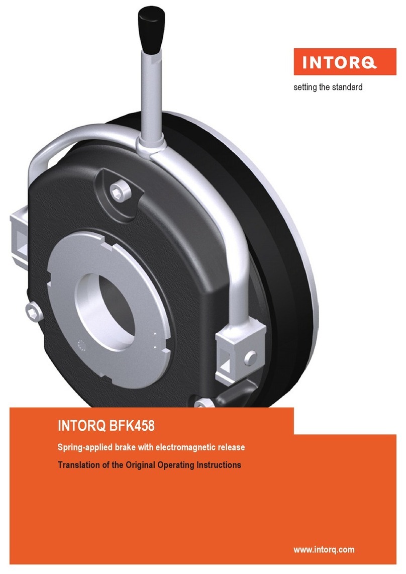
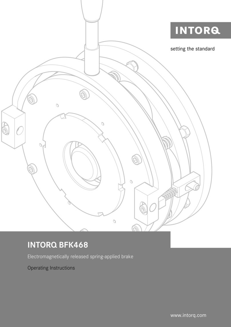
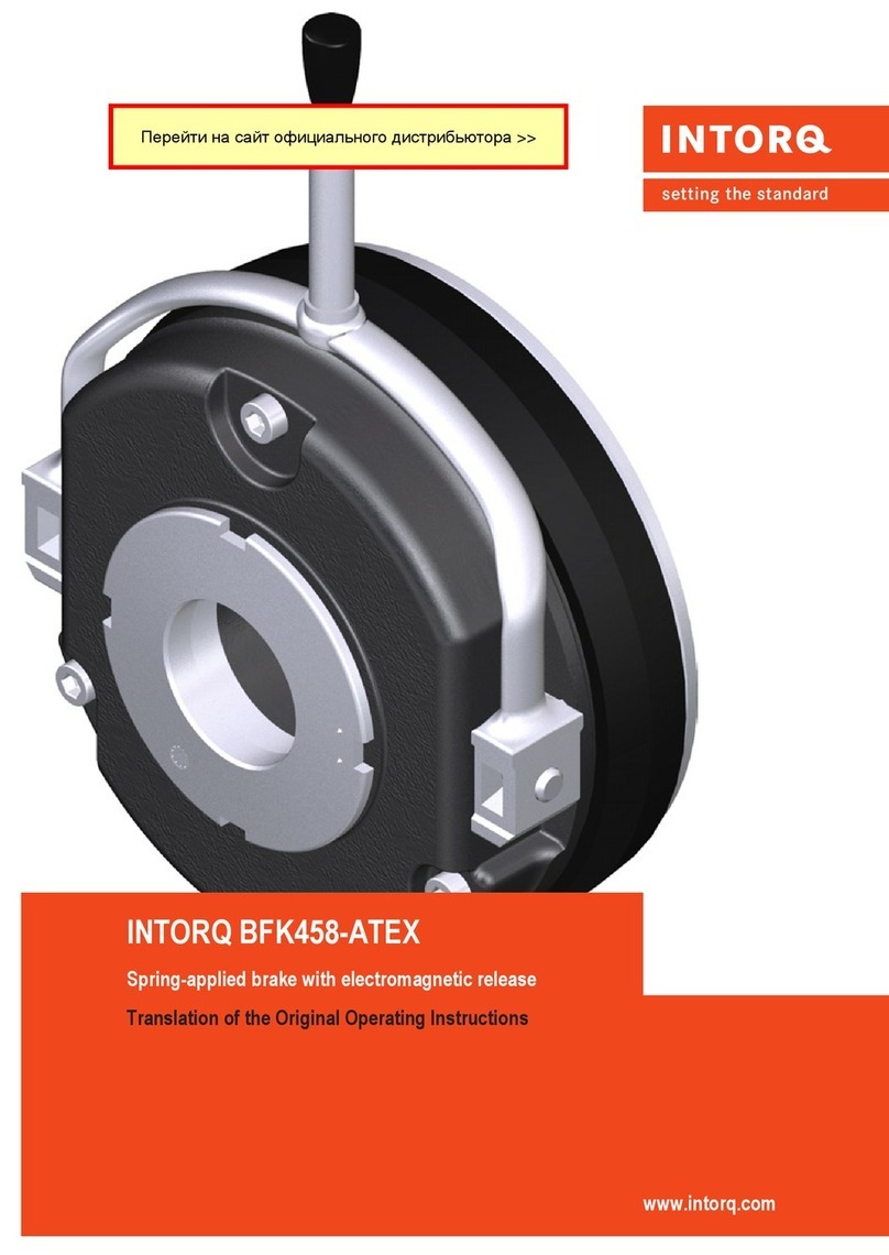
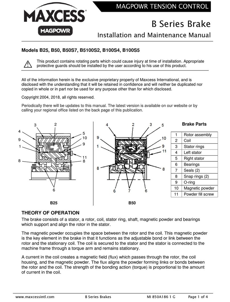
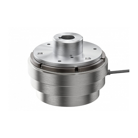
WABCO PAN 17 Quick guide

LEYLAND / DAF - Edition 12/2000
WABCO Mannheim
Mechanical Sliding Caliper Disc Brake
Type PAN 17
Assembly and Maintenance Instructions
WABCO Radbremsen GmbH
Postfach 71 02 63 – D-68222 Mannheim
Bärlochweg 25 – D-68229 Mannheim
+49 (0)6 21/48 31-0 FAX +49 (0)6 21/48 31-300

Disc Brake PAN 17
List of Contents Page
1. Description of the Mechanical Sliding Caliper Disc Brake 1
2. Service Instructions 3
2.1 Safety Tips during Repair 3
2.2 Checking Brake Function 4
2.2.1 Checking the Air Gap 4
2.2.2 Checking Adjuster Function 4
2.3 Checking Brake Pads 6
2.4 Checking Brake Discs 6
3. Renewing Brake Pads 8
4. Renewing Brake 14
5. Renewing Gaiters 15
5.1 Renewing Guide Pin Gaiters and Bushes 16
5.2 Renewing Adjuster Screw Gaiter 20
6. Checking / Renewing Brake Discs 22
7. Renewing Brake Cylinder 23
Table 1: Spanner Widths [AF]and Tightening Torques [Nm]26
Explosive Diagram of the PAN 17 Replacement Parts 27
LEYLAND / DAF - Edition 12/2000

Disc Brake PAN 17
LEYLAND / DAF - Edition 12/2000
1
1. Description of the Mechanical Sliding Caliper Disc Brake
The „PAN“ Brake is a Floating Caliper Disc Brake, designed for installation on front and rear
axles in trucks or buses as a Service, Emergency and Parking Brake. The brake is actuated
mechanically via a Diaphragm or Spring Loaded Cylinder which is mounted directly to a cover on
the brake caliper, resulting in a relatively short overall axial length and compact brake package.
The complete disc brake including brake cylinder consists of two assemblies, the brake caliper (1)
and the brake carrier (2).
Fig. 1
The brake caliper (1) slides axially on guide pins (8, 9) mounted in the brake carrier (2) and the
axially moveable brake pads (35, 36) are held in the brake carrier by a hold down hoop (38) and
hold down springs (37). Thereby the brake force is then transmitted to the abutment faces in the
brake carrier – shown in Fig. 1, 2 & 3.
The radially open design of the brake caliper allows for simple and quick changes of the brake
pads.
The actuation unit of the brake is equipped with an Automatic Adjuster to compensate for wear of
the brake pads and brake disc. This Automatic Adjuster, independent of load and operating
conditions, maintains a constant predetermined gap between brake pads and brake disc. This,
together with the robust and stiff construction of the brake caliper, ensures safe control of the
brake system and increases safety margins during emergency stopping.
The internal moving components of the brake are lubricated for life, and all sealing components
are maintenance free unless damaged.
1
2

Disc Brake PAN 17
LEYLAND / DAF - Edition 12/2000
2
Fig. 2 Plan View and Section
Fig. 3 Side View and Section
39 3835 3637 1
9
21
12
1
2
9
87
6
21
19
22
4
5
10

Disc Brake PAN 17
LEYLAND / DAF - Edition 12/2000
3
2. Service Instructions
The instructions with the following pictures encompass the necessary steps and work sequences
to replace the available repair kits. The spanner size and the tightening torques in the sequences
are listed in Table 1.
2.1 Safety Tips to be considered during Repair
The flawless technical condition of the Disc Brake is of utmost importance to ensure good driving
and safe braking characteristics.
Observe the wear limits of the brake pads and brake disc. When brake pads or brake disc are
damaged, or worn beyond their specified minimum thickness, brake effectiveness will diminish
and possibly result in an accident. Burned, glazed or oil contaminated brake pads must be
replaced immediately. Always replace brake pads on a per axle basis!
During repairs on the brake the vehicle must be parked on a level surface and be blocked to
prevent rollaway. Only approved and suitable fixtures are to be used for the lifting and blocking of
the vehicle. Danger of accident! While working on the brake it must be ensured that the brake
can not be actuated inadvertently. Do not actuate the brake when brake pads are removed.
Danger of Bodily Injury!
Do not clean the brake with pressurised air or other high pressure cleaning apparatus. Danger of
Bodily Injury!
Keep hands and fingers out of the inside of the caliper to avoid injury!
A second technician should assist during removal and installation of the brake. Heavy Load -
Danger of Bodily Injury!
During repairs outside of the vehicle, the brake must be secured in a fixture, such as a heavy
vise, as high torque is required during removal and installation of the bolts. Danger of Bodily
Injury!
The Brake Caliper with Clamping Unit shall not be opened, therefore the bolts holding the cover
shall not be loosened. No serviceable parts are inside the clamping unit.
Only original and genuine WABCO Service Parts and approved brake pads are to be used. With
newly installed brake pads avoid emergency stops and long braking cycles during the first 50 km
to prevent excessive temperatures.
For lubrication use only the tube of grease supplied with the brake repair kit.
During repairs use only recommended tools. Do not use a power-driven socket or tools! Tighten
Nuts and Bolts only to specified torque limits.
When wear of the cast brake parts, such as cracks or heavy abrasion, is observed, replace the
entire brake assembly according to instructions.
Upon completion of repairs the vehicles braking system must be tested on a roller dynamometer.
If no roller dynamometer is available a driving test with brake applications must be performed.
Disc Brake PAN 17
LEYLAND / DAF – Edition 12/2000
4
2.2 Checking Brake Function
Caution: Do not use a power-driven socket! Keep hands and fingers out of the inside of the
caliper to avoid injury!
2.2.1 Checking Air Gap:
Work Sequences Figures
•Loosen and remove hex head bolt 39 from
hold down hoop 38.
•Pull hold down hoop 38 out of brake caliper
1.
•Lift off the three hold down springs 37.
•Move cable guide 40 to the side.
Notice: Brake Pads and Thrust Plate stay in
place.
•Push the brake caliper towards the wheel
and check gap with feeler gauge.
0.5 mm ≤Air gap ≤1.2 mm.
Notice: Always insert feeler gauge between
brake caliper 1 and brake pad backing plate 35.
If the measured air gap is above specified
limits, the adjuster must be checked.
Fig. 4
Fig. 5
2.2.2 Checking the Automatic Adjuster
Work Sequences Figures
•Remove rubber plug 12.
•With closed end wrench set adjuster on the
hex nut 22 to 2 or 3 mm air gap.
Caution: Testing of the adjuster is possible
only with an air gap of between 2 mm and 3
mm.
Fig. 6
39
38
13740
12
22
1
35

Disc Brake PAN 17
LEYLAND / DAF – Edition 12/2000
5
Work Sequences Figures
The free space between closed end wrench
and caliper housing must be large enough so
that there will be no interference when the
adjuster rotates!
Important: Do not use power tools or an
open end wrench on the hex nut 22 of the
adjuster. Do not forcibly rotate the adjuster!
•Actuate the brake li
g
htl
y
5 times
(
approximatel
y
1 bar
)
. When the ad
j
uster
functions properl
y
the closed end wrench will
retract in steps in an anticlockwise direction.
Notice: The rotation an
g
le of the closed end
wrench will decrease with increasin
g
adjustments.
If the closed end wrench
a) does not rotate at all
b
)
onl
y
rotates durin
g
the first application of
the brake
c) rotates, and then retracts to neutral
then the adjuster is defective.
Replace Brake as described under Section 4.
•After checkin
g
the ad
j
uster, set the air
g
ap to
1 mm, as described in Section 3.
•Reinstall rubber plu
g
12 and ensure proper
seating of same.
Fig. 7
12, 22

Disc Brake PAN 17
LEYLAND / DAF – Edition 12/2000
6
2.3 Checking the Brake Pads
Notice: The brake pad thickness is to be checked regularly dependent on operating conditions
during maintenance intervals and under applicable local laws and regulations. Burned, glazed or
oil contaminated brake pads must be replaced immediately.
Always replace brake pads on a per axle basis!
Work Sequences Figures
Caution: To avoid damage to the brake disc
the brake pads must be replaced as soon as
one of the pads has reached its wear limit at
any one point.
A= Residual friction material thickness with pad
backplate should not be less than 9 mm.
Renew brake pads according to Section 3.
B= Total friction material thickness new without
pad backplate 19 mm.
C= Total normal pad thickness new 26 mm.
•After checkin
g
the brake pads, reposition
the cable
g
uide 40, insert the hold down
sprin
g
s 37 and secure the hold down strap
38 with hex head bolt 39 to the brake caliper
under specified tor
q
ue.
(
Table 1, Position II
)
.Fig. 8
2.4 Checking the Brake Discs
Work Sequences Figures
•Remove brake pads according to Section 3.
•Measure thickness of disc over the rubbin
g
faces.
D= Total disc thickness – new 34 mm.
E= Wear allowance limit 28 mm, the brake disc
must be renewed.
Caution: Observe brake pad and disc wear
limits. Worn-out pads and discs reduce the
brake effectiveness and can cause brake
failure!
Accident danger!
Replacement of brake discs must always be
performed on a per axle basis, never replace
only one disc of an axle! It is generally
recommended that, upon installation of a
new brake disc or after the disc has been
machine turned, new brake pads be
installed.
Fig. 9
Pad Backplate Friction
Material

Disc Brake PAN 17
LEYLAND / DAF – Edition 12/2000
7
Work Sequences Figures
Brake Disc Condition Inspection:
Check brake disc for cracks, condition of
rubbin
g
surfaces and maximum wear
dimension.
A = Crazing = permissible
B = Radial cracks max. 0.5 mm
(width) = permissible
C = Unevenness under 1.5 mm = permissible
D= Cracks across rubbing
surface = not permissible
a= Rubbing surface
Caution: When the brake disc is equipped
with an integrated (Fig. 11) respectively a
separated wheel sensor ring, carry out a
state check. The state control must
happened immediately, if in ABS-control
system in the driver cabin an error function
is indicated.
Clean a contaminated sensor ring with e.g. a
wire brush.
A damaged or strong corroded sensor ring is
a risk for a good ABS-function. Therefore in
case of damaged or strong corroded sensor
ring (Fig. 12) a brake disc renewing is
required according to Section 6.
For that reasons an exchanging is also
necessary, when the sensor ring is a
separately mounted part.
Subsequently adjust the ABS sensor
according to vehicle manufacturer’s
instruction.
Fig. 10
Fig. 11
Fig. 12
Checking Brake Disc Runout:
Work Sequences Figures
•Mount a dial indicator on the brake carrier.
•With the disc installed measure the runout b
y
rotatin
g
the hub as shown in Fi
g
ure. Runout
limit 0.15 mm.
•At hi
g
her values renew the disc accordin
g
to
Section 6.
•Refit brake pads according to Section 3. Fig. 13

Disc Brake PAN 17
LEYLAND / DAF - Edition 12/2000
8
3. Renewing Brake Pads
Caution: Do not use a power-driven socket! Keep hands and fingers out of the inside of the
caliper to avoid injury!
Working Sequences for Removal of Pads:
Work Sequences Figures
•Separate the electrical connector (arrow) and
remove plug.
•Remove hexagon bolt 39 from pad hold-
down hoop 38 with spanner (Table 1,
Position II).
•Withdraw pad hold-down hoop 38 from
caliper 1.
•Remove hold-down springs 37 from the
brake pads 35, 36 and the spreader plate 19.
•Remove cable support plate 40 and sensors
from the brake pads.
•Remove spring clip 41 from brake caliper.
Fig. 14
Fig. 15
Fig. 16
Fig. 17
39 38
35,37 19,36,37
40
41

Disc Brake PAN 17
LEYLAND / DAF - Edition 12/2000
9
Work Sequences Figures
•Remove plu
g
12 for the ad
j
uster 22 from the
caliper 1.
•De-ad
j
ust the brake b
y
rotatin
g
the hexa
g
on
on the ad
j
uster nut 22 with a rin
g
spanner,
then release by c. 1/4 turn.
Note: The turnin
g
direction to de-adjust is to the
right, i.e. clockwise.
Caution: When de-adjusting, push back the
spreader plate 19 (arrow) by hand at the
same time to ensure the pin in the adjuster
screw remains engaged in the slot in the
spreader plate; otherwise there is a danger
that the adjuster screw will turn, thereby
damaging its gaiter!
•Slide the caliper 1 b
y
hand towards the
wheel side
(
arrow
)
and remove the brake
pad 35.
•Slide the caliper 1 b
y
hand towards the
c
y
linder side
(
arrow
)
and remove the brake
pad 36 and the spreader plate 19.
Caution: Do not actuate the brake when
brake pads are removed!
Fig. 18
Fig. 19
Fig. 20
35
1
36 19
1
19
22
12
Detail
piece
1

Disc Brake PAN 17
LEYLAND / DAF - Edition 12/2000
10
Work Sequences Figures
•Usin
g
a wire brush remove an
y
corrosion
from the spreader plate, brake pad slot, and
spreader plate and brake pads
g
uide
surfaces.
Caution: Take care not to damage the dust
caps (gaiters) 5, 10. The guide surfaces must
be free of grease!
Inspecting the Dust Caps (Gaiters) and
Checking Brake Caliper Movement:
•Slide the caliper towards the c
y
linder side to
allow examination of the
g
aiters 5, 10, the
g
uide pins 8, 9, and the ad
j
uster screw 21 for
wear and dama
g
e. Renew all defect gaiters
according to Section 5.1 and 5.2!
Caution: In case of a damaged gaiter 10 must
be checked, if dirt or water has already
entered and damaged the inner parts of the
brake or the gaiter seat in the caliper by
corrosion. In case of doubt the brake must
be renewed according to Section 4. If the
gaiter 10 is damaged during servicing the
brake, the gaiter must be renewed according
to Section 5.2.
•Slide the caliper on the
g
uide pins b
y
hand
over its total displacement and check for
freedom of movement. If the movement is
restricted, renew the guide pin bushes
and gaiters according to Section 5.1.
Caution: Do not squeeze the dust caps of the
guide pins against the torque plate!
Fig. 21
Fig. 22
Fig. 23
5
10
5,9 10,21
5,8

Disc Brake PAN 17
LEYLAND / DAF - Edition 12/2000
11
Work Sequences Figures
•Check the ad
j
uster accordin
g
to Section
2.2.2.
Caution: Prevent the adjuster screw turning
by e.g. holding the pin (arrow) during the test
and whilst rotating the adjuster hexagon.
•Check the brake discs accordin
g
to Section
2.4.
Fig. 24
Work Sequence for Pad Installation:
Work Sequences Figures
•Slide the caliper until there is sufficient space
between the actuation side and the disc to
insert the brake pad.
•Insert spreader plate 19 in the brake carrier
and engage with the adjuster screw 21.
•Caution: The spreader plate must sit
within the brake carrier abutments and the
pin in the adjuster screw must be located
in the slot in the spreader plate. Otherwise
the function of the adjuster mechanism is
jeopardised! The adjuster screw can be
turned to obtain alignment but thereby
ensure the gaiter does not become
twisted!
•Insert
new brake pad 36 into the actuation
side.
•Slide caliper towards the wheel side until
brake pad 36 contacts the disc.
Fig. 25
Fig. 26
19
,
21
36

Disc Brake PAN 17
LEYLAND / DAF - Edition 12/2000
12
Work Sequences Figures
•Insert
new brake pad 35 into the wheel side.
•Usin
g
a 1 mm thick feeler
g
au
g
e
(
arrow
)
inserted between the backin
g
plate of the
brake pad on the wheel side and the brake
caliper, turn the hex nut 22 of ad
j
uster screw
with a closed end wrench until both brake
pads contact the brake disc.
Caution: Do not overstress the hex nut of the
adjuster screw!
Note: The turnin
g
direction to close up the pads
is anti-clockwise. Do not fit pad hold-down hoop
before setting clearance!
•Install new pre-assembled wear indicator
and cable
g
uide 40 and insert sensor
contacts (see arrows) into brake pads.
Caution: The sensor contacts must be
pointed in the direction of the brake disc and
the contacts must be properly seated.
Note: Route cables on the actuation side so
that they do not rest on the brake pad.
•Position cable
g
uide and cable on brake
caliper.
•Position
new
hold down sprin
g
s 37 over the
cable
g
uide and on top of the brake pads 35,
36 and the thrust plate 19.
Fig. 27
Fig. 28
Fig. 29
Fig. 30
40
35
22
37,35
37,19,36

Disc Brake PAN 17
LEYLAND / DAF - Edition 12/2000
13
Work Sequences Figures
•Slide new hold down hoop 38 throu
g
h
openin
g
in cable
g
uide and openin
g
s in the
brake caliper, then push downward so that
the radial corners of the hold down sprin
g
s
snap into the hold down hoop.
•Install
new hex head bolt 39 in the brake
caliper and ti
g
hten to specified tor
q
ue
(
Table
1, Position II).
•Remove transport protection cap
(
arrow
)
– if
present – from the plug of wear indicator.
•Install
new sprin
g
clip 41 in brake caliper and
fix in the cable.
•Connect wear indicator cable plu
g
(
arrow
)
to
mating end on vehicle side.
•Install
new
rubber plu
g
12 in openin
g
of
brake caliper! Check and make sure that
wheel hub turns freely.
Caution: Upon completion test the brakes on
the roller dynamometer!
Fig. 31
Fig. 32
Fig. 33
Fig. 34
38
39
12
41

Disc Brake PAN 17
LEYLAND / DAF - Edition 12/2000
14
4. Renewing Brake
Caution: Do not use a power-driven socket! Keep hands and fingers out of the inside of the
caliper to avoid injury!
Note: The new brake is supplied as a pre-assembled unit.
Caution: Observe left (Illustration A) and right (Illustration B) brake configurations. Do not
interchange!
On the front axle the long guide pin 8 is always located in the back.
On the rear axle the long guide pin 8 is always located on the top.
Working Sequences for Brake Removal:
Work Sequences Figures
•Remove brake pads as described in Section
3.
•Remove brake cylinder from the brake
caliper by releasing cylinder nuts (Table 1,
Position V).
Fig. 35
9 9
88
Forward direction

Disc Brake PAN 17
LEYLAND / DAF - Edition 12/2000
15
Work Sequences Figures
•Dismantle the caliper with the carrier from
the axle (Table 1, Position III).
•Check brake pads according to Section 2.3.
•Check brake disc according to Section 2.4.
Fig. 36
Work Sequences for Installing Brake:
Work Sequences Figures
•Mount the
new brake over the brake disc on
the axle. Ti
g
hten hexa
g
on bolts with spanner
(Table 1, Position III).
Caution: Note the correct fixing order of the
hexagon bolts (Table 1, Position III).
•Remove the transport protection cap from
the cylinder flange on the brake caliper.
•Refit brake pads and spreader plate
according to Section 3.
•Refit the brake c
y
linder on the caliper and
ti
g
hten nuts with spanner
(
Table 1, Position
V).
Caution: With the brake cylinder in its
installed position, ensure that the lower
drainage hole facing the ground is open! All
other holes must be plugged!
Fig. 37
Fig. 38
5. Renewing Gaiters
Caution: Do not use a power-driven socket! Keep hands and fingers out of the inside of the
caliper to avoid injury!
Note: When replacing all of the gaiters in the caliper, the work sequences of the Sections 5.1 and
5.2 should be combined so as not to repeat some operations.
When replacing individual gaiters, follow the corresponding work sequences of the Sections 5.1
and 5.2.

Disc Brake PAN 17
LEYLAND / DAF - Edition 12/2000
16
5.1 Renewing Guide Pin Gaiters and Bushes
Work Sequences for Removal:
Work Sequences Figures
•Remove brake pads according to Section 3.
•Remove brake cylinder from the brake
caliper by releasing cylinder nuts (Table 1,
Position V).
•Dismantle the caliper with the carrier from
the axle (Table 1, Position III).
•Dismantle brake caliper 1 from brake carrier
2 by removing caps 11 from the guide pins 8,
9 in the caliper housing with a suitable tool,
e.g. a chisel.
Caution: Take care not to damage cover
bores in caliper housing. Press the tool
against the caps.
•Release the bolts 6, 7 with a male socket
(Table 1, Position IV) and separate the
caliper 1 from the carrier 2.
Caution: Moving Brake Caliper. Danger of
Bodily Injury!
•Clean the mating surfaces (collars) of the
carrier 2.
•Withdraw the guide pins 8, 9 from the caliper
1 and remove the gaiters 5 from the annular
groove.
Fig. 39
Fig. 40
Fig. 41
Fig. 42 8,5
9,5
1
2
11,8 11,9
1
FF
7
6
21

Disc Brake PAN 17
LEYLAND / DAF - Edition 12/2000
17
Work Sequences Figures
•Place the caliper 1 on a firm base to push
out the bushes 4, so that the caliper openin
g
is facing upwards.
•Press the bushes 4 out of the caliper 1 usin
g
a mandrel.
•Clean the bores in the caliper.
Fig. 43
Fig. 44
Work Sequences for Installation:
Work Sequences Figures
•Press in two new bushes 4 for the lon
g
er
guide pin 8.
•Firstl
y
(
A
)
fit the inner bush with the special
fittin
g
tool
(
L1= 42 ±0.2 mm
)
and secondl
y
(
B
)
the outer bush with the special fittin
g
tool
(
L2= 14.5 ±0.2 mm
)
b
y
pressin
g
in as far as
the mandrel abutment.
•Grease the bushes and the space between
them.
•Press in
new bush 4 for the shorter
g
uide pin
9.
•Fit the bush
(
C
)
with the special fittin
g
tool
(
L3= 28.5 ±0.2 mm
)
b
y
pressin
g
in as far as
the mandrel abutment.
•Grease the bush.
Fig. 45
Fig. 46
L1
A B
L2
44
1
C
L3
4
4
1

Disc Brake PAN 17
LEYLAND / DAF - Edition 12/2000
18
Work Sequences Figures
•Fit
new
g
aiters 5 in the
g
aiter seats in the
caliper 1.
Note: Clean
g
aiter seats before fitment and
lubricate gaiter lip lightly to ease fitment.
Ensure that the gaiters are fitted evenly and
free of folds where the lips fit into the
annular grooves in the brake caliper!
•Grease the slidin
g
surfaces of the
g
uide pins
8, 9.
•Insert the new guide pins into the caliper 1.
•Push the gaiters 5 over both guide pins, and
•fit the
g
aiter lip into the lubricated seat
(annular groove) in the guide pins 8, 9.
Caution: The longer guide pin 8 is a close fit
and is located at the brake disc leading side.
The shorter guide pin 9 is a clearance fit an
is located at the brake disc trailing side.
Remove all excess grease. The brake carrier
end of the guide pins and the mating
surfaces of the carrier must be free of
grease!
•Place the caliper 1 on the carrier 2 and insert
the
g
uide pins 8, 9 into the collars in the
carrier.
•Insert
new bolts 6 (lon
g
for close fit pin 8), 7
(
short for clearance fit pin 9
)
throu
g
h the
guide pins in the brake caliper 1, and
•screw bolts to the brake carrier 2 with
spanner (Table 1, Position IV).
Caution: On assembly take care not to
damage the gaiters 5.
Firstly, tighten the bolt for the close fit longer
pin 8, followed by the bolt for the clearance
fit shorter pin 9.
Should during maintenance work the guide
pins 8, 9 fastening to the carrier 2 be loosed,
then new bolts 6, 7 must be used when
reassembling!
Fig. 47
Fig. 48
Fig. 49
5
9,5 8,5
67
89
Table of contents