Wake N Grill Wake N Grill Flat Mount User manual

Wake N Grill (Rev 0)
Instruction Manual (Flat Mount)
Congratulations on your purchase of the Wake N Grill. You are just a few steps away from making a great day on the
water even better!
This Wake N Grill kit is designed to provide years of service and satisfaction with the proper care and installation.
Please read these instructions carefully. If, at any time, you have a question about the installation or setup, please
review the “How To” section at www.wakengrill.com/how-to/ . If you like talking to a real person, we are here to help.
Just give us a call at 480-686-3130 for technical assistance.
After reviewing these instructions, if you feel uncomfortable performing the installation, please contact your local
dealer.
*****Important Safety Precautions*****
Please Read
This Wake N Grill is designed to be used while the boat is moored. At no time should the Wake N Grill be used or deployed while the
vessel is underway. Do not trailer boat while Wake N Grill is deployed.
● Do not allow passengers to hang on or pull on the mid arm support, grill mounting plate, umbrella support, or cutting board
platform.
● Ensure all bolts and hardware are tightened before each use.
● Do not use if hardware is missing or broken or if the components show any type of stress (cracks, broken welds, etc).
● Ensure all pull pins and twist locks are properly tightened, secured, or seated before each use.
● Do not use umbrella in windy or breezy conditions.
● Do not use Wake N Grill as a tow point.
● Always store propane tanks in accordance with local marine laws and regulations.
● Failure to adhere to these safety warnings and guidelines will void warranty and may cause personal injury.

Unpack Contents:
Carefully unpack contents of boxes. The following pictures represent what’s in the box and also includes optional parts. Find a
suitable area to lay the parts out and assemble (wood shop table or other soft work area). Please identify parts using index at the
back of this manual. Now is a good time to inspect parts for damage from shipping.
Wake N Grill Page 2
Wake N Grill with Flat Mount KitFigure 1.

Wake N Grill Page 3
Umbrella Kit (Optional)Figure 2.
Spatula Tool (Optional)Figure 3.

Tools:
1. Hex keys (4): 3/8”, 5/16” 5/32”, 3/16”
2. Phillips Screwdriver
3. Adjustable wrench
4. 7/16” wrench
5. Thread Lock (Loctite Blue) ***Provided in
Assembly kit***
See Figure 4
Additional Tools (Flat Mount Kits):
1. Drill
2. Tape
3. Center Punch
4. Drill Bits 17/64” and #29 ***Provided in Flat
Mount install kit***
5. Measuring Tape
Cutting board Assembly:
Step 1: Locate parts: Unwrap and inventory the
following parts in preparation for assembly:
(1) Cutting Board (WNG-CBRD, QTY 1)
(2) Wake N Grill Fins (WNG-FIN, QTY 2)
(3) 10-24 X 1” Phillips Flat Head Screw (QTY 4)
NOTE: The bamboo cutting board requires food
grade mineral oil to be applied periodically to keep
its appearance and prevent cracking. Now is a
good time to apply oil prior to assembly.
Step 2: Install Fins on Cutting Board. Install ns
(tall end toward the aluminum mount) as shown.
Secure the ns using supplied screws hand tight.
See Figure 5.
NOTE: DO NOT overtighten screws, splitting
of the bamboo can result if excessive torque is
applied.
Grill and Mounting Plate Assembly:
Step 1: Locate Parts. Unwrap and inventory the
following parts in preparation for assembly:
Grill (Brands may vary, QTY 1)1.
Mounting plate (WNG-GRL-PLT, QTY 1).2.
Grill mounting plug (WNG-GRL-PLG, QTY 1)3.
3/8”-16 X 1-3/4” Socket Cap Screw (QTY 1)4.
Cutting board n lock (WNG-FIN-LOC, QTY 1)5.
10-24 x 3/4” Socket Cap Screw (WNG Fin lock 6.
screw, QTY 1)
Nylon Washer (WNG-FIN-Washer, QTY 2)7.
Step 2: Prep Mounting Plate. See Figure 6.
Place the mounting plate, WNG-GRL-PLT, on a
soft at surface with the WNG logo side down.
To install the grill mounting plug, WNG-GRL-PLG, Wake N Grill Page 4
ToolsFigure 4.
:Q*)LQ
)+&6[66
;
&XWWLQJ%RDUG
Cutting Board AssemblyFigure 5.

align the plate’s Spring Pin with the anti-rotation
hole in the plug.
NOTE: Hand pressure may be necessary to fully
seat the plug. Alternatively the plug and bolt
may be installed simultaneously to help align the
threads and seat the plug while tightening the
bolt.
Step 3: Secure Grill Plug. Apply Loctite 243
threadlocker (included) to the threads of plug
bolt, 3/8”-16 X 1-3/4” Socket Cap Screw. Insert
bolt through the plug, and thread the bolt into the
plate. Torque bolt to approximately 10 ft-lbs, do
not overtighten the bolt.
Step 4: Cutting Board Lock. Remove the
cutting board n lock #WNG-FIN-LOC from the
packaging. It should include 2 nylon washers and
a 10-24 x 3/4” Socket Cap Screw.
NOTE: The n lock has two threaded holes, one
is marked with a gold dot which identies the hole
to use for installation of the bolt.
Install the WNG-FIN-LOC on top of the grill
plate opposite the logo as shown. Ensure one
nylon washer is on either side of the plate to
allow rotation. Tighten bolt as desired for lock
operational resistance. See Figure 6.
Step 5: Mount Grill To Plate. Remove supplied
grill from packaging. Locate 4 carriage bolts
and 4 self locking nuts included with the
manufacturer’s grill hardware. If equipped,
remove the grease trap on the bottom of the grill
to access the grill mounting bracket holes. See
Figure 7.
With the WNG-GRL-PLT logo up, align the grill
mounting holes over the plate holes. The handle
of the grill should be aligned with the logo of the
plate (front).
Install Carriage bolts (heads facing up) down
through the grill mounting holes and WNG-GRL-
PLT. Install 4 nuts onto the bolts and tighten grill
assembly to the plate. See Figure 7.
NOTE: The carriage bolts are captive and should
be held by the grill mount while tightening the
nuts.
Wake N Grill Page 5
*ULOO
6WDLQOHVV1XW
;
&DUUDLJH%ROW
;
0RXQWLQJ
3ODWH$VVHPEO\
0DQXIDFWXUHU
6XSSOLHG
KDUGZDUH
PD\YDU\
IURPZKDWLV
VKRZQ
[6RFNHW
+HDG&DS6FUHZ
8PEUHOOD$UP
[)ODW
+HDG&DS6FUHZ
;
8PEUHOOD3OXJ
[6SULQJ3LQ
),1
/2&:DVKHU
;
:Q*),1/2&
0RXQWLQJ3ODWH
[6RFNHW
+HDG&DS6FUHZ
*ULOO3OXJ
2SWLRQDO
Mounting Plate AssemblyFigure 6.
Grill/Plate AssemblyFigure 7.

Flat Mount Installation:
Step 1: Locate Parts. Unwrap and inventory the
following parts in preparation for assembly:
Lower Tube Assembly (WNG-LWR-TB, QTY 1)1.
Hirth Joints (WNG-HIRTH, QTY 2)2.
Flat Mount (WNG-FLAT-CLAMP, QTY 1)3.
1/4”-20 x 5/8” Flat Head Cap Screws (QTY 6)4.
1/2”-13 x 2-1/4” Socket Head Cap Screw5.
(QTY 1)
Pull-Pin (WNG-PULL-PIN, QTY 1)6.
Washers (WNG-1/4 Flat, QTY 4)7.
Nuts (WNG-1/20-B-NUT, QTY 4) 8.
The following parts may vary based on Boat
Model:
1/4”-20 x 1” Socket Head Cap Screw (QTY 4) •
1/4”-20 x 1-1/4” Socket Head Cap Screw•
(QTY 4)
1/4”-20 x 2” Socket Head Cap Screw (QTY 4) •
NOTE: Temporarily remove or disconnect and
underwater gear or wake devices to gain clear
access to both sides of the selected swim platform
bracket.
Step 2: Lower Tube prep. Temporarily install the
Lower Tube Assembly onto the Flat Mount using
the 1/2”-13 x 2-1/4” Socket Head Cap Screw.
See Figure 8.
Moving the assembly around by hand, trial t the
Flat Mount on the swim platform bracket ensuring
the bolt holes are over the swim platform bracket.
Adjust the position to keep the mounting holes
on the Flat Mount over the platform bracket while
moving the Lower Tube towards the rear of the
swim platform, but not to protrude beyond the
platform. The end of the lower tube should be
even with the rear edge of the swim platform.
See Figure 9.
HINT: The Lower Tube Assembly and Flat Mount
can be installed on either side of the swim
platform bracket. Choose the best t for your
application depending on the swim platform, size,
and shape.
Make sure the Lower Tube is easily accessible but
not protruding beyond the platform. Also, ensure
the tube does not interfere with other features
such as surf tabs or exhaust systems etc.
Step 3: Identify bracket type. There are two
types of swim step brackets, U-channel and solid.
Identify which brackets you have by referencing
Figure 10 and Figure 11.
NOTE: The Flat mount clamp is designed
to t a wide variety of swim platform
brackets from dierent manufacturers.
The Flat Mount does not have to be in
any particular position nor does it need Wake N Grill Page 6
6ZLP6WHS
6ZLP6WHS%UDFNHW
)ODW0RXQW
/RZHU7XEH
$VVHPEO\
[
6RFNHW+HDG
&DS6FUHZ
6ZLP6WHS
6ZLP6WHS%UDFNHW
)ODW0RXQW
/RZHU7XEH
$VVHPEO\
Flat Mount Temp AssemblyFigure 8.
Flat Mount Trail FitFigure 9.
U-Channel Swim Step BracketFigure 10.

Wake N Grill Page 7
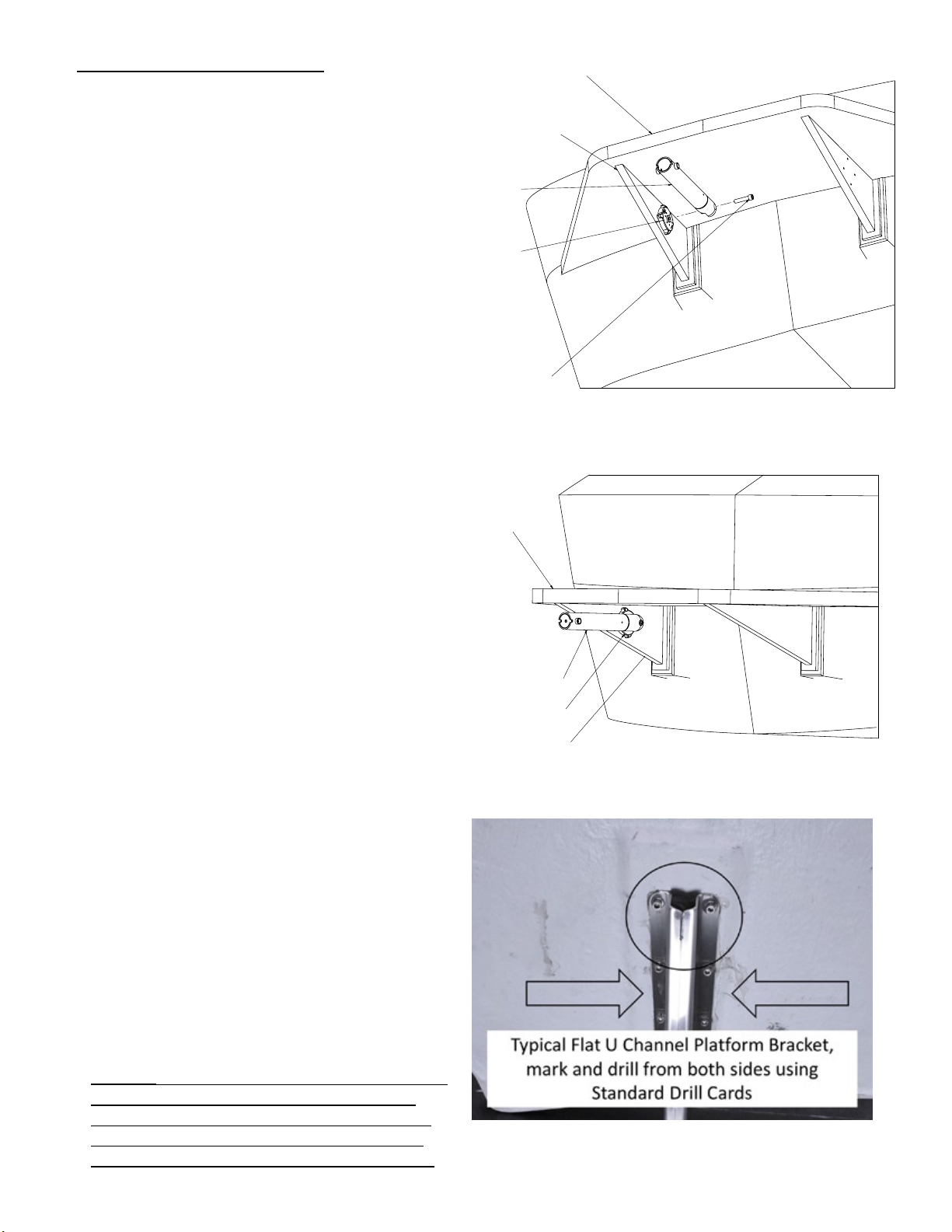
to align with the bottom of the platform.
It can be installed in any rotational
position provided it is the best t for
drilling holes. However, if your swim
step brackets are U-shaped (or hallow
in the middle) (Figure 10) and require
drilling from both sides, we recommend
“squaring up” the Flat Mount to the
bottom edge on the platform. This
will make it much easier to transfer
measurements to the other side. This
will be further explained in the next few
steps.
Step 4: Mark position. Once desired location of
the Flat Mount and Lower Tube Assembly is found
mark the clamp location on the swim platform
bracket. Remove the temporarily installed Lower
Tube Assembly from the Flat Mount at this time.
For the “U”-channel brackets proceed to Step 5. For
solid brackets, proceed to Step 7.
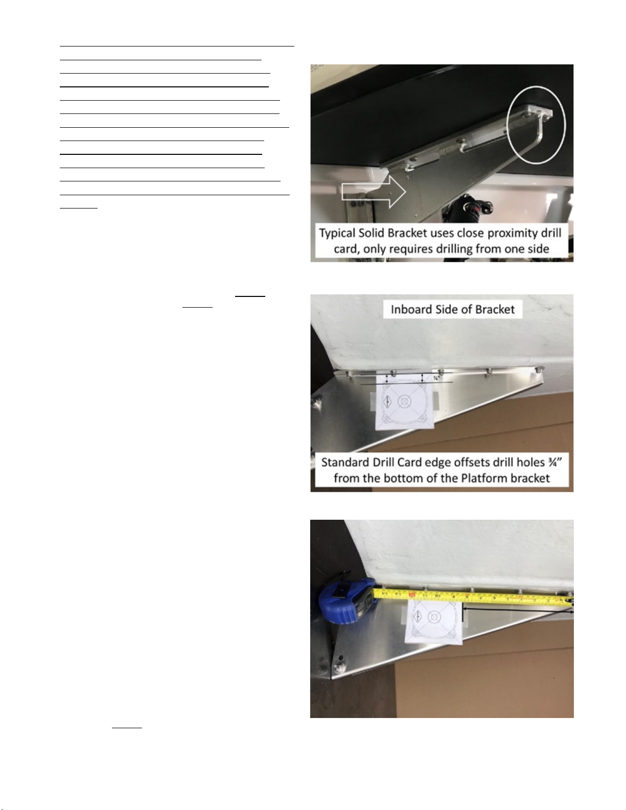
Step 5: U-Channel Drill Preparation. The next
two steps are necessary to properly drill through
the U-channel. Drilling this type of bracket will
require drilling holes from both sides to prevent
misaligned holes. Using the mark from Step 4,
place the Standard drill card on the marked side
of the swim platform bracket ensuring the top
edge is ush with the platform support edge as
shown in Figure 12. Temporarily tape the card
to the bracket in two places.
Note: Ensuring the card is ush to the bracket
support is important, the same sized card will be
placed on the opposing side of the bracket the
height must be the same to drill a straight hole.
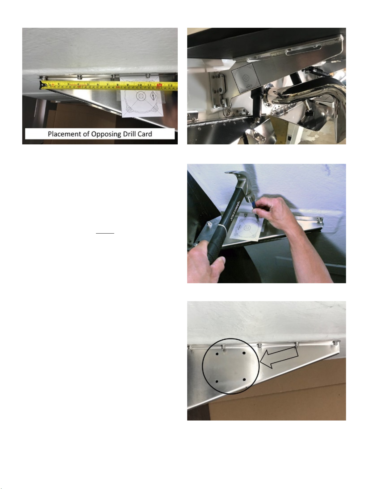
Step 6: Placement of opposing drill card.
Measure and record the distance from edge of the
drill card to the aft edge of the platform bracket.
See Figure 13.
Using the measurement recorded above, measure
and mark the same location on the opposing side
of the swim platform bracket. See Figure 14.
Place the second drill card in the marked location,
and temporarily tape the card to the bracket in
two places. This is a good time to double check
you work on both sides. See Figure 14.
Note: Ensuring the card is ush to the bottom
of the bracket support is important, the drill hole
must align with the opposing side to ensure a
straight hole.
Proceed to Step 8: Center Punch holes.
Solid Swim Step BracketFigure 11.
Standard Drill Card on U-Channel BracketFigure 12.
Measure Card Location to edge of BracketFigure 13.

Wake N Grill Page 8
Step 7: Solid bracket Drill Preparation. The next
steps are necessary to properly drill through the
solid bracket. The “Close Proximity Drill Card” is
supplied to outline the Minimum space required
for installation. The use of this card may be
necessary for situations where manufacturers use
removable swim steps or brackets with a smaller
footprint.
Using the mark from Step 4, place the Close
Proximity Drill Card on the marked side of the
swim platform bracket ensuring the drill holes
are within the solid portion of the swim platform
bracket. See Figure 15. Temporarily tape the
card to bracket in two places.
Step 8: Center Punch hole locations. Using
a Center punch and hammer, carefully locate
the center of each bolt hole (4 holes) using the
target cross-hairs on each bolt hole. Punch the
centers of each hole using a forceful hit with the
hammer. If the bracket is stainless steel you will
want to give it an extra punch. Inspect to make
sure a center punch hole is imprinted on the swim
platform from each hole location, then remove the
drill card(s). See Figure 16.
Step 9: Drill Holes. First, drill pilot holes using the
smaller of the two provided Drill Bits, size #29.
Drill all holes at this time. It’s not a race, this
may take some time and leverage depending on
the type and thickness of the material.
Note: For U-Channel brackets make sure to drill
both sides separately. The will be a total of 8
holes that need to be drilled if you have this type
of bracket.
Once all the pilot holes have been drilled, use the
provided larger 17/64” drill bit and drill all holes
to the nal size. Deburr the holes for a nice nish
using a deburring tool or bit. See Figure 17.
Repeat for opposite sideFigure 14. Close Proximity Card on Sole BracketFigure 15.
Center Punch Mounting Holes (x4)Figure 16.
Final 17/64” HolesFigure 17.

Wake N Grill Page 9
Note: For U-Channel brackets, check hole
alignment using mounting bolts to ensure proper
t before proceeding.
Step 10: Install Flat Mount. Install the Flat
Mount onto the swim platform bracket using (See
Figure 18):
Washers WNG-1/4 Flat (QTY 4)•
Nuts WNG-1/20-B-NUT (QTY 4)•
1/4”-20 X (1”, 1.25”, or 2”) Socket Head Cap •
Screws (QTY 4)
If multiple bolt sizes are provided in your kit, use
the best t length for your boat with at least 3
threads protruding beyond the nut. See Figure
19.
NOTE: The washers should be installed on the
nut side of the bolt between the nut and platform
bracket. See Figure 19.
Tighten all 4, 1/4”-20 Socket Cap Screws in a
cross pattern. Complete the tightening sequence
twice to ensure everything is properly seated.
Proceed to next section (Lower Tube Installation).
Flat Mount InstalledFigure 18.
Backside of Flat MountFigure 19.

Wake N Grill Page 10
Lower Tube Installation:
The following steps describe how to properly level
the lower tube, which ultimately sets the position
of the Wake N Grill. The goal here is to install
the lower tube parallel with the swim step. See
Figure 23. This is extremely important and
will ensure your hotdogs don’t roll o the grill.
Nobody likes waterdogs...well, except maybe
catsh.
Step 1: Inspect Joint Parts. Refer to Figure
20. Take notice of the position letters on both the
Universal Clamp, (WNG-UNI-CLAMP), and Lower
Mount Tube, (WNG-LWR-TB). These position
letters (A,B,C,D) correspond with the clocking
notches on the respective Hirth Joints (WNG-
HIRTH) when installed. There are a total of four
(4) unique combinations. Each combination of the
Position Letters will “clock” the Hirth joints to a
slightly dierent angle. When used in conjunction
with the adjustable Hirth Teeth, the adjustability
is almost endless and should allow you to properly
level the lower tube.
Please refer to the Hirth Joint Clocking Table
for possible combinations.
Hirth Clocking Table
Clamp Position
WNG-UNI-CLAMP
Lower Tube Position
WNG-LWR-TB
C A
C B
D A
D B
Step 2: Initial Joint Setup. Perform the following
steps to identify the correct hirth positioning for
your boat.
First, align one Hirth Joint with notch relative to
Position Con the Clamp. Temporarily install
using (3) 1/4”-20 x 5/8” Flat Cap Screws. See
Figure 21.
Next, align the second Hirth Joint with notch
relative to Position B on the Lower Tube.
Temporarily install using (3) 1/4”-20 x 5/8” Flat
Cap Screws. See Figure 21.
&ODPSV66
3RVLWLRQ/HWWHUV&'
+LUWK-RLQW
&ORFNLQJ1RWFK
/RZHU7XEH$VVHPEO\
3RVWLWLRQ/HWWHUV$%
Inspect Components for MarkingsFigure 20.
&ODPSV66
+LUWK-RLQW
&ORFNLQJ1RWFK
DOLJQHGZLWK
3RVLWLRQ&
[
[
)ODW+HDG
&DS6FUHZ
/RZHU7XEH$VVHPEO\
+LUWK-RLQW
&ORFNLQJ1RWFK
DOLJQHGZLWK
3RVLWLRQ%
[
[
)ODW+HDG
&DS6FUHZ
Align to Proper PositionsFigure 21.

Wake N Grill Page 11
Step 3: Position Lower Tube. Install the Lower
Tube onto the Clamp using (1) 1/2”-13 x 2-1/4”
Socket Head Cap Screw and hand tighten bolt.
Carefully rotate the Lower Arm assembly and
engage the Hirth teeth in the closest position
to make the lower tube parallel with the swim
platform. See Figure 22.
If needed, repeat steps (2-3) using dierent
position combinations in the clocking table until a
satisfactory level tube position is obtained. See
Figure 23.
HINT: To check actual position of Lower Tube,
pull down on the aft end of the tube to rotate
and “seat” the entire assembly to simulate an “as
used” position. This will remove any gaps from
built in tolerances of the parts.
NOTE: It may take multiple trials to gure out
the right combination for your boat, proceed with
the table of adjustments until the t is visually
satisfactory. Remember you will be oating in
constant motion, perfection is only noticeable on
shore, ballast can x the rest.
Step 4: Secure all Parts. Once a satisfactory
position of the Lower Tube is found, temporarily
remove the Lower Tube from Clamp to apply
Loctite to all fasteners.
Individually remove (3) 1/4”-20 x 5/8” Flat
Head Cap Screws from the Clamp hirth joint and
reinstall after applying Loctite 243 threadlocker
(included) to the threads. Tighten screws. See
Figure 21.
Individually remove (3) 1/4”-20 x 5/8” Flat Head
Cap Screws, from the lower tube hirth joint and
reinstall after applying Loctite 243 threadlocker
(included) to the threads. Tighten screws. See
Figure 21.
Apply Loctite 243 threadlocker (included) to the
threads of (1) 1/2”-13 x 2-1/4” Socket Head Cap
Screw. Install WNG-LWR-TB assembly onto the
WNG-UNI-CLAMP assembly and hand tighten the
bolt. Ensure the tube is in a satisfactory position
and then perform nal torque. (approx. 55 ft-lbs).
See Figure 22.
Step 5: Install Pull-Pin. Determine which side of
the lower tube is most convenient to reach from
the swim platform. The Pull-Pin (WNG-PULL-PIN)
can be installed on either side of the Lower Tube
threaded boss. See Figure 24.
Apply Loctite 243 threadlocker (included) to the
threads of Pull-Pin. Tighten using an adjustable
wrench on the ats of the Pull-Pin base. DO NOT
overtighten, it will damage the slide mechanism of
the pin.
Install Lower TubeFigure 22.
6ZLP6WHS
/RZHU7XEH
$VVHPEO\
3XOO3LQ
0D\EHPRXQWHG
RQRWKHUVLGH
7KUHDGHG%RVV
Lower Tube Parallel with Swim StepFigure 23.
/RZHU7XEH
$VVHPEO\
[
6RFNHW+HDG
&DS6FUHZ
8QLYHUVDO&ODPSV
Install Pull-PinFigure 24.

Wake N Grill Page 12
Assembly and Installation of the
Mid Arm:
Step 1: Locate Parts. Unwrap and inventory the
following parts in preparation for assembly:
Mid Arm Assembly (WNG-Mid-Arm)1.
1/4”-20 x 3/8” Smooth Head Cap Screws2.
(QTY 2)
Step 2: Position Mid-Arm. Pick two adjacent
holes and temporarily install the two Smooth
Head Cap Screws into the Mid-Arm Assembly
as shown in Figure 25. Hole position is not
important and will be adjusted in the following
steps. Install Mid-Arm Assembly into the Lower
Tube (WNG-LWR-TB) by pulling out the Pull-Pin
(WNG-PULL-PIN) and rotating 90 degrees to lock
in the open position. See Figure 25.
Slide the Mid-Arm Assembly into the Lower Tube
until the screw heads seat into the locating slots
on the Lower Tube. The depth (or overhang) can
be adjusted by moving the two smooth head Cap
screws to dierent positions within the range
of threaded holes located on the Mid-Arm tube.
Each position changes the depth by 1-1/2” (5
positions for a total range of 6”). See Figure 25
and 26.
HINT: Choose a position that will still provide
enough space on the swim platform once the grill
and cutting board are set up. This position can be
changed at any time o the water by moving the
Position Screws.
Once the desired position is found, remove the
two smooth head Cap Screws and reinstall after
applying Loctite 243 threadlocker (included).
Tighten screws. DO NOT overtighten.
Step3: Check Position. Test the new position
setting by sliding the Mid-Arm Assembly back into
the Lower Tube. The Pull-Pin should still be in the
open position (if not, pull and rotate the Pull-Pin
shaft 90 degrees to open).
Slide the WNG-Mid-Arm in until the screw heads
seat into the locating slots on the Lower Tube.
See Figure 26.
NOTE: The locating screws are necessary to
assist with blind installation on the water, they
must be installed for ease of use.
Rotate the Pull-Pin shaft 90 degrees to lock it
in the closed position to ensure the Mid-Arm is
locked into position with the Pull-Pin. Usually you
will feel or hear the pin engage into the hole of
the Mid-Arm.
Give the Mid-Arm a tug to make sure it is locked
in and cannot slide out of the Lower Arm.
HINT: Practice this procedure (Step 3) on dry
0LG$UP$VVHPEO\
6ZLP6WHS
/RZHU7XEH
$VVHPEO\
3XOO3LQ
3XOODQG7ZLVWWRORFNRXW
[
6PRRWK+HDG
[6+&6
$GMXVWDELOLW\
5DQJH
Install Pull PinFigure 25.
3XOO3LQ
3XOODQG7ZLVWWRORFNRXW
[
6PRRWK+HDG
[6+&6
/RFDWLQJ6ORW
Install Pull PinFigure 26.

Wake N Grill Page 13
land so it is easier when out on the water. You
should become familiar with the “feel” as you
probably won’t be able to visually see the pin
when the boat is in the water.
THIS COMPLETES ASSEMBLY OF THE UNIVERSAL KIT
Installation of Umbrella Arm (Op-
tional):
Step 1: Locate Parts. Unwrap and inventory the
following parts in preparation for assembly:
Umbrella Arm Assembly (WNG-Umb-Arm)1.
1/4”-20 X 3/4” Flat Head Cap Screws (QTY 2)2.
Step 2: Positioning Umbrella Arm. Locate the
three threaded accessory holes along the rear
edge on the underside of the Mounting plate,
WNG-GRL-PLT. These holes allow the Umbrella
Arm to be mounted extending to either the right
or left side of the grill depending on preference.
See Figure 27 “Optional” section.
Step 3: Secure Umbrella Arm. Apply Loctite 243
threadlocker (included) to the threads of (2) 1/4-
20” X ¾’ Flat Socket Cap Screws and install the
Umbrella Arm into the selected position on the
underside of the Mounting Plate. Tighten screws.
HINT: We suggest the Umbrella Arm be mounted
to the right side of the Grill Plate. This will
position the Arm on the same side as the grill
regulator and will allow more room inside the
storage bag for additional supplies.
THIS COMPLETES ASSEMBLY OF THE UMBRELLA ARM
[6RFNHW
+HDG&DS6FUHZ
8PEUHOOD$UP
[)ODW
+HDG&DS6FUHZ
;
8PEUHOOD3OXJ
[6SULQJ3LQ
),1
/2&:DVKHU
;
:Q*),1/2&
0RXQWLQJ3ODWH
[6RFNHW
+HDG&DS6FUHZ
*ULOO3OXJ
2SWLRQDO
Install Pull PinFigure 27.

Wake N Grill Page 14
Prepping Storage Bag for Use:
It’s time to get ready for the lake! But rst, you’ll
need to pack your storage bag. We won’t go into too
much detail here, as everyone has their own method
of packing and storing equipment in their boat. The
Wake N Grill Storage bag is capable of storing the
grill, cutting board, serving trays, propane, and other
accessories. There should be plenty of room. See
Figure 28.
Note: The Storage bag does not hold the L-shaped
Mid-Arm assembly (this part has it’s own Neoprene
Sleeve) and will need to be stored separately.
Deploying Wake N Grill for use:
Hopefully by this point, you’ll have your Wake N Grill
and accessories tucked away nicely in the supplied
Storage Bag. Don’t forget extra propane to cook for
all the hungry people waiting.
Step 1: Get Ready. Round up your grill kit from
wherever you decided to stow it, and let’s get
cookin’.
Storage Bag (WNG-Bag, Qty 1) containing:1.
Grill and Regulator (GRILL, QTY 1)2.
Cutting Board (WNG-CBRD, QTY 1)3.
Serving Tray (WNG-TRAY, QTY 1)4.
Multi-Tool (WNG-MULTI-TOOL, QTY 1)5.
Spatula (WNG-SPATULA *Optional*, QTY 1)6.
Neoprene Sleeve (WNG-MID-A-SLV, QTY 1) 7.
Mid-Arm Assembly (WNG-MID-ARM, QTY 1)8.
CAUTION: The Wake N Grill and associated
accessories are designed to deploy while the boat
is moored. Use of the product while underway can
cause damage or injury and is not covered under
warranty.
NOTE: We recommend practicing the
following steps while the boat is not
on the water to get familiar with how
to deploy and safely stow the Wake N
Grill. Practice until these steps become
quick and easy. Remember most of the
kit doesn’t oat, the best way to stop a
Wake N Grill from sinking is by properly
engaging the pull-pin in the next steps.
Step 2: Installing Mid-Arm. Remove the Mid-Arm
assembly from its neoprene sleeve. While holding
the Mid-Arm assembly, make your way to the
swim platform and try to remember where you
installed the lower tube and which side the Pull-
Pin is on. See Figure 29.
Reach under the swim platform to locate the Pull-
0LG$UP$VVHPEO\
6ZLP6WHS
/RZHU7XEH
$VVHPEO\
3XOO3LQ
3XOODQG7ZLVWWRORFNRXWORFNLQ
Storage Bag and ContentsFigure 28.
Install Mid-ArmFigure 29.

Wake N Grill Page 15
Pin on the Lower Tube. Pull and twist the Pull-Pin
shaft 90 degrees to lock in the open position.
Slide the Mid Arm Assembly into the Lower
Tube until the smooth screw heads seat into the
locating slots on the Lower Tube.
Again, twist the Pull-Pin 90 degrees and allow the
spring and shaft to return to its closed position.
The pin should seat on its own, if it does not,
push the pin rmly to fully seat it.
Step 3: Adjusting the grill position using the
Twist-Lock (WNG-TWST-LK). The height feature
allows the grill to be adjusted for comfortable
heights (seated or standing position e.g.). The
rotational feature allows the grill to be rotated and
locked in any position. This is especially useful
for maximizing grill position for optimal burger
slanging. See Figure 30.
Using the Multi-Tool (WNG-MULTI-TOOL) provided,
or optional Spatula (WNG-SPATULA), position the
tool over the grooves of the Twist-Lock. Slightly
turn counter-clockwise to loosen. See Figure 30.
Position the Upper Slide Tube assembly into the
desired position.
HINT: The upper tube Pull-Pin is designed to
align with the front of the grill. Whichever way
the logo on the pin faces, the front of the grill will
face also.
Again, using the Multi-Tool provided, or optional
Spatula, position over the grooves of the Twist-
Lock. Tighten by turning Twist-Lock clockwise.
Snug is good but snugger is better to keep the
position tight.
NOTE: Failure to properly snug the Twist-Lock
could result in a sudden height drop, most often
during a critical step in the cooking process. Use
your best judgment, but don’t go bananas and let
Goliath do it as it will be dicult to unlock or may
cause damage to the tools.
Step 3: Installing the Grill. Make sure the grill
lid is secured and locked so you don’t lose any
internal grill parts.
Pull and twist the upper Pull-Pin 90 degrees to
lock in the open position.
While holding the Grill by it’s handle, position Grill
assembly with both hands so that the Grill Plug
slides into the Upper Tube. Conrm Grill Plug is
fully seated into the Upper Tube. Twist the upper
Pull-Pin shaft 90 degrees to allow the shaft and
spring to return to its closed position. The pin
should seat into the Grill Plug groove on its own,
if it does not, push the pin rmly to fully seat it.
See Figure 31.
HINT: The Grill Plug has a safety groove that
allows the Pull-Pin to partially engage in any
position, preventing the grill from unintentionally
2SWLRQDO
6SDWXOD
0LG$UP$VVHPEO\
/RZHU7XEH$VVHPEO\
7ZLVW/RFN
2SWLRQDO6SDWXOD
0XOWL7RRO
0LG$UP$VVHPEO\
/RZHU7XEH
$VVHPEO\
3XOO3LQ
3XOODQG7ZLVWWRORFNRXWORFNLQ
*ULOO$VVHPEO\
*ULOO3OXJ
Tightening Twist_LockFigure 30.
Install Grill AssemblyFigure 31.

Wake N Grill Page 16
releasing from the Upper Tube. In addition, the
Grill Plug features a positioning hole to fully lock
the grill in rotational alignment with the Pull-Pin.
In this position, the Pull-Pin is fully engaged and
the Grill will become set in rotational position.
This is useful to prevent the grill from turning
when the Umbrella is deployed or absolute
rotational postitioning is desired. See Figure 32.
Step 4: Install Cutting Board. Position the
cutting board onto the Grill Plate by rst aligning
the Cutting Board bracket with the mating bracket
on the Grill Plate. Next, angle the Cutting Board
upwards and insert the rounded prole into the
Grill Plate bracket. Once engaged, the Cutting
Board can be lowered to fully engage and lock
into the Grill Plate bracket. See Figure 33.
Next, turn the Fin Lock over the top edge of the
Cutting Board. The lock will keep the cutting
board in the down position and prevent lifting.
HINT: Don’t forget the Fin Lock, those surfers
come out of nowhere and could ruin your lunch.
Reminder: Practice the above steps on land
until you are comfortable with the entire process.
Setting up the grill on the water should be a
simple process and a safe process.
Step 5: Fire up the Grill!! The following steps
should be performed in accordance with the grill
manufacturers instructions.
Install propane regulator (if removable) and
propane tank. Ignite the grill according to grill
manufacture’s instructions.
Pro Tip: Use the included tray to serve up some
grilled goodness to the masses. Most importantly,
have some fun.
THIS COMPLETES THE DEPLOYMENT OF THE WAKE N
GRILL.
Deploying/Stowing Umbrella (Op-
tional):
CAUTION: The Wake N Grill Umbrella is designed
to deploy while the boat is moored in calm
conditions. Use of the product while underway
or in windy conditions (even slightly windy) can
cause damage or injury and is not covered under
warranty.
Step 1: Remove the Umbrella (WNG-UMB) from its
case.
NOTE: Take care when removing the Umbrella from
it’s storage case when on the water. The Umbrella
stows in two peices and may come out of the bag
unpredictably....and end up a sh habitat.
Step 2: Deploy Umbrella. Insert the umbrella
$
6WHSD/LIWDQGLQVHUWFXWWLQJ
ERDUGLQWRFKDQQHORQJULOOSODWH
&ORVHXS9LHZ$
6WHSE/RZHU&XWWLQJ%RDUG
XQWLOVHDWHGDQGORFNHGLQWR
FKDQQHORQJULOOSODWH7KHQ
WXUQ)LQ/RFNDVVKRZQ
)LQ/RFN
*ULOO3OXJ
6DIHW\*URRYH
3RVLWLRQLQJ+ROH
Grill Plug Groove and HoleFigure 32.
Cutting Board InstallFigure 33.

Wake N Grill Page 17
inner tube into the outer tube and lock into place
using spring lock button. Open the umbrella and
lock in place.
Install the lower tube over the Unbrella Plug by
depressing the Unbrella Plug snap button. Align
the snap button with hole in the lower umbrella
tube to lock in place.
Step 3: Stow Umbrella. Simply reverse above
steps.
Stowing Wake N Grill:
CAUTION: The Grill and accessories should never be
stowed until they are cool to the touch. Stowing
hot items could result in injury and damage the
storage bag. Marine grills are designed to cool
very quicky, so please be patient before stowing.
If you’re thinking about it, it’s probably too hot.
Step 1: Remove Propane, Regulator, and
Cutting Board. Make sure the grill is turned o
(see manufacturer’s instructions) and properly
cooled. Remove propane tank and propane
regulator (if applicable) and stow items in Storage
Bag.
Twist the Fin Lock to stowed position and remove
cutting board by tilting upwards and lifting out.
Stow in Storage Bag.
HINT: Rinsing the cutting board now is a good
idea if you like clean things
Step 2: Remove Umbrella. If equipped remove
Umbrella (see Umbrella Stowing Section)
Step 3: Clean. Now is a great time to clean the
grill and the grease trap (below grill) prior to
removing, then close and lock lid.
While holding the Grill by it’s handle, pull and
twist the Pull-Pin shaft 90 degrees to lock it in the
open position. Remove Grill assembly from the
Mid-Arm by lifting the assembly upwards.
Stow Grill assembly in Storage Bag.
HINT: Best practice is to store the grill on its back
(Handle up, regulator side towards propane
pockets) with the Serving Tray underneath to
catch any grease or leftovers.
Step 4: Stow Mid-Arm. Using the Multi-Tool or
optional Spatula, loosen the Twist-Lock on the
Mid-Arm.
Lower the Upper Slide Tube to the lowest position
for storage, aiming the Pull-Pin inboard, hand
tighten the Twist-Lock.
Reach under the swim platform and pull and twist
the Pull-Pin shaft 90 degrees to lock in the open
position.
Remove the Mid-Arm assembly from the Lower
Tube by sliding the mid arm out of the tube
towards the rear of the boat. Place Mid-Arm
assembly into the neoprene sleeve and stow.
Mid-Arm Sleeve and Storage BagFigure 34.

Wake N Grill Page 18
Care and Maintenance
Periodic maintenance:
Wipe down surfaces with damp cloth. Soap and water may be used to clean. Avoid harsh chemicals as they•
will damage the painted/polished surfaces.
The bamboo cutting board should be oiled on a regular basis using food grade mineral oil, minor cracks may•
appear and are normal.
The bag and cases may be washed using soap and water and air dried prior to storage•
Twist-Lock (#WNG-TWST-LK) threads can be lubricated periodically with Dry Film Lubricant.•
All Mounting and bracket bolts should be check annually for looseness, tighten if necessary.•
5 Year Limited Warranty
We oer a 5 Year Warranty on our products along with a 30 day money-back guarantee. If you are not satised with
our products in any way, return the item and we will refund your money!
Warranty Information
Dukes Marketing L.L.C. (Wake N Grill) warrants to the original purchaser that this product will be free from defects
in material and workmanship under normal use for a period of ve (5) years from date of original purchase from
an authorized Wake N Grill dealer. See exclusions for specic items not covered or with limited warranty. Should
repair be necessary under this warranty for any reason due to a manufacturing defect or malfunction during the
warranty period, Wake N Grill will repair or replace (at its discretion) the defective product with equivalent product
at no charge. Discontinued products may be replaced with equivalent products. Any applicable implied warranties
are limited in duration to a period of the express warranty as provided herein beginning with the date of the original
purchase at retail, and no warranties, whether express or implied, shall apply to this product thereafter. This
warranty is limited to defects in material and workmanship, and it does not apply to loss or damage due to accident,
misuse or negligence, or any cause occurring after delivery to the original purchaser.
Warranty Claims
Defective merchandise must be returned to your local authorized Wake N Grill Dealer for warranty issues. To locate
an Authorized Dealer please email or call Wake N Grill direct. If the return of defective merchandise is necessary,
call Wake N Grill at (480) 686-3130 to obtain a Return Authorization (RA) number. Package all defective items in the
original container or in a suitable package that will prevent shipping damage, and return to:
Wake N Grill
134 E. Broadway Rd. #101
Mesa, AZ 85210
Warranty Exclusions:
The following items have a limited warranty:
Plastic components (1 year)1.
Bamboo Products (1 year, cracks resulting from misuse or improper care not covered)2.
Chrome nish (1 year)3.
Anodized nish (1 year)4.
This warranty is valid only if the product is used for the purpose for which it was designed.
Wake N Grill does not cover:
Damage resulting from negligence, misuse, or accident•
Items physically damaged due to abuse•
Freight damage or mishandling•
Items previously repaired by any unauthorized repair facility•
Items returned by unauthorized individuals or dealers•
Return shipping of non-defective items•
The cost of shipping product to Wake N Grill•
Installation slips and marks as a result of installation•
Normal wear-and-tear from use, storage, and transportation•
Damage caused by exposure to water and/or excessive heat•
Items damaged from cross-threading fasteners or improper installation tools and techniques.•
Damage resulting from items coming into contact with objects such as bridges, other boats, etc.•
Table of contents