Walaby HYBRID WATER SYSTEM 15 g/h User manual

1.
TRAITEMENT D’EAU NATUREL
POUR PISCINE ET SPA
OWNER’S MANUAL
MANUEL UTILISATEUR

2.
OWNER’S MANUAL
TRAITEMENT D’EAU NATUREL
POUR PISCINE ET SPA
This manual concerns the following
models :
Le présent manuel concerne les
modèles suivants :
HYBRID WATER SYSTEM 15 g/h
HYBRID WATER SYSTEM 22 g/h
HYBRID WATER SYSTEM 33 g/h
Please refer to the production calculator
to choose the appropriate device.
Se référer au calculateur de production
pour choisir le bon appareil.
MANUEL UTILISATEUR
SUMMARY :
P3. 1- PARTS IDENTIFICATION LIST
LISTE DE COLISAGE
P4. 2- PRECAUTIONS TO BE TAKEN BEFORE
INSTALLATION
PRÉCAUTIONS À PRENDRE AVANT INSTALLATION
P5. 3- INSTALLATION INSTRUCTIONS
INSTRUCTIONS DE MONTAGE
P6. 4- HYBRID WATER SYSTEM POWER PACK
HYBRID WATER SYSTEM BOITIER ÉLECTRONIQUE
P7. 5- POOL PREPARATION
PRÉPARATION PRÉALABLE DE LA PISCINE
P8. 6- STARTING HYBRID WATER SYSTEM
DÉMARRER HYBRID WATER SYSTEM
P10. 7- MAINTAINING THE POOL
L’ENTRETIEN DE LA PISCINE
P11. 8- CELL INFORMATIONS
INFORMATIONS SUR LA CELLULE
P11. 9- GENERAL QUESTIONS & TROUBLE-
SHOOTING
QUESTIONS FRÉQUENTES ET DYSFONCTIONNEMENTS
P13. 10- CUSTOMER RESPONSIBILITIES
RESPONSABILITÉS DE L’UTILISATEUR
P14. WARRANTY
GARANTIE
SOMMAIRE :

3.
1- PARTS IDENTIFICATION LIST
LISTE DE COLISAGE
1. POWERPACK
2. CELL
3. CELL HOUSING
4. O-RING
5. CAP
6. REDUCING BUSHES
x From 60mm to 50mm
x From 60mm to 63mm
7. CELL SENSOR (FLOW & GAS)
1. BOITIER ÉLECTRIQUE
2. CELLULE
3. LOGEMENT DE CELLULE
4. JOINT
5. CULOT
6. RÉDUCTIONS
x De 60mm à 50mm
x De 60mm à 63mm
7. DÉTECTEUR DE DÉBIT ET DE GAZ
1.
3.
4.5.7.
1.
2.
6.
6.

4.
Before carrying out the installation or
maintenance of this product, disconnect the
power supply.
Non-compliance to any of the dispositions hereby
contained may cause damage to persons or things
or the incorrect functioning and damage to parts of
the equipment.
WARNINGS
During the phase of installation of this product
verify that the power supply corresponds to what
is indicated on the label situated on the base of
the unit;
N.B : Verify the presence of all parts in the packing
and carefully read all of the Instructions Manual
before beginning installation of this product.
S’assurer que le produit est débranché avant de
commencer l’installation ou la maintenance.
Le non respect de ces dispositions peut
entraîner des dommages corporels, des dégâts
et le mauvais fonctionnement total ou partiel de
l’appareil.
MISE EN GARDE
Lors de l’installation de l’appareil, s’assurer que
l’alimentation électrique correspond à celle
indiquée sur l’étiquette située en bas de l’appareil.
NB : S’assurer que tous les éléments se trouvent
dans l’emballage et lire attentivement le Manuel
Utilisateur avant de commencer l’installation de
l’appareil.
2- PRECAUTIONS TO BE TAKEN BEFORE INSTALLATION
ATTENTION!!!
ATTENTION!!!
PRÉCAUTIONS À PRENDRE AVANT INSTALLATION

5.
3 - INSTALLATION INSTRUCTIONS
WARRANTY WILL BE VOID IF THE CELL IS NOT INSTALLED AS SPECIFIED.
LA GARANTIE SERA ANNULÉE SI LA CELLULE N’EST PAS INSTALLÉE COMME INDIQUÉ
INSTRUCTIONS DE MONTAGE
1. FILTRATION POWER SUPPLY
COFFRET ÉLECTRIQUE DE
FILTRATION
2. HYBRID WATER SYSTEM
HYBRID WATER SYSTEM
3. CELL (NOTE: HOW THE CELL
HAS BEEN PLUMBED IN.
REFER TO THE NEXT SECTION)
CELLULE (ATTENTION AU
SENS DE MONTAGE)
4. HEATER (NOTE : ALL
AUXILLIARY EQUIPMENT MUST
BE UPSTREAM OF THE CELL)
CHAUFFAGE (TOUS LES
AUXILIAIRES DOIVENT ÊTRE
PLACÉS AVANT)
5. FILTER
FILTRE
6. PUMP
POMPE
7. POOL
PISCINE
3.2 H.W.S CELL
Please refer to Figure 3.1, it is recommended to
install the electrolytic cell within 1.5 metres of a
vertical wall or fence to allow the power pack to
be easily mounted. The Cell must be installed
such that a localized air pocket will form in the
event that no water is flowing. Any heaters or
other equipment MUST be installed before the
cell. Also note that the flow sensor must always
be positioned above the cell (7) to function
effectively.
3.2 CELLULE D’ELECTROLYSE
Se référer au schéma 3.1. Il est recommandé
d’installer la cellule d’électrolyse dans un rayon
de 1,5m sur un mur vertical, de façon à simplifier
l’installation de l’alimentation. La cellule doit être
installée de façon à ce qu’une poche d’air puisse se
former dans l’éventualité où l’eau ne circulerait pas.
Les pompes à chaleur ou les autres équipements
doivent impérativement être installés avant la
cellule. A noter que les détecteurs de flux doivent
toujours être positionnés au-dessus de la cellule
pour fonctionner efficacement.
CELLULE
BACKWASH
ASPIRATION
COFFRET
ÉLECTRIQUE DE
FILTRATION
DÉTECTEUR
DE DÉBIT
TRAITEMENT D’EAU NATUREL
POUR PISCINE ET SPA
PISCINE
INVERSIONDEPOLARIT É
OFF ON
EAUCALCAIRE
PISCINECOUVERTE
IDEAL1000-2000PPM
P
R
O
D
U
C
T
I
O
N
EAU
CALCAIRE
FullColor Graphics with any clear windows shown in RED.
TRAITEMENT D’EAU NATUREL
POUR PISCINE ET SPA
Schéma d'installation
HYBRID WATER SYSTEM
WALABY
®
• 229, avenue de Saint-Médard • 33320 Eysines • technic@walabyconcept.com • www.walabyconcept.com
FLOW
DETECTOR/
SUCTION
LAVAGE
1.
2.
3.
4.
5.6.
7.
3.1 SCHÉMA
3.2 SCHÉMA

6.
4 - HYBRID WATER SYSTEM POWER PACK
HYBRID WATER SYSTEM BOÎTIER ÉLECTRIQUE
4.1 H.W.S POWER PACK
While the H.W.S. power pack has a UV resistant
cover, for optimum performance & lifespan, the
chlorinator should be installed out of direct sun
light & if installed within an enclosure, should
have reasonable ventilation. The power pack
must be mounted on a vertical wall or fence
within 1.5 metres of the cell and at least 1 metre
above the ground.
When connecting the cell, there are 3 connections
Anode (RED), Cathode (BLACK) & the Sensor
(WHITE). (Refer to following diagram in Figure 4.2).
4.1 BOITIER ELECTRIQUE H.W.S
Même si l’alimentation du H.W.S. a un revêtement
anti UV, il est recommandé de ne pas l’installer sous
la lumière directe du soleil afin d’avoir une durée
de vie plus longue et une performance optimale.
Si l’appareil est installé dans un local technique
enterré, s’assurer que la ventilation est suffisante.
Le système d’alimentation doit être installé sur un
mur vertical dans un rayon de 1,5m de la cellule et
au moins à 1 mètre du sol.
Pour connecter la cellule il y a 3 connexions : l’Anode
(rouge), la Cathode (noir) et le Sensor (détecteur de
debit) (blanc) – voir dessin ci dessous fig 4.2
To ensure that the pump is always running while
the H.W.S. is operating, the user has the option
of plugging the pump into the base of the H.W.S.
Once everything is securely plugged to the cell &
to the H.W.S., only then plug the power lead into
the 220-240 VAC power.
La pompe de filtration peut être asservie à H.W.S.
grâce au TIMER optionnel.
Une fois que tout a été branché en toute sécurité au
H.W.S. et à la cellule, brancher le câble d’alimentation
sur 220 – 240 V.
THE HYBRID WATER SYSTEM MUST BE RUN IN CONJUNCTION
WITH THE FILTER/PUMP AT ALL TIMES.
HYBRID WATER SYSTEM DOIT TOUJOURS ETRE ASSERVI A LA FILTRATION
Anode (ROUGE)
Cathode (NOIR)
DETECTEUR DE DÉBIT
Asservissement pompe filtration
(version européenne)
Fusible réarmable
Connexion volet roulant (version européenne)
4.2 SCHÉMA
4.2 SCHÉMA

7.
5 - POOL PREPARATION
PRÉPARATION PRÉALABLE DE LA PISCINE
5.1 CALCULATING SALT OR MAGNESIUM
REQUIREMENT
The H.W.S. has been designed to operate at
optimum TDS concentration from 1,2 g/l to 1,5 g/l.
Operating your pool at 1 g/l to 2 g/l is ideal and
will reduce the running time of your pump, filter
and also extend cell life.
According to the geographical area, the conductivity
of the water can vary, it is possible that you are
obliged to add 1 bag to obtain 10 leds on.
DO NOT attempt to add salt or Magnesium via
the skimmer as this can cause damage to the
filtration system and the H.W.S.
DO NOT have any automatic suction type pool
cleaners operating until the salt has completely
dissolved. Allow the salt to dissolve for 24 hours
before powering the system.
5.1 CALCUL DES BESOINS EN SEL OU EN
MAGNÉSIUM
Le système H.W.S a été conçu pour fonctionner avec
un taux de Sel ou Magnésium optimum de 1.2 g/l à
1,5 g/l.
La plage de concentration se situe entre 1 et 2 g/l.
A la mise en service 2 g/l sont nécessaires afin
d’atteindre 100% de production (cf 6.1, 10 leds
allumées).
Selon la zone géographique et la qualité d’eau, la
conductivité pouvant varier, vous serez peut-être
tenu d’ajouter 1 sac ou plus de Magnesium ou de sel
pour obtenir les 10 leds allumées.
Cette faible concentration dans l’eau permet de
réduire la durée de marche de la pompe, du filtre et
permet d’optimiser la durée de vie de la cellule.
NE PAS ESSAYER d’ajouter de Sel, ni Magnésium via
le skimmer, pouvant causer de graves dommages
au système de filtration et à la cellule.
NE PAS METTRE EN MARCHE un robot de piscine
quel qu’il soit, avant la dissolution totale du Sel ou du
Magnésium. Attendre 24h pour la dissolution totale
avant de mettre H.W.S. en production.
PLEASE REFER TO THE FRESH WATER GUIDELINES.
SE RÉFÉRER AU GUIDE POUR UNE EAU DOUCE.

8.
6 - STARTING HYBRID WATER SYSTEM
DÉMARRER HYBRID WATER SYSTEM
Before switching ON the H.W.S., making sure the
pump and H.W.S. are plugged into the power outlet.
Once the H.W.S. is switched ON, the Disinfectant
Production Output Display will show the disinfectant
production setting. By default, the unit should be set
to 100% & should not be changed during the initial
setup period. At this point, your H.W.S. will now
generate Disinfectant.
S’assurer que la pompe et l’appareil sont branchés
avant de mettre le système en marche. Une fois
que le système est en marche, l’affichage indiquera
le taux de production de désinfectant. Par défaut,
l’appareil est réglé sur 100%. HYBRID WATER
SYSTEM produit le désinfectant issu du Sel ou du
Magnésium et une eau douce.
THE HYBRID WATER SYSTEM MUST BE RUN IN CONJUNCTION
WITH THE FILTER/PUMP AT ALL TIMES.
HYBRID WATER SYSTEM DOIT TOUJOURS ETRE ASSERVI A LA FILTRATION
6.1 LED CONTROL PANEL & DISPLAY
6.1 PANNEAU DE CONTRÔLE À LEDS, ET
TOUCHES DE CONTRÔLE
PLEASE REFER TO THE FRESH WATER GUIDELINES.
SE RÉFÉRER AU GUIDE POUR UNE EAU DOUCE.
INVERSION DE POLARITÉ
OFF ON
EAU CALCAIRE
PISCINE COUVERTE
IDEAL 1000-2000 PPM
P
R
O
D
U
C
T
I
O
N
EAU
CALCAIRE
Full Color Graphics with any clear windows shown in RED.
A
BC
D
E
TRAITEMENT D’EAU NATUREL
POUR PISCINE ET SPA
F

9.
ON/OFF BUTTON
Main switch for the H.W.S.
OUTPUT DISPLAY
A series of 10 Led’s, which indicates the output
production level of the H.W.S. Each LED represents 10%
of the maximum output level the unit has been calibrated
to. Adjustment of the output level is performed using the
+ / - buttons (F). The output level should only be reduced
if an excess of desinfectant is being produced for the
required filtration time.
“POLARITY” LED
Indicates when the H.W.S. is in reverse polarity.
This LED will show that the H.W.S. changes polarity
periodically every 4 or 6 hours, depending on the
HIGH CALCIUM setting.
“HIGH CALCIUM” LED
Indicates when the H.W.S. is set to operate in a
HIGH calcium environment. Pressing the “CALCIUM
HIGH/LOW” button (D) changes this setting.
“POOL COVER” LED
Indicates when the system has detected the
connection of a pool cover. In that case production
will be reduced by 50%. We recommend an ORP
Regulation (optional), or a Fresh Intelligence module.
“+ OR -” CONTROL
Adjustment of the output level +/- %
Indicates when the system has detected the
connection of a pool cover. In that case production
will be reduced by 50%. We recommend an ORP
Regulation (optional), or a Fresh Intelligence module.
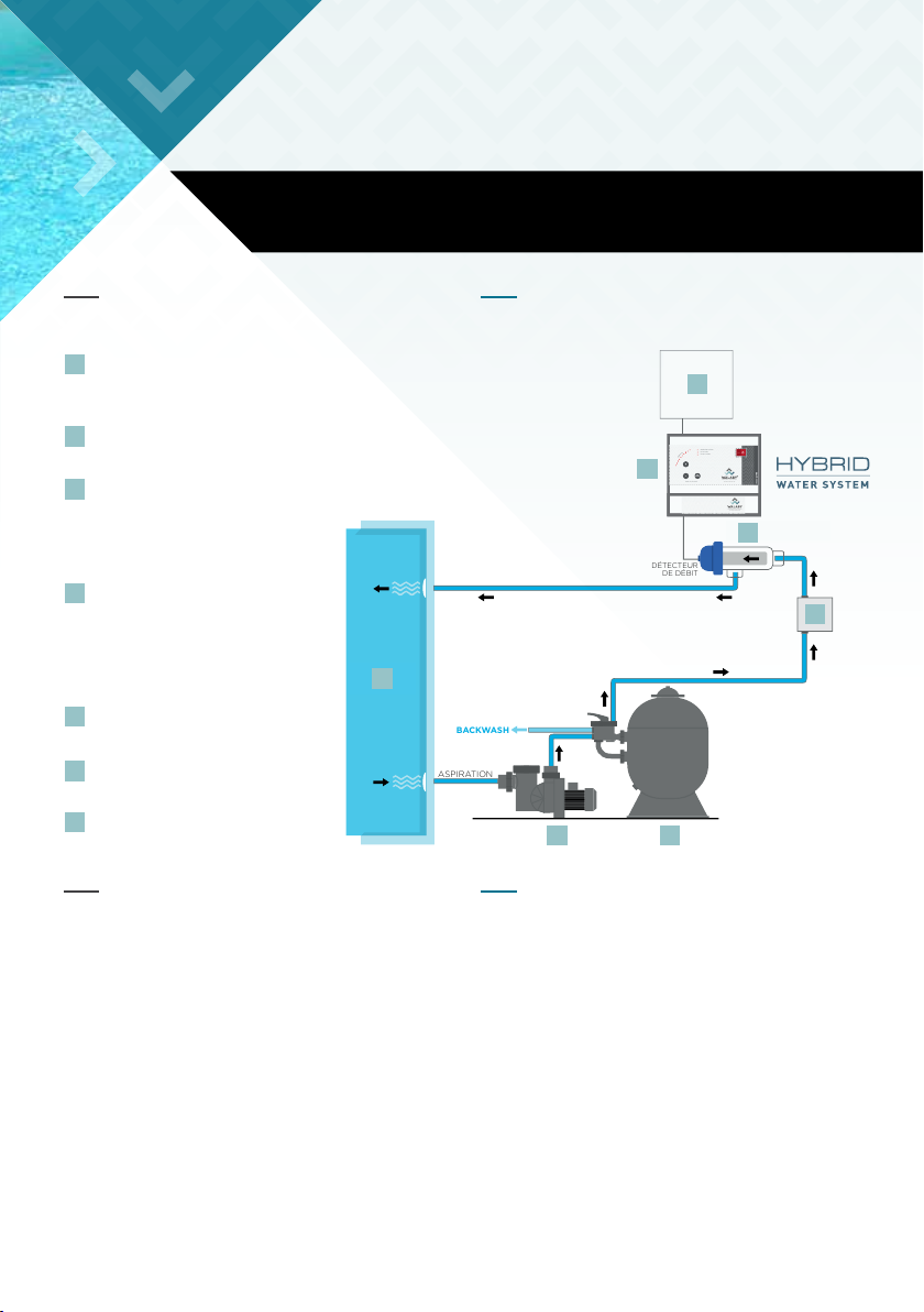
A simple to use timer can be used to control the
operating time of the HWS & pump for the filtration
system.
Une horloge de programmation peut être ajoutée en
option pour contrôler la durée de fonctionnement du
système.
6.2 TIMER
6.2 HORLOGE DE PROGRAMMATION
E
C
D
INTERRUPTEUR PRINCIPAL
Bouton d’alimentation du H.W.S.
AFFICHAGE DU NIVEAU DE PRODUCTION
Une série de 10 LEDS indique le niveau de production
de désinfectant. Chaque LED représente 10% du
niveau de production. L’ajustement du niveau de
production se fait à l’aide des boutons + /- (F).
VOYANT “INVERSION DE POLARITÉ”
Indique quand le système est en polarité inversée.
Cette LED montre que le système change de polarité
(toutes les 6 heures, ou 4 heures si le bouton “Eau
Calcaire” est activé).
VOYANT “HAUT CALCAIRE”
Indique quand le système est programmé sur
la fonction Eau Calcaire. Pour changer cette
programmation, appuyer sur le bouton “Eau
Calcaire” (D).
VOYANT “PISCINE COUVERTE”
Indique quand le système a détecté le
branchement d’un “contact sec” sur un volet
roulant par exemple. Dans ce cas il réduit de 50%
sa production. Nous conseillons une régulation
ORP (optionnelle), plus précise, ou le module
Fresh Intelligence.
VOYANT “+ OU -”
Bouton de réglage de production + ou –
Réglage de la production de désinfectant de 10%
en 10%.
A
B
F

10.
7 - MAINTAINING THE POOL
L’ENTRETIEN DE LA PISCINE
PLEASE REFER TO THE FRESH WATER GUIDELINES IN ANNEX, WHICH WILL BE GIVEN TO YOU
BY YOUR POOL SPECIALIST WHEN YOUR HYBRID WATER SYSTEM IS FIRST PUT INTO SERVICE.
VOIR GUIDE POUR UNE EAU DOUCE EN ANNEXE, QUI VOUS SERA REMIS PAR VOTRE
PISCINIER LORS DE LA MISE EN SERVICE DE VOTRE HYBRID WATER SYSTEM.
7.1 DESINFECTANT LEVEL
Using a 4 in 1 test kit, test the pool water at least
once a week to ensure a sufficient disinfectant level
is being maintained. Magnesium Hydroxyde or
Sodium Hypochlorite will be produced.
A chlorine reading of 1.5 mg/l (1.5 PPM) and above
is adequate when taken near the skimmer box.
Should the level fall below 1.5mg/l, check the salt
or Magnesium level to ensure it is correct; increase
the production level if not 100%; & if this isn’t
sufficient, increase the daily running time for the
H.W.S., pump & filter.
7.1 TAUX DE DESINFECTANT
Tester l’eau de la piscine régulièrement pour
s’assurer du niveau de désinfectant (lecteure chlore,
pastilles DPD 1) soit maintenu.
Pour une mesure prise près du skimmer, le niveau
d’hydroxyde de Magnésium ou d’hypochlorite de
sodium (lecture chlore) doit être au minimum de
1.5mg/l.
Si le niveau descend en dessous de 1.5mg/l,
s’assurer que le niveau de Magnésium ou de Sel est
suffisant. Augmenter la production si le niveau n’est
pas à 100%. Si cela est insuffisant, augmenter la
durée de fonctionnement du système, de la pompe
et du filtre.
76.2 PH LEVEL
The correct pH is within the range of 6.8 to 7.2 for
fibreglass pools and 7.2 to 7.6 for other pools.
7.2 NIVEAU DE PH
Le niveau de pH se situe entre 6.8 et 7.2 pour les
piscines en fibre de verre et entre 7.2 et 7.6 pour les
autres piscines.
7.3 TOTAL ALKALINITY
TA should be checked at least once every month
and should be maintained between 120 to 150 mg/l
(120PPM to 150PPM) for correct pool water balance.
Have the water checked for Cynuric Acid Stabiliser.
7.3 ALCALINITÉ TOTALE
L’ Alcalinité Totale doit être vérifiée au moins une fois
par mois et doit être maintenue entre 120 et 150 mg/l
(entre 120ppm / 150ppm) pour un bon équilibre de l’eau.
Vérifier le taux de stabilisant dans votre eau de piscine.

11.
WARRANTY IS VOIDED IF ANY OF THE ABOVE IS FOUND TO BE CASE.
LA GARANTIE SERA ANNULÉE SI L’UNE DES CONDITIONS CI-DESSUS EST REMPLIE.
9.1 HOW DOES H.W.S WORK?
The H.W.S. works by utilising the salt or Magnesium
in the water which is made up of Sodium & Chlorine
(NaCl) OR Magnesium and chlorine (MgCl2). The
H.W.S. supplies current to the cell which, in the
presences of the catalyst coating, promotes specific
reactions those results in Sodium Hypochlorite OR
Magnesium Hydroxyde and Oxygène. This kills
bacteria & in doing so, brakes down back to salt or
Magnesium.
9.1 COMMENT MARCHE H.W.S ?
Le système fonctionne en utilisant du Sel ou du
Magnésium ajouté et dissous dans l’eau. Le système
fournit du courant à la cellule et aux électrodes
dont la technologie spécifique transforme le Sel
en Hyprochlorite de Sodium et le Chlorure de
Magnésium en Hydroxyde de Magnésium. Ces 2
désinfectants ont un effet bactéricide et algicide et
apportent la rémanence à l’eau de votre piscine.
9.2 HOW DOES THE SELF-
CLEANING H.W.S. WORK?
Usualy, the H.W.S. operation is the same as the
standard Chlorinator. The H.W.S. Cell cleans itself
when the polarity is reversed. In the Standard
Cell, Calcium builds up over a period of time
depending on how much calcium the pool contains.
White Cement pool finishes are known to have a
calcium problem and a Self-Cleaning Chlorinator
is an option to eliminate frequent cleaning of the
chlorinator cell. Note: Chlorine or disinfectant is
produced in both polarities.
9.2 COMMENT L’AUTO-NETTOYAGE
DU SYSTEME FONCTIONNE ?
La cellule est auto-nettoyante grâce à une inversion
de polarité. Toutes les 6 heures de série. Si le bouton
“Eau Calcaire” est activé, l’inversion se fera toutes
les 4 heures. Note : Le Désinfectant est produit
quelque soit le sens de polarité.
8 - CELL INFORMATIONS
9 - GENERAL QUESTIONS & TROUBLE-SHOOTING
INFORMATIONS SUR LA CELLULE
QUESTIONS FREQUENTES & DYSFONCTIONNEMENTS
The cell should be periodically inspected for
accumulations of any foreign deposits. Common
Causes of Premature Cell Failure:
• Operating the cell with too little salt or
Magnesium in the water.
• Excessive accumulation of calcium deposits on
the cell.
• Low water through cell.
• Damage to electrode coating caused by scraping
with sharp object.
• Cleaning the cell in too strong an acid solution.
• Acid washing the cell for too long and too often.
La cellule doit être inspectée périodiquement afin
de vérifier les accumulations de dépôts.
Les causes principales du remplacement de cellule
sont les suivantes :
• Fonctionnement de la cellule avec trop peu de
Sel ou de Magnésium.
• Accumulation excessive de calcium dans la
cellule, sur les électrodes.
• Niveau d’eau trop bas dans la cellule.
• Dommages mécaniques causés sur l’électrode.
• Nettoyage intensif de la cellule avec de l’acide.

12.
9.3 FUSE
This model of chlorinator comes with a resettable
fuse, located as shown in Figure 4.2. Pressing the
red button can reset the fuse. If the fuse is unable
to be reset, turn off the power to the unit, unplug it
& call an authorized service technician.
9.3 FUSIBLE
Ce modèle est accompagné d’un fusible réinitialisable
comme l’indique le schéma 4.2. Pour réinitialiser le
fusible appuyer sur le bouton rouge. Si le fusible ne
se réinitialise pas, couper le courant, débrancher et
appeler un technicien.
9.4 LOW DISINFECTANT PRODUCTION
Please refer to section “7.1 disinfectant Level”. One
possible reason for low disinfectant production
is low salt or Magnesium level. If this occurs, the
display will show a level lower than that set and
the user will also be unable to raise the level. Salt
or Magnesium will need to be added, following the
procedure set out in section 5.1 Calculating Salt /
Magnesium Requirement.
It should be noted that generally pool will not
normally lose Salts. Warm weather generally
makes the water evaporate, raising the salt or
Magnesium level. But high rain fall can dilute
the pool water reducing the salt or Magnesium
concentration.
Another possible reason for this problem is that the
H.W.S. is under-capacity. Generally, chlorinator’s
capacity is specified by pool sizes for warm & cool
climates. But this assumes a concentration of
people per day & this can take a chlorinator beyond
its limit, if exceeded.
H.W.S. is a technique based on a low and regular
“no chemical chlorine” production, it is not
unusual as you can have a visually perfect water
to measure low or no chlorine level.
9.4 PRODUCTION FAIBLE DE DESINFECTANT
Se référer à la section 7.1 “ Taux de désinfectant”. La
faible production de désinfectant est due à un faible
niveau de Sel ou de Magnésium. Si cela se produit,
l’affichage montrera un niveau qui est plus bas que
celui déterminé préalablement. L’ajout de Sel ou de
Magnésium est nécessaire selon la procédure de la
section 5.1.
A noter qu’une piscine ne perd généralement pas
de Sel ou de Magnésium. L’eau s’évapore lorsque la
température est élevée ou lorsque la différence de
température entre le jour et la nuit est importante. De
fortes précipitations peuvent diluer l’eau de la piscine
conduisant à une réduction de la concentration en Sel
ou Magnésium.
Un système sous dimensionné peut aussi être en
cause. En règle générale, la capacité du système est
définie par la taille de la piscine, la température de
l’eau, le nombre de baigneurs, le temps de filtration
pour les climats chauds ou tempérés. Si ces critères
ne sont pas pris en compte un système pourra être
amené à fonctionner au-delà de sa limite.
H.W.S. étant une technique basée sur une production
faible et continue de « chlore non chimique », il n’est
pas rare de constater visuellement une eau parfaite
et de mesurer une taux de chlore faible ou nul.
WARNING: THERE ARE NO USER-SERVICEABLE PARTS INSIDE CHLORINATOR
HOUSING. TO PREVENT ELECTRIC SHOCK, DO NOT REMOVE COVER
ATTENTION : LE BOITIER HYBRID WATER SYSTEM NE CONTIENT AUCUNE
PIECE DE RECHANGE POUR LE CLIENT PARTICULIER.
POUR PREVENIR LES RISQUES D’ELECTROCUTION, NE PAS RETIRER LE CAPOT.

13.
10 - CUSTOMER RESPONSIBILITIES
RESPONSABILITES DE L’UTILISATEUR
Before you call for service please read the Operating
Instructions carefully and check through the
following points regarding your responsibilities
as customer. A service fee will be charged should
service be required as a result of any of the following:
Avant d’appeler un technicien, lire attentivement
les Instructions de marche et vérifier les points
suivants :
1. POWER POINT NOT TURNED ON.
2. FAULTY POWER-POINT
3. TIME CLOCK SET INCORRECTLY
4. UNIT INCORRECTLY INSTALLED.
5. POOR WATER CHEMISTRY (SALT, PH ETC).
6. CELL NOT MAINTAINED
7. WATER FLOW TOO LOW
8. UNIT HAVING BEEN TAMPERED
WITH BY UNAUTHORIZED PERSONS.
1. L’APPAREIL N’EST PAS SOUS TENSION
2. LE RÉSEAU ÉLECTRIQUE DOMESTIQUE EST
DÉFECTUEUX
3. L’HORLOGE N’EST PAS À L’HEURE
4. L’APPAREIL N’EST PAS INSTALLÉ COMME
PRÉCONISÉ.
5. LES VALEURS DE L’EAU (pH, Mg, SEL, TAC, CHLORE…)
NE SONT PAS CONFORMES.
6. MAUVAIS ENTRETIEN DE LA CELLULE.
7. DÉBIT D’EAU TROP FAIBLE.
8. L’APPAREIL A ÉTÉ MANIPULÉ PAR DU PERSONNEL
NON HABILITÉ.

WARRANTY
GARANTIE
WARRANTY IS IMMEDIATELY VOIDED UNDER THE
FOLLOWING CIRCUMSTANCE:
• Installation performed in-correctly by an un-
authorized person;
• Power Pack, or cell, serviced by an un-
authorized person;
• Correct TDS level not maintained at all times
(sodium or Magnesium), please check Fresh
Water Guidelines;
• Power Pack not protected from the elements,
or not operated with adequate ventilation;
• Cell not correctly maintained, or water flow too
low.
This warranty is only applicable to material &
workmanship only. It is non-transferable & doesn’t
cover freight cost. UNDER NO CIRCUMSTANCE
will we take responsibility for loss, damage to
property or, injury to person(s) due to a failure of
this equipment or installation. This warranty shall
not extent to any cost otherwise incurred.
LA GARANTIE SERA ANNULÉE SI L’UNE DES
CAUSES SUIVANTES EST AVÉRÉE :
• Installation non conforme réalisée par une personne
non habilitée ;
• Module de puissance, ou cellule, dépanné par une
personne non habilitée ;
• Un niveau de Sel ou de Magnésium non maintenu au
niveau optimum (voir Guide pour une Eau Douce) ;
• Module de puissance non protégé contre les
éléments climatiques ou électriques, ou installé
dans un local technique avec une mauvaise
ventilation ;
• Défaut de maintenance de la cellule ou débit d’eau
trop faible.
Cette garantie est applicable uniquement sur le
matériel et la fabrication seulement. Il est non
transférable et ne couvre pas le coût du frêt. En
aucun cas, nous ne prenons la responsabilité pour les
pertes, dommages à la propriété ou dommage à la
personne (s) en raison d’une panne de cet équipement
ou de l’installation. Cette garantie ne s’étend pas sur
d’autres coûts éventuels.
This product has been produced & thoroughly
tested to the highest standard & therefore carries
the following warranty.
Both power Pack & cell have respectively 2 years
and 5 years full warranty, from date of purchase,
entitling the purchaser to have the product
repaired, or replaced, if shown to have failed due to
workmanship or materials.
Ce produit a été fabriqué et testé selon les standards
les plus élevés et est donc couvert par la garantie
suivante.
Le Module de Puissance & la cellule ont une garantie
complète respectivement de 2 ans et 5 ans pour
un usage particulier, à partir de la date d’achat,
donnant droit à l’acheteur d’avoir le produit réparé ou
remplacé, si démontré que la cause vient d’un défaut
de fabrication.
14.

PURCHASER’S NAME/
NOM DU CLIENT
ADRESS/
ADRESSE
PURCHASED FROM/
NOM DU REVENDEUR
DATE OF PURCHASE/
DATE D’ACHAT
MODEL/
MODÈLE
SERIAL N°/
N° DE SÉRIE
BUYER INFORMATIONS
INFORMATIONS ACHETEUR
THIS SECTION MUST BE FILLED OUT ON PURCHASE TO VALIDATE WARRANTY.
CETTE SECTION DOIT ÊTRE REMPLIE À L’ACHAT POUR VALIDER LA GARANTIE.

WALABY
229, avenue de Saint-Médard - 33320 Eysines
sav@walabyconcept.com
www.walabyconcept.com
TRAITEMENT D’EAU NATUREL
POUR PISCINE ET SPA
This manual suits for next models
2
Table of contents
Popular Water System manuals by other brands

POBEL
POBEL DETA 0040 quick start guide

RainWater
RainWater Mains Backup in a Box installation guide

AmeriWater
AmeriWater 20-3021 Operation manual

Tollco
Tollco WaterFuse Apartment User's manual & installation instructions

Aqualife
Aqualife ROYAL SODA instruction manual

Everpure
Everpure Opaque Housing A-20 20 Specification sheet

Spectra Watermakers
Spectra Watermakers Cape Horn Extreme 330R Installation and operating manual

Condair
Condair RO-A Service manual

GRE
GRE SIMPLEO 120 AR2085 Installation and maintenance manual

Watts
Watts 909 Series INSTRUCTION, INSTALLATION, MAINTENANCE AND REPAIR MANUAL

Viega
Viega PureFlow installation manual

GEP
GEP Breaky 1 installation manual