Wanco WI6000 User manual

Inverter Series Generator
Operator Manual
Model WI6000
May 2017 P/N 220884 Rev. A


Page | 1
PREFACE
Thank you for purchasing a Wanco portable inverter generator set. This manual contains important
safety and operating information - please read the complete manualbefore attempting to operate
the generator.
All information in this publication is based on the latest product information available at the time of
approval for printing. We reserve the right to make changes atany time without notice.
No part of this publication may be reproduced without written permission.
Throughout this manual pay special attention to statements preceded by the following signal
words:
Failure to properly follow these precautions is likely to result in
property damage, serious injury or death
Failure to properly follow these precautions can result in property
damage, serious injury or death
Indicates a possibility of personal injury or equipment damage if
instructions are not followed
Gives helpful information.
If you need assistance with your generator set, please contact our service department:
Wanco Inc.
5870 Tennyson Street
Arvada, Colorado 80003
303-427-5700
fax 303-427-5725
www.wanco.com

Page | 2

Page | 3
CONTENTS
1. SAFETY INSTRUCTIONS ..........................................4
2. UNBOXING AND ASSEMBLY....................................6
3. COMPONENT LOCATIONS.......................................7
4. PRE-OPERATION CHECK.......................................10
5. GENERATOR USE...................................................12
6. MAINTENANCE........................................................17
7. TRANSPORTING/STORAGE ...................................19
8. TROUBLESHOOTING..............................................20
9. SPECIFICATIONS....................................................21
10.WIRING DIAGRAMS.................................................22
Read and understand this Operator Manual before starting the generator.
Failure to do so could result in personal injury or equipment damage

Page | 4
SAFETY INSTRUCTIONS
Exhaust gas contains invisible but poisonous carbon monoxide. Never run the generator in an
enclosed area.
Gasoline vaporis invisible butextremely flammable andexplosive under certain conditions. Shut the
engine OFF and allow the generator to cool for two minutes before refueling. Never refuel while the
engine is running.
Keep away from smoking materials, sparks and other sources of combustion when refueling the
generator.
Neverattemptto“backfeed”orpowerabuildingthroughaninstalledreceptacle.Backfeedingcreates
a dangerous shock hazard for the user and for utility personnel working on power lines.

Page | 5
Engine exhaust is very hot. Place the generator at least three feet or one meter away from buildings
or other equipment during operation.
The muffler becomes very hot during operation and remains hot for several minutes after stopping
the engine. Be careful not to touch the muffler while it is hot.
Let the engine cool before storing the generator indoors.
Always make a pre-operation inspection before you start the engine.
Operate the generator on a level surface to prevent fuel spillage or oil starvation.
Know how to stop the generator quickly and understand operation of all controls.
Never permit anyone to operate the generator without proper instructions. Keep children and pets
away from the generator when it is in operation.
Do not operate the generator in rain or snow and do not operate when wet.
Page | 6
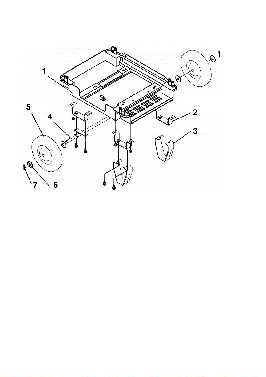
UNBOXING AND ASSEMBLY
1. WI6000H Chassis- installed
2. Support Bracket- (4)
3. Front Stabilizer (2)
4. AxleAssembly
5. 10” Wheel
6. Wheel Washer (4)
7. Wheel Clip
Assembly:
Install the four support brackets and secure with bolts.
Attach the front stabilizers to the chassis (below the handles)
Attach the axle assembly.
Install one washer on the axle against each welded stop.
Install the two wheels.
Install the two remaining washers and secure with the wheel clips.
The handles are preassembled before packaging. To raise the handles, simply raise the handle
assemblyto a horizontal position.To retract the handles,slidethechrome collars toward you toclear
the sleeve and lower them to the starting position.
Page | 7
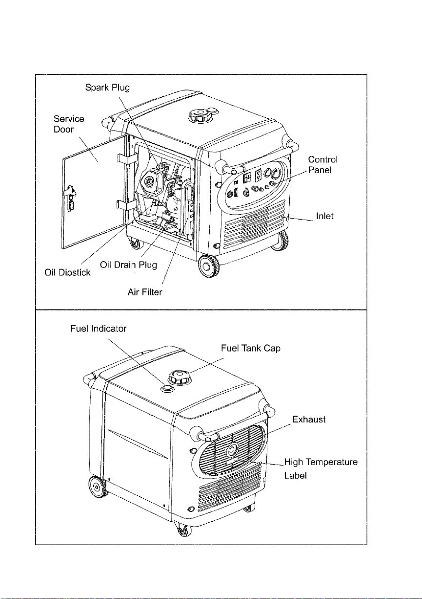
COMPONENT LOCATIONS

Page | 8
Control Panel
OUTPUT
INDICATOR
THERMAL
CIRCUIT
BREAKERS
SMART
THROTTLE
HOURMETE
R
CHOKE
START
SWITCH
GFCI
RECEPTACLES
DC RECEPTACLE
LOCKING
RECEPTACLE
GROUND
LUG
VOLTAGE
SELECT
SWITCH
OVERLOAD
RESET
SWITCH FUEL VALVE
Table of contents


