W&H 206 User manual

W&H MODEL 206 MOLDER
OWNERS MANUAL
WILLIAMS & HUSSEY
MACHINE CO.
www.williamsnhussey.com

1
OUR PLEDGE TO YOU
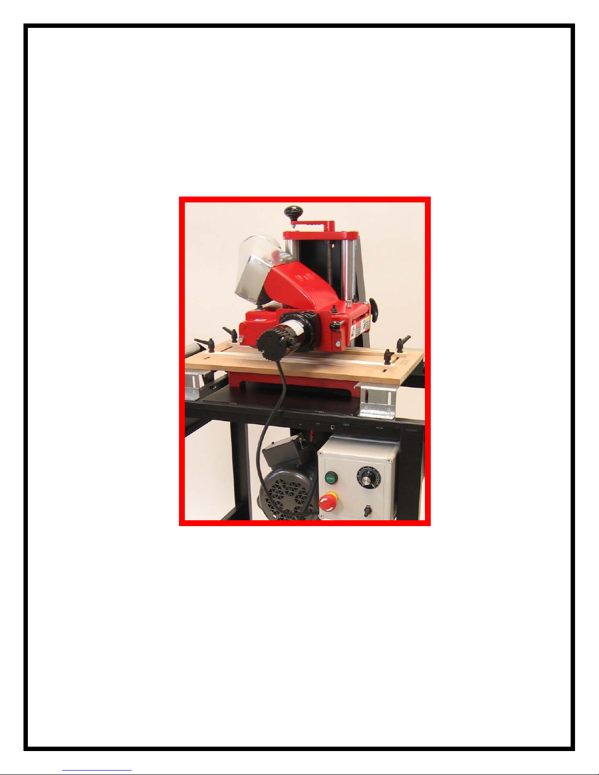
Your W&H Model 206 is a quality product and is built to last. Our technical support
services are legendary. Call us toll free. We are ready to help you with any maintenance
or operational questions you may have.
The Model 206 is a new design built in the W&H tradition of ruggedness and durability.
This machine rises above others in its class, in ease of use, compactness, versatility, and
the control over your work that you desire.
Knife changing is so simple that it can be perfectly done in about two minutes, allowing
you to quickly move from job to job.
The machine is manufactured in New Hampshire by people who take pride in making a
superior product. We welcome comments and observations from you on any aspect of the
machine and what you are making with it.
WILLIAMS & HUSSEY MACHINE CO. INC.
70 Powers Street
Milford NH 03055
Or see http://www.williamsnhussey.com
1800 258 1380 603 732 2019 fax 603 732 4048
Customer Service is available Monday-Friday, 8:30 AM- 4:30 PM EST
Complete Revision 6/91
Revised: 12/92
8/95
8/96
6/97
3/03
9/03
10/06

2
TABLE OF CONTENTS
In alphabetical order
SUBJECT PAGE
Assemble stand, motor, switch, and machine 3-10
Arbor in machine head illustration 40
Chatter 32
Feeding problems 34
Feed roller change 38
Feed unit removal 39
Guide system (GS1) installation 12-13
Guide system (GS1) operation 14-16
Guides 26-27
Knife changing/installation 22
Knife sharpening 23
Machine parts illustration 39
Molding 24-25
Parts list 35-36
Picture frames 27
Planing 31
Preparing to use the machine 19
Raised panels 29-30
Roller pressure 25
Round tops 28-29
Safety rules/check list 17-18
Snipe 33
Specifications 21
Sub-Plates 24
Thread locking 37
Vari-Feed operational tips 20
Warranty 41
Wire motor 11-12

3
ASSEMBLY OF YOUR PACKAGE PIECES
Stand parts
1. Fabricated main frame
2. Belt guard
3. belt guard attaching bracket
4. Solid wheels (2)
5. Caster wheel
6. Brake knobs (2)
7. Left hand roller brackets (2)
8. Right hand roller brackets (2)
9. Stock rollers (2)
Hardware
1. #10 screws and lock washers (2)
2. ¼” x 5/8” round head screws (15)
3. ¼” lock washers (19)
4. ¼” nuts (12)
5. ¼” flat washers (3)
6. ¼” x 1 ½” hex head bolts (4)
7. 5/16” x ¾” bolts, nuts, flat washers, and lock washers (4)
8. 3/8” x 2 ¼” axle bolts, flat washers, lock washers and nuts (2)
ASSEMBLY INSTRUCTIONS
Tools needed
Wrench 7/16”---------------Philips screw driver
Wrench ½”------------------Pliers
Wrenches 9/16” (2)--------Razor knife
Blade screw driver---------Wire stripper/crimper
Approximate time to assemble machine package is 3 hours.

Place solid wheels in the channel of the
bottom of the roller stand. Insert the
3/8”x 2 ¼” axle bolts through the holes
provided.
Install the flat washer, lock washer, nut
and tighten.
Install brake knobs in threaded insert on
end of the stand.
Mount castor wheel on its base with
(4) 1/4”x 5/8” round head machine
screws, lock washers, and nuts.
4

Mount the motor on the mount with (4)
5/16” x ¾” long bolts, flat washers, lock
washers and nuts. Do not tighten yet. The
motor is mounted with the shaft end in line
with the cut out for the belt in the machine
mounting area.
Mount the pulley on the motor
shaft
Place the machine on the stand with the pulley
side of the machine over the belt cut out area in
the stand.
5

Bolt the machine base to the stand using
(4) ¼ x 1 ½” long hex head bolts and lock
washers. Use the nuts that held the
machine to its shipping pallet.
6
Install the belt from the machine to the motor

Offset the motor within the clearance of the
elongated slots to find a running position that puts
the motor on the same plane as the bed of the
machine
Align the belt so that the belt travels in a straight line from one pulley to the
other.
Install the belt guard
bracket. Use (2) 10-24 x ½”
screws and lock washers.
7
Take the belt guard and mount it
over the top of the bracket and just
start a ¼” x 5/8” round head screw
with a flat washer in threaded hole
in the bracket.

Lift the guard slightly and start the (2)
lower ¼”x 5/8” round head screws
with flat washers. Tighten all three
guard screws
Mount the vertical
roller support brackets
in pairs, left and right
hand on both ends of
the stand. Use ¼”x 5/8”
long round head
screws, lock washers
and nuts.
The rollers are spring loaded. One end
depresses to allow you to engage the roller in
its set of brackets.
8

Install the two external stock rollers.
Your machine has been
packed with two control
mounting braces and
two #10 flat head
screws, lock washers
and nuts. They are
packed in the box under
the machine head. The
brace shown here is
being mounted to the
top of the black sheet
metal control mounting
enclosure. Use one of
the flat head #10
screws, lock washers
and nuts to mount the
brace on the inside of the sheet metal enclosure with the center counter sunk
hole facing you. The flat head screw goes into the center counter sunk hole. The
lock washer and nut go on the outside, or back side of the enclosure.
9
This view shows the second brace being
mounted to the bottom of the control
mounting enclosure. Use the one remaining
#10 flat head screw, washer and nut mounted
in the center hole of the bracket as you did
with the first brace.

Both braces are shown here
mounted to the control
enclosure.
The deluxe motor control gets
fastened to the enclosure with the
four “plastite” screws packed in the
box under the head of the molder.
These “plastite” screws go in the
four remaining open holes in the
brackets. Start each of the screws
and then tighten. Do not
overtighten.
The Vari-Feed motor plugs into the center of the
bottom of your control. Plug it in and twist it ¼ of
a turn to lock it in place.
10

WIRING INSTRUCTIONS
Caution! These instruction are for wiring a Baldor 2hp motor, catalogue number
L3515, with a specification number 35J 383 2013, 56/56H frame, only!
230 volt wiring instructions (high voltage)
The 230 volt switch is for 230 volt applications only!
There is a wiring diagram on the motor connection box. The following is a word
description of this diagram.
1) The 6’ cord coming out of the switch gets a plug fitting your power supply
connection.
2) The 3’ cord coming out of the switch goes to the 2hp motor.
a) Cut back the outer covering on the cord 6”.
b) Strip off ¾” of insulation of each of the three wires.
c) Take the cover of the connection box on the motor.
d) Install the cord connector in the connection box on the motor.
e) Insert the cord 6” and tighten the connector onto the full cord casing.
f) Crimp the forked terminal onto the green cord wire and place it under the green
screw in the motor connection
box and tighten the screw.
g) Twist together the white wire on
the cord to the blue #1 wire on
the motor. Twist a yellow wire
nut onto this connection.
h) Twist the black wire on the cord
to the yellow #4 wire on the
motor. Twist a yellow wire nut
onto this connection.
i) The motor connection box wires
brown J and the black #5 wires
are joined to themselves with a
yellow wire nut.
j) The motor connection box wires; orange #3, red #8, and white #2 are joined to
themselves with a yellow wire nut.
k) Double check your connections and replace the cover. Install your power plug.
THE 115 VOLT WIRING INSTRUCTIONS ARE ON THE NEXT PAGE.
11

115 volt wiring instructions (low voltage)
The 115 volt switch is for 115 volt applications only!
1) Follow the instructions on the previous page through step 2f. Then proceed with the
following instructions.
a) Connect the incoming white cord wire to the blue #1, orange #3, and red #8 wires in
the motor connection box.
b) Connect the incoming black cord wire to the yellow #4 wire in the motor connection box.
c) The motor connection box wires; white #2, brown J and black #5 are joined to
themselves with a yellow wire nut.
d) Double check your connections and replace the cover. Install your power plug.
Installation Instructions for GS1
TOOLS NEEDED
•A 3/8” drive socket ratchet handle with a 7/16” socket.
APPROXIMATE ASSEMBLY TIME 20 MINUTES
CAUTION!!! Unplug your machine before assembling this guide system.
The flex guide and the fence positions may be interchanged from one side to the other depending
on your need at the time. Generally you would want the flex guide on the highest side of the
molding to protect it from being cut into by the long side of the knife. This will preserve your
flex guide, giving you the best flex and smoothest surface for running your stock.
Mount the flex guide, fence and sub plate to bed
extensions with the 1 ½” carriage bolts, flat washers,
and guide locking handles. The rounded edges of the
extended beds should be facing each other. The side
mounting flanges should be facing down.
The metal bed extensions, seen in the picture,
are set 4 ½” from the sub plate.
The 1” long carriage bolts in your hardware bag are
for mounting the guide and fence directly on the bed
extensions and machine bed.
12

Turn the GS1 assembly upside down and mount the
four angle brackets onto the bed extensions using
eight of the lock nuts. Do not tighten.
Turn the GS1 right side up. Raise the W&H molder
head several inches. Insert the GS-1 assembly through
the open side and over the machine bed as you guide
the angle brackets into their slots in the top of the
stand. Centralize the guide system relative to the length
of the machine base.
Lower the machine head to hold the sub plate
tight against the machine bed. Install and tighten
the (8) lock nuts that secure the angle brackets
to the stand.
Tighten the (8) lock nuts joining the bed extensions
to the angle brackets.
The assembly is now complete.
13

Operating Instructions GS-1 Guide Fence System
CAUTION Always unplug your machine before making a set up.
CAUTION Beware of pinching your finger between the stock and flex
guide as you guide the stock into the machine.
The flex guide and the fence positions may be interchanged from one side to the other depending
on your need at the time. Generally you would want the flex guide on the highest side of the
molding to protect it from being cut into by the long side of the knife. This will preserve your
flex guide, giving you the best flex and smoothest surface for running your stock.
Install your molding knives and orient one knife
toward the machine sub plate. Lay a 12”
sample piece of stock on your sub plate and
align it with the knife profile.
Crank the machine head down to hold your stock.
Do not let the knife dig into the stock.
Push the fence up against your stock and
tighten the guide locking handles.
14

The guide locking handles have a ratchet
built into them, just push down on the top
button and pull up on the handle and turn it
to get the handle out of your way.
Push the flex guide adjacent to the stock and
tighten one end first. Then push enough on the
other end to put some flex pressure on the
stock. Use a deflection pressure of 1/32” and
tighten the last handle. Raise the machine
head and slide a longer piece of stock in
between guides to see if the guide tension is
what you desire. Adjust it to suit your need.
Completed set up.
SEE THE NEXT PAGE FOR MORE INFORMATION
15

You will need to add the thickness of your sub plate to the thickness of your stock to know
where to set your machine head. Example: ¾” piece of molding stock, plus ½” of sub plate
equals 1 ¼”. Set machine head at 1 ¼” on your scale to achieve proper roller tension and a safe
operation.
Be sure to check for sufficient feed roller contact before proceeding to use this setup.
Be sure to rotate your molding knives to check for rotation clearance with the power off before
starting the machine.
You may also use your fence and flex guide directly on the machine bed and extension plates.
Just remove your MDF sub plate and reinstall your guides using your 1” carriage bolts in place
of the 1 ½” bolts you were using with your sub plate.
In the following pages you will see other applications using the GS1 system.
16

17
SAFETY RULES
Your W&H Molder has been designed for maximum safety. However, as with all
power tools, there is a possibility of incident or injury to the operator. Therefore, Uit
is imperative that this manual is completely read and understood before usingU.
Use your W&H Molder with respect and caution. Following stated and inherent
safety precautions will considerably lessen the possibility of personal injury. If
normal safety measures are not taken or are overlooked, the possibility of incident
rises tremendously. These safety measures are simple to follow, and the injuries
that could happen are not worth the few minutes saved by ignoring safety.
The W&H Molder was designed for specific applications. Do not modify or use
the machine for any purpose other than what this manual describes as its
capabilities. Any modifications or improper use to the Molder-Planer may result in
personal injury, and will void the warranty. Please contact us if you are unsure
about safety protocol before using the machine.

18
SAFETY CHECK LIST
DON’T TAKE UNNECESSARY RISKS!
The Owner’s Manual has been read and is understood. Failure to understand the
manual can cause either poor performance or injury.
Safety glasses and respiratory protection.
The power source has been disconnected before servicing or changing knives.
You are wearing footwear that does not slip. This will help you keep proper
footing and balance. Always stand beside the machine, never in the way of the
infeed/outfeed areas.
The switch is off before plugging in machine.
Knives are kept sharp and clean.
All tools are grounded. If an adapter is used to accommodate a two-prong
receptacle, it must be attached to a known ground. Do not alter the plug.
The guards are secured and in working order.
All adjusting keys and wrenches have been removed before starting.
The stock has been checked for loose knots, nails, and foreign matter.
The machine is in, and has been stored in, a dry, clean, well-lit area.

19
PREPARING TO USE THE MACHINE
1. Disconnect the power source while going through these procedures.
2. Check knives to ensure that the bolts are tight. If molding, set your guides
for the stock path through the knife area. If planing, you may or may not
wish to set your guides. Many times, they are not needed in planing.
3. When molding, the head scale setting must be set to within 3/16” of the
height of your stock.This setting will provide the proper roller tension. Any
other setting further away from the thickness of the stock entering the
machine is unacceptable and dangerous. See the molding section for more
information.
4. Attach the chip deflector with its pin. Make sure the pin is inserted all the
way in until you feel it “catch” on the spring-loaded catch. When detaching
the chip deflector, take the pressure off of it by lifting up off of its stop. This
will allow for simple removal of the chip deflector.
5. Roll knife arbor by hand with the pulley to ensure the knife area is clear.
6. Do not stand or let others stand in the outfeed area or directly in line with the
infeed of the machine.
7. With the head set in the proper position, tighten the head locking bolt firmly.
This is essential for safety and to ensure the machine head will stay where
you have set it.
8. Check to see that the Vari-Feed toggle switch is in the off position before
starting the main control.
9. Test a piece of stock, with the machine off, to see if it will make contact
with the in-feed roller.
Other manuals for 206
2
Table of contents
Other W&H Planer manuals