WarmYourFloor SunTouch P-3285 User manual

SunTouch P-3285 DualTemp Digital Outdoor Instructions
24v for use with CP ContactorPro Panels (CP-50/100/200)
To enter the parameter menu, press and hold the OK button for 5 seconds.
•Use the +/- keys to select the installation parameter to be adjusted.
•Press OK to toggle the parameter setting or to edit its value. When the value begins to blink, use the
+/- keys to adjust its value. Press OK to select the adjusted value.
•Toggle to “End” and press OK to exit the installation parameter menu.
•Parameters (Only Bold apply to Outdoor Patio Heating)
•J0: °C/°F Temperature display section.
•J1: Hot/Cold regulation mode. Select Hot for Heating, Cold for cooling.
•Cy: Proportional Integral regulation time cycle, value in minutes (default: 15 minute cycle).
•bp: Proportional Integral regulation band amplitude value in degrees °C/°F (default: 2.0°C/3.6°F).
•J4: NO/NC Normally Open or Normally Close actuator selection.
NC: If using an isolation relay and/or a relay box.
NO: if connecting to a Watts Zone Valve control.
•J5: Select PMP (Pump Maintenance Program) to perform a 1 minute exercise every day.
•J6:Air: Air (room) setpoint. Displays air temperature with floor low (FL) and high (FH) limits.
Flr: Floor (external sensor) setpoint. Displays floor temperature
without floor low/high limits. Air temperature is not a control
boundary.
ÎAir temp is not used because the T-stat is mounted INSIDE and the
area to be monitored is OUTSIDE and monitored with Floor Sensor
Only
•J7: rEG (proportional Integral) or HYs (0.3°C Hysteresis) regulation type selection.
•Cp: Proportional Integral regulation temperature compensation value in °C/°F
•(default: 2.0°C/3.6°F).
•Ao: Air Sensor offset adjustment (default: no offset), display measure air sensor value.
•Fo: Floor sensor offset adjustment (default: no offset), display measure floor
•sensor value.
•FL: Floor temperature LOW limitation (default: 5°C/41°F), effective only if floor
•sensor present and set J6 to Air.
•FH: Floor temperature HIGH limitation (default: 28°C/82°F), effective only if floor
•sensor present and set J6 to Air.
•CLr: Press OK to reset to factory defaults.
•End: Press OK to exit installation parameters.
23055 Alcalde Drive, Laguna Hills, CA 92653
Toll Free 866 – 558 – 3369 ●Fax 866 – 558 – 2010
www.WarmYourFloor.com

Dimensions: 3-3/8" x 3-3/8"
The Watts Radiant DualTemp thermostat has the ability to sense
the temperature of the air, floor or a combination of air and floor.
Each DualTemp comes with an internal air sensor. An OPTIONAL
external 10k sensor which allows detection of floor temperatures may
be ordered separately. The external sensor does not have to be used if
the DualTemp is to detect air temperatures only.
For Residential and Commercial Applications
07-3-857-40-02
Job Name ––––––––––––––––––––––––––––––––––––––––––– Contractor
––––––––––––––––––––––––––––––––––––––––––––
Job Location ––––––––––––––––––––––––––––––––––––––––– Approval
–––––––––––––––––––––––––––––––––––––––––––––
Engineer ––––––––––––––––––––––––––––––––––––––––––––– Contractor’s P.O. No. –––––––––––––––––––––––––––––––––––
Approval ––––––––––––––––––––––––––––––––––––––––––––– Representative
––––––––––––––––––––––––––––––––––––––––
Watts product specifications in U.S. customary units and metric are approximate and are provided for reference only. For precise measurements,
please contact Watts Technical Service. Watts reserves the right to change or modify product design, construction, specifications, or materials
without prior notice and without incurring any obligation to make such changes and modifications on Watts products previously or subsequently sold.
4 4 2 2 6 7 NTC A/B
Wall Anchor Point
Power Connections
Electrical Access
Optional Sensor Connections
Optional Floor Sensor
Screw Cover
Cover Screw
+/- Adjustment and
Temperature Set Buttons
Mounting Screw
Base
Digital Display
Cover
DualTemp Digital Thermostat
DESCRIPTION PROPERTY
Operation Voltage 24V
Contact 10A, 230Vac Relay
Sensor NTC 10K Thermistor
Static Differential 1°F
Proportional 10 minutes for 3.5°F
Built-in manual setback 7°F
Air Temp Range 41- 99°F
Floor Temp Range 41- 99°F
°C °F
10 50.0
15 59.0
20 68.0
25 77.0
30 86.0
35 95.0
Installation & Operation
To mount the thermostat remove the thermostat cover by removing the
white Screw Cover (located in the center of the thermostat cover) and
the Cover Screw. Secure the Base Unit to the wall. Be sure to feed the
electrical wiring (18-3 or 18-4) through the provided slot in the Base Unit
and connect to appropriate terminal block(s). Replace the Cover, Cover
Screw and Screw Cover.
If floor sensing is desired, make sure the floor sensor is connected to
the corresponding floor sensor terminals (labeled NTC, the first two
terminals on the right terminal block). It may be necessary to adjust the
J6 setting. See wiring diagrams for details.
DETAIL VIEW

07-3-857-40-02 © Watts Radiant, 2007
USA: 4500 East Progress Place, Springfield, MO 65803; www.wattsradiant.com
Canada: 5435 North Service Rd., Burlington, ONT. L7L 5H7; www.wattscanada.ca
J1
°F
°C
Operating Mode Menu
(power, comfort, set-back, timer)
Heat/Cool Operation Indicator
Low Battery
Indicates Display is Showing
Current Temperature
Shows Measured or Set Temperature
Operation Parameter (see chart for details)
Product Options
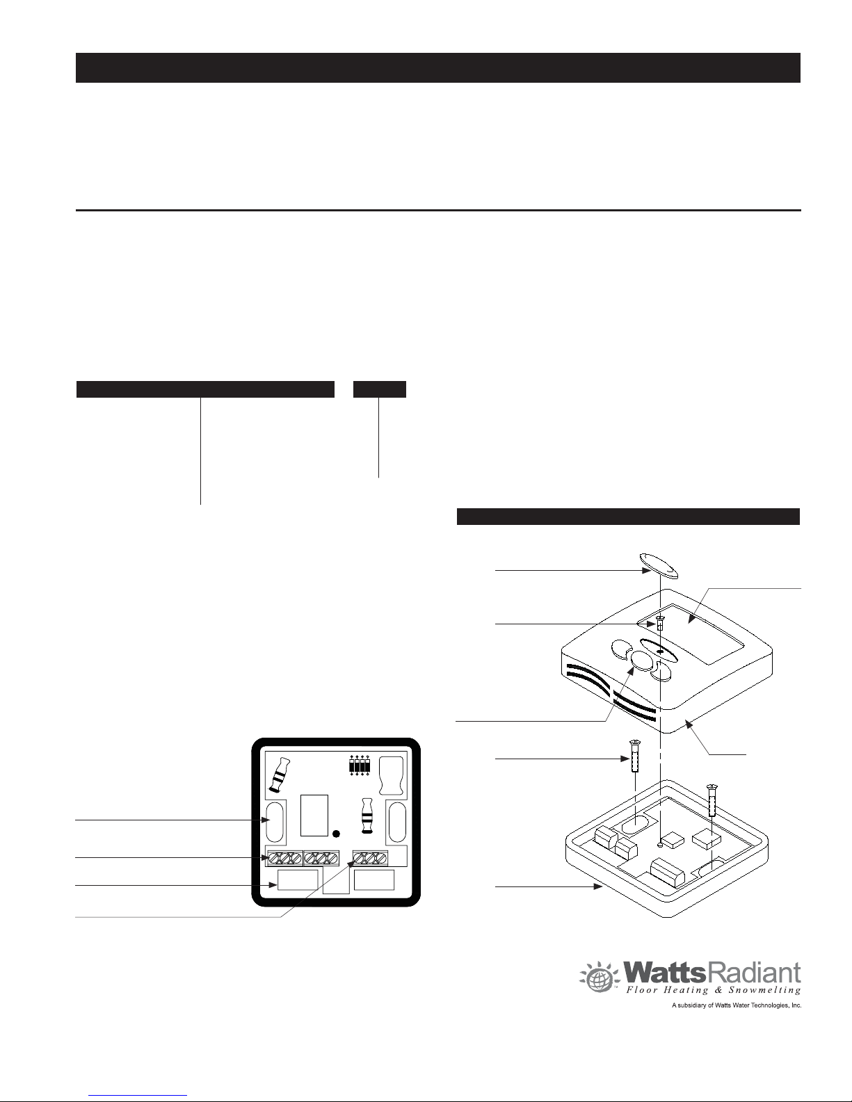
Qty. Description Part # Order #
DualTemp, 24V Digital, Air/Floor P-3285 81009395
Floor Sensor, 10K 500802 81000505
PARAMETER MENU
To enter the parameter menu, press and hold the OK button
for 5 seconds.
Use the +/- keys to select the installation parameter to be adjusted. Press OK to
toggle the parameter setting or to edit its value. When the value begins to blink,
use the +/- keys to adjust its value. Press OK to select the adjusted value.
Toggle to “End” and press OK to exit the installation parameter menu.
INSTALLATION PARAMETERS
J0: °C/°F Temperature display section.
J1: Hot/Cold regulation mode. Select Hot for Heating, Cold for cooling.
Cy: Proportional Integral regulation time cycle, value in minutes
(default: 15 minute cycle).
bp: Proportional Integral regulation band amplitude value in degrees °C/°F
(default: 2.0°C/3.6°F).
J4: NO/NC Normally Open or Normally Close actuator selection.
NC: If using an isolation relay and/or a relay box.
NO: if connecting to a Watts Zone Valve control.
J5: Select PMP (Pump Maintenance Program) to perform a 1 minute
exercise everyday.
J6: Air: Air (room) setpoint. Displays air temperature with floor low (FL) and
high (FH) limits.
Flr: Floor (external sensor) setpoint. Displays floor temperature without floor
low/high limits. Air temperature is not a control boundary.
J7: rEG (proportional Integral) or HYs (0.3°C Hysteresis) regulation type selection.
Cp: Proportional Integral regulation temperature compensation value in °C/°F
(default: 2.0°C/3.6°F).
Ao: Air Sensor offset adjustment (default: no offset), display measure air sensor value.
Fo: Floor sensor offset adjustment (default: no offset), display measure floor
sensor value.
FL: Floor temperature LOW limitation (default: 5°C/41°F), effective only if floor
sensor present and set J6 to Air.
FH: Floor temperature HIGH limitation (default: 28°C/82°F), effective only if floor
sensor present and set J6 to Air.
CLr: Press OK to reset to factory defaults.
End: Press OK to exit installation parameters.
Optional
Floor
Sensor
Optional
Floor
Sensor
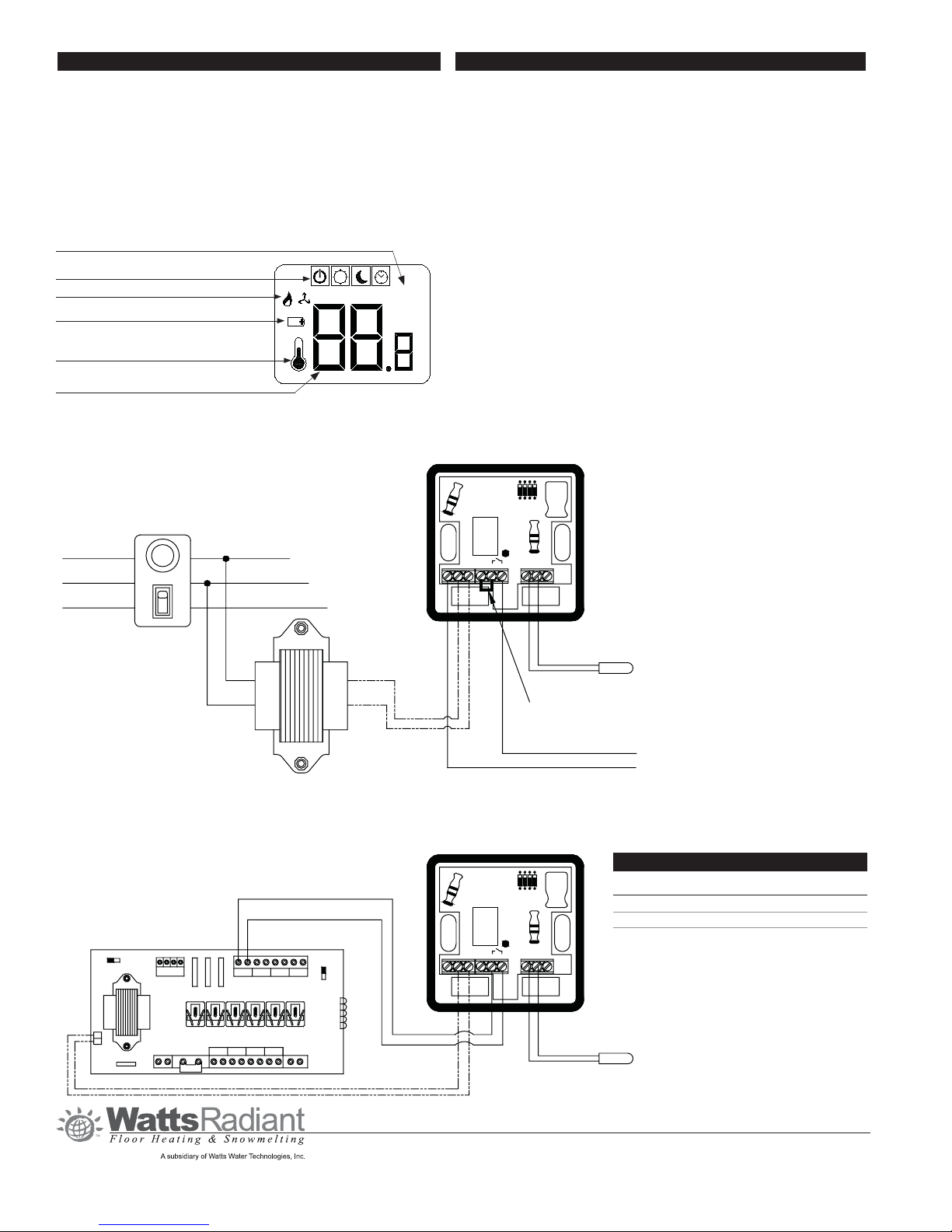
Digital DualTemp with Transformer and Relay
Digital DualTemp with Third Party Relay Box
Transformer
Black
Green
White
Green
White
Black
Fusetron
24Vac Hot
Neutral
To "T1" Terminal
To Relay Coil "A" Side
1 2 3
4
Transformer
24VAC
X
X
ZONE 3ZONE 1ZONE 2 ZONE
4
POWER
INPUT
ZONE 2
ZR
ZC
ZONE 1 ZONE 3 ZONE
4
To "T2" Terminal
To Relay Coil "B" Side
4 4 2 2 6 7 NTC A/B
4 4 2 2 6 7 NTC A/B
R
C
Requires jumper between 2 & 6
Popular Thermostat manuals by other brands

Theben
Theben TimeGuard TRT033 manual

White Rodgers
White Rodgers SuperStat Pro SuperStat Pro Programmable... user guide

APW Wyott
APW Wyott HFW-1S owner's manual

Energate
Energate FZ100C installation guide

Braeburn
Braeburn 5020 user manual

meitav-tec
meitav-tec FMHC220-VFS-FC-MDB01 Owner's manual and technical documentation

Beijer Electronics
Beijer Electronics X2 base 10 v2 HP installation manual

Alpha IP
Alpha IP WTHP 61001 Series manual

ELV Electronik
ELV Electronik ETH comfort100 manual

White Rodgers
White Rodgers 1F80-261 Installation and operation instructions

Rointe
Rointe K series Quick setup guide

Intronics
Intronics DT-04 Plus instruction manual