Warpia Dock n' Charge SWP240A User manual

1
Dock n’ Charge
Product Guide
P/N: SWP240A

2
Contents
1.
Packaging Contents 3
2.
System Requirements 3
3.
Locating the controls 4
4.
Installing the Warpia Dock n’ Charge 5
4.1
Installing the device driver 5
4.2
Uninstalling the device driver 6
4.3
Connecting the Dock n’ Charge to your computer 7
5.
Using the Dock n’ Charge 8
6.
Working with the Dock n’ Charge 10
6.1
Understanding the video output modes 14
6.2
Working with the docking station utility 20
7.
Helpful Tips & Troubleshooting 23
8.
Warpia Support & Contacting Warpia 28

3
1.
Package Contents
Dock n’ Charge USB 3.0 cable
Installation CD
Quick Start Guide DVI to VGA Adapter Power Adapter
2.
System Requirements
Windows Based Laptop or Tablet with an available USB 2.0 or 3.0 Port
Supports Windows XP, Vista, 7 & 8. Does not support Windows RT Tablets
Processor:
1.33 GHz Intel dual-core ATOM Baytrail or higher
2.0 GHz Intel Core2 or higher
2.2 GHz Dual-core AMD Athlon 64 or higher
2GB memory for single monitor, 4GB for dual monitors
Minimum Graphics Interface:
• Win 8: DirectX 10
• Win7/Vista: DirectX 9
• Win XP – Any graphics software
30 MB of free hard disc space or more

4
3.
Locating the Controls
①
⑤
b
⑤
② ⑥
③ ⑧
④ ⑦
⑨
④
b
⑩
①
Power button Used to turn on or turn off the docking station.
②
Power indicator light Lights when the docking station is powered
③
Headset and microphone combo jack Used to connect a microphone, a headset, or a
speaker.
④
Front panel super speed USB 3.0 Used to connect USB devices (USB 1.0, USB 1.1, USB
connector 2.0, and USB 3.0 compatible).
④
b
Front panel super speed USB 3.0 Used to connect USB devices (USB 1.0, USB 1.1, USB
connector with 2.0A charging 2.0, and USB 3.0 compatible) and for high current (2A)
charging for USB components
⑤
Rear panel super speed USB 3.0 Used to connect USB devices (USB 1.0, USB 1.1, USB
connector 2.0, and USB 3.0 compatible).
⑤
b
Rear panel super speed USB 3.0 Used to connect USB devices (USB 1.0, USB 1.1, USB
connector with 2.0A charging 2.0, and USB 3.0 compatible) and for high current (2A)
charging for USB components
⑥
Gigabit Ethernet connector Used to connect a local area network (LAN) cable.
⑦
DVI-I video output connector Connects an external monitor with a DVI cable.
You also can connect a DVI-I to VGA adapter to the
DVI-I video output connector, and connect the
external monitor with a VGA cable to the DVI-I to
VGA adapter.
⑧
HDMI output connector Connects an external monitor or TV with a HDMI cable.
⑨
USB 3.0 upstream connector Main Connection to the laptop, tablet or computer.
⑩
DC-in power jack Used to connect to the power adapter.

5
4.
Installing the Warpia Dock n’ Charge
4.1
Installing the Software Driver
Insert the CD into the computer and laptop CD-ROM
• The disc should start automatically. If the disc does not start automatically, do
one of the following:
• If the autoplay window opens, click Run Warpia.exe
• If the autoplay window does not open, do one of the following:
–For the Windows XP, Windows Vista, or Windows 7 operating system, go into
My Computer or Computer, then double-click the CD/DVD drive icon.
–For the Windows 8 or Windows 8.1 operating system, open File Explorer and
click Computer or This PC, then double-click the CD/DVD drive icon.
• Follow the instructions on the screen to install the device driver.
• Restart your computer after the completion message is displayed. The system will
automatically identify and configure the docking station. The video output
function
of the docking station will be automatically enabled after the configuration is
completed.
Installing driver directly from Warpia.com:
• Go to www.warpia.com/support/drivers
• Click on the Dock n’ Charge (SWP240) Driver Download
• Click on the Download Windows Driver Icon
• Once driver is downloaded, click on driver file to load driver

4.2
Uninstalling the Device Driver
For the Windows XP, Windows Vista, or Windows 7 operating
system:
1.
Exit all applications that use the Dock n’ Charge.
2.
Click Start ➙ Control Panel ➙ Programs and Features ➙ Uninstall
DisplayLink Graphics.
3.
Follow the instructions on the screen to uninstall the device driver.
4.
Restart your computer if necessary.
For the Windows 8 operating system:
1.
Exit all applications that use the Dock n’ Charge.
2.
Go to Control Panel by doing one of the following:
From the desktop, move the pointer to the top-right or bottom-right
corner
of the screen to display the charms, and then click Settings ➙ Control
Panel.
From the Start screen, do the following:
a)
Move the pointer to the top-right or bottom-right corner of the screen
to display the charms.
b)
Click Search
c)
On the Apps screen, scroll to the right side, and click Control Panel in
the Windows System section.
3.
Depending on your Control Panel mode, do one of the following:
a)
Click the Uninstall a program option under the Programs menu
b)
Click Programs and Features.
4.
Select the DisplayLink Graphics software and then right-click your mouse. The
Uninstall option is displayed.
5.
Click Uninstall.
6.
Follow the instructions on the screen to uninstall the device driver.
7.
Restart your computer if necessary. 6

7
4.3
Connecting the Dock n’ Charge to Your Computer
To connect the docking station to your Laptop or Tablet, do the
following:
1.
Connect the dc-in connector of the power adapter to the docking station.
2.
Connect the power plug of the power cord to an electrical outlet. Press the power
button to turn on the docking station.
3.
Connect the USB B plug of the USB 3.0 cable to the USB 3.0 upstream
connector on the docking station.
4.
Connect the USB A plug of the USB 3.0 cable to an available USB connector on
the notebook computer. A USB 3.0 port will have higher performance than a
USB 2.0 port, though both will work under normal circumstances
Notes:
•
Connecting the Dock n’ Charge to any input other than a USB 3.0/2.0 connector or
using any USB cable other than a USB 3.0/2.0 cable might impact performance,
especially video playback and Ethernet performance.

8
5.
Using the Dock n’ Charge
This section provides information on how to use the headset and
microphone jacks, Gigabit Ethernet connector, USB connectors, and
video outputs on the Dock n’Charge.
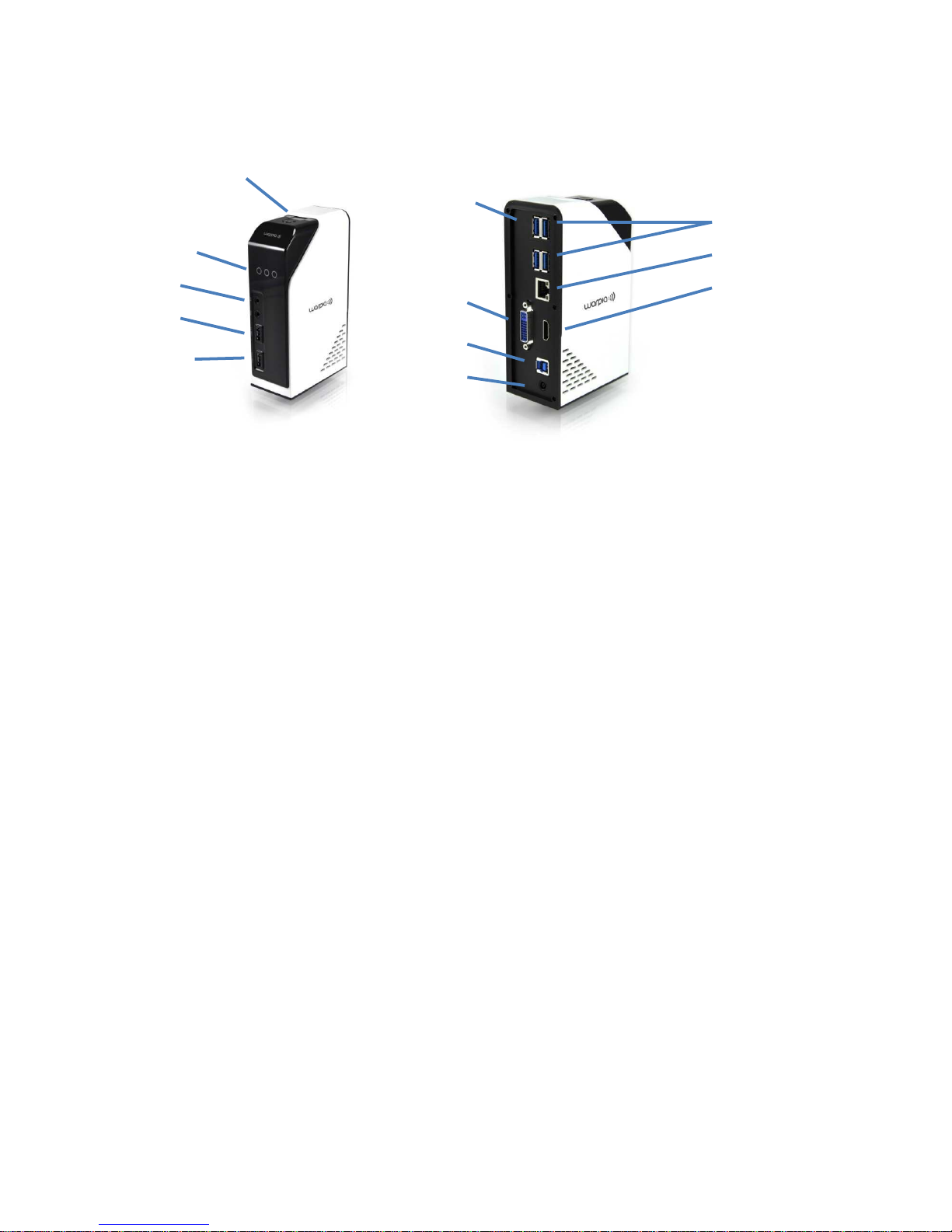
Using the headset and microphone jacks:
The headset and microphone jacks are located in the front of the Dock n’Charge and
are both 3.5 mm in size.
To use the headset and microphone jacks simply, connect your headset, speaker or
microphone to the appropriate jack.
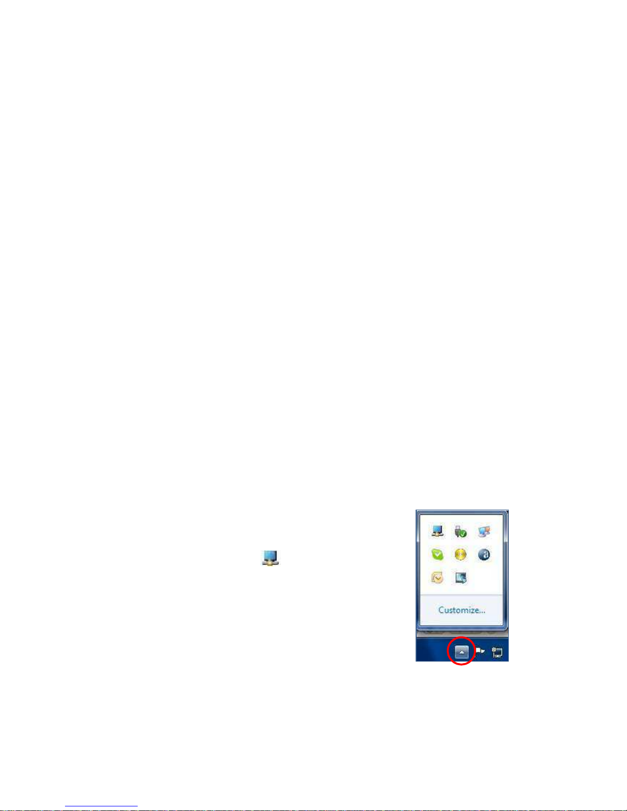
Note: The headset and microphone jacks on the docking station are automatically
enabled when you have successfully connected the docking station to your laptop or
tablet and installed the device driver. However, if you cannot hear anything from the
headset connected to the 3.5mm jack on the docking station, you can manually
enable the headset by right clicking on the volume icon in the taskbar
Using the Gigabit Ethernet connector
To use the Gigabit Ethernet connector on the docking station, connect the docking
station to a standard 10 Mbps, 100 Mbps, or 1000 Mbps network, and wait until the
docking station is fully configured by the Windows operating system.
Using the USB connectors
To use the USB connectors, connect a USB device to any of the six USB connectors on
the docking station with a USB cable. When the USB device is correctly connected to
a USB connector on the docking station , an information window will be displayed in
the Windows notification area, indicating that the USB device has been connected to
the computer.
Using the USB 3.0 connector with battery charging function
The USB 3.0 connector with battery charging function enables you to charge USB
devices even when the computer is in sleep or hibernation mode, or the docking
station is disconnected from the computer. 2 of the USB 3.0 ports enable battery
charging, 1 in the front and 1 in the back. They are clearly marked on the unit.
Notes:
•Most mobile devices can be charged by the USB 3.0 port with battery charging
function, but some devices with special configurations might not be charged.
•The charging time varies depending on the device configuration and the
environment.

9
Using the video outputs
The video outputs on the Dock n’ Charge consist of one HDMI connector and
one DVI-I connector. A VGA monitor can be plugged into the DVI-I output with the
included DVI to VGA adapter. You can simultaneously connect up to two external
displays to the docking station using the two video outputs. You do not have to
disconnect the docking station from your computer each time when you connect the
external displays.
To use the video outputs, connect a DVI cable (or VGA cable using the included
adapter) to an external display. For displays with an HDMI input or for connecting
the docking station to a television, you can use the available HDMI output. This
output supports both video & audio to the television.

10
6.
Configuring External Displays
This Section describes how to use DisplayLink Software which is
included with the Dock n’ Charge and is used to run the external
displays
Notes:
• The DisplayLink System tray Graphical User Interface (GUI), covered below, will only
be available when the Dock n’ Charge is plugged into the USB port of the computer
and an external display is plugged into the Dock n’ Charge
• Terminology for “Mirror Mode” can vary between operation systems and the
DisplayLink GUI. The terms “Clone”, “Mirror”, and “Duplicate” are interchangeable and
provide the same function of making the contents of the selected displays identical.
Resolution Support
When a Display is connected to the Dock n’ Charge, the DisplayLink host software
reads the supported modes (resolutions) of the Display. These are the only modes
offered through the DisplayLink GUI or Windows Display Properties window. The
software will use the monitor’s preferred mode by default.
If the Display does not report any supported modes, DisplayLink will offer a list of
default modes to choose
Note: This communication standard is called EDID. While connecting your external
display directly to your computer may allow you to use other resolutions that what we
provide, we strictly adhere to the EDID protocol. This is the only way to ensure that a
resolution or refresh rate that could cause damage to the external Display is never
used.
Windows 8 & 7 – Controlling the Display
When Displays are attached, an icon appears in the taskbar. This gives you access to
the DisplayLink Manager menu.
To use the DisplayLink Manager menu:
Click on the DisplayLink icon:
If the DisplayLink Icon is not showing, from the Taskbar,
click on the ‘
Show Hidden Icons’
arrow to show all available icons.

After clicking on the DisplayLink icon, a menu appears with several options. They are
shown and described below.
Select an option from the menu, using the following tables for the options available
11

Display
Description
Screen
Resolution
Displaysalist ofavailableresolutions. Someresolutions
may be enclosed by [ ].Please see, Inferred Modes.
This optionis not available inmirror modeasthe resolution
is definedasthe resolutionofthe main monitor.
Screen
Rotation
Normal
No rotationisappliedtothe DisplayLink display
Rotated Left
Rotatestheextendedor mirroreddisplay by270 degrees.
RotatedRight
Rotatesthe extendedor mirroreddisplay by90 degrees.
Upside-Down
Rotatesthe extendedor mirroreddisplayby 180 degrees.
ExtendTo:
Right
Extendsthedisplaytothe right ofthe primary display.
Left
Extendsthe displaytotheleft oftheprimary display.
Above
Extendsthe display aboveofthe primarydisplay.
Below
Extendsthe display below the primary display.
Extend
Extends yourWindows desktop ontothis display.
Set as Main
Setsthis screenas the primary display.
Switchesoffthedisplayofthenotebookandmakesthe
DisplayLink displaythe main display.
Copieswhat is onthe main display and reproduces it onthis
display.
12

13
Display
1\11
enu
Description
Off
Switches offthis display.
Optimize forVideo
(WindowsVista
Only)
Select this option for better movie playback performance on the DisplayLink
enabled displays. Only select this optionwhen playingbackvideo content.
Note:Text may appear less clear when enabled.
Fit to TV
Ifthe Windows desktop does not completely appear on the TV, this option can
be
usedto adjust the size oftheWindows desktop. See "Fit to
TV"
for details on
how to configurethis feature.
Notes:
This optionwillonly appear when 1DisplayLinkUSBscreen is connected
This option will only work in extend mode. Selecting the option in mirror mode
will
extend the displays.

14
6.1
Understanding the Video Output Modes
The Dock n’ Charge works in the following three video output modes:
•“Extend mode”
•“Mirror mode”
•“Single-display mode”
By default, the docking station works in extend mode. All three options can be
changed by clicking on the DisplayLink icon located in the Task Bar and discussed
earlier in section 6.0
Extend Mode
When the Dock n’ Charge is in extend mode, it splits your display across multiple
monitors.
There are three options when you are using Extend Mode:
•Extend: When you select this option, your Laptop/Tablet monitor becomes the
primary display and the external monitor(s) become the secondary display(s), and
the external monitor display(s) are on the right side of the notebook computer
monitor display by default.
•Extend To: When you select this option, your Laptop/Tablet monitor becomes
the primary display and the external monitor(s) become the secondary display(s).
You can give each monitor its own frame buffer through the submenu options
Right, Left, Above, and Below. The display space is a continuous area; therefore,
windows and objects can be moved between different
displays, or even straddled
across multiple displays.
•Set as Main Monitor: When you select this option, the external monitor(s)
become the primary display(s) and the Laptop/Tablet monitor becomes the
secondary display.

15
Mirror mode
When the Dock n’ Charge is in mirror mode, it clones your Laptop/Tablet screen to the
external monitor(s). The docking station automatically selects the settings (screen
resolution, color quality, and refresh rate) for the external monitor(s), which will enable
the best resolution based on your Laptop/Tablet’s resolution capabilities.
Single-display mode
When the Dock n’ Charge is in single-display mode, it enables you to show your
desktop on only one screen.
There are two options when you are using single-display mode:
•Laptop/Tablet Monitor Off:
When you select this option, the display of your
computer monitor turns off
and the display of the external monitor turns on.
Note: This option is available when there is only one external monitor
connected to the docking station.
•Off:
When you select this option, the display of the external monitor(s) turns off and
the
display of your notebook computer monitor turns on. However, the other
functions such as audio, Ethernet, and USB connection still work though the
display is off.

16
Fit to TV
What is Fit to TV?
• If using your Dock n’ Charge to connect to a TV, all of the Windows desktop may
not be available to view. Many TVs will automatically 'overscan' the image streamed
by cutting off the borders and filling the screen with the image.
• On some TVs it may be possible to turn this 'overscan' off in your TVs settings
menu. Consult your TVs User Manual to see if this is an option for you. If you can do
so, then you will not need to use the Fit to TV function of the DisplayLink UI. This is
the best way to correct this issue.
• Fit to TV can be used to reduce the size of the Windows desktop on the TV screen.
Notes:
• Fit to TV only works in extend mode. If choosing the option while in mirror mode,
the DisplayLink screen will change to extend and be placed above the laptop screen in
Windows Display Properties.
• Fit to TV does not support rotated modes.
Using ‘Fit to TV’
•To configure Fit to TV, choose the option from the DisplayLink GUI. The following
interface appears:

17
•You will also see a red border on the External display
•The red border shows the size of the new Windows desktop. Use the “+” and “-”
controls on the Fit to TV GUI to change the size of the red border until it fits on the TV
screen.
Note: Finer configuration of the size of the border can be achieved by holding down
the CTRL key and clicking the “+” and “-”.
•Once the red border is at the edges of the TV screen, click “Apply” to resize the
Windows desktop.

18
Supported resolutions and refresh rates
The following table lists the refresh rates supported at various resolutions for the Dock
n’ Charge’s video outputs.
Supported resolutions and refresh rates:
SN
R
e
s
olu
t
ion
R
e
f
r
e
s
h
r
a
t
e
(
U
ni
t
:
H
z
)
1
64
0
x
480
60
,
67
,
72
,
75
,
85
2
72
0
x
400
70
,
85
,
88
3
72
0
x
480
50
,
60
4
76
8
x
576
50
,
60
5
80
0
x
480
60
6
80
0
x
600
56
,
60
,
72
,
75
,
85
7
83
2
x
624
75
8
84
8
x
480
60
9
102
4
x
600
60
10
102
4
x
768
60
,
70
,
75
,
85
11
115
2
x
864
75
12
115
2
x
870
75
13
128
0
x
720
50
,
60
14
128
0
x
768
60
,
75
,
85
15
128
0
x
800
60
16
128
0
x
960
60
,
85
17
128
0
x
1024
60
,
75
18
136
0
x
768
60
19
136
6
x
768
50
,
60
20
136
8
x
768
60
21
140
0
x
1050
60
,
75
,
85
22
144
0
x
900
60
23
160
0
x
900
60
24
160
0
x
1200
60
25
168
0
x
1050
60
26
192
0
x
1080
50
,
60
27
192
0
x
1200
60
28
204
8
x
1080
60
29
204
8
x
1152
60

19
Inferred Modes
Some modes in the DisplayLink GUI are shown with [ ] around them.
•This occurs when connecting a monitor with a preferred mode higher than the
maximum supported resolution of the W device
•In this case, the preferred resolution of the monitor cannot be supported. However
we add lower resolutions of the same aspect ratio to be tried with the monitor. Modes
in square brackets [ ] imply that these are modes not reported by the monitor, but
have
been made available by the DisplayLink software for you to try.
•As these are inferred modes from the preferred mode of the monitor, they are not
guaranteed to work with the display.

20
6.2
Working with the Docking Station Utility
Checking for updates
The DisplayLink utility is able to check whether there is any update for the device driver
in the Windows 7, Windows8, and Windows 8.1 operating systems.
To check for device driver updates, do the following:
1.
Click the DisplayLink icon in the Windows notification area. A pop-up menu opens.
2.
Select Check for updates. The docking station utility will automatically search for
available device driver updates.
Notes:
•This feature is supported only in the Windows 7, Windows 8, and Windows 8.1
operating systems.
•The DisplayLink icon is displayed only when an external monitor is connected
to the docking station .
•Ensure that your notebook computer is connected to the Internet when you
are using this feature.
Manually enabling the headset and microphone jack’s
To manually enable the headset and microphone jack on the docking station,
depending on the operating system you are using, do one of the following:
For the Windows XP operating system:
1.
Click the DisplayLink icon in the Windows notification area. A pop-up menu
opens.
2.
Select Audio Setup. The Sound and Audio Devices Properties window opens.
3.
Click the Audio tab.
4.
Select a USB audio line-out device from the Sound playback panel, and then select
a USB audio line-in device from the Sound recording panel.
For the Windows Vista, Windows 7, Windows 8, or Windows 8.1 operating system:
1.
Click the DisplayLink icon in the Windows notification area. A pop-up menu
opens.
2.
Select Audio Setup. The Sound window is displayed.
3.
Click the Playback tab to select a USB audio line-out device, and then click the
Recording tab to select a USB audio line-in device.
4.
Click OK.
Table of contents