Wasp 718W User manual

1N718W 7/99
TTAABBLLEEOOFFCCOONNTTEENNTTSS
718W
IINNSSTTAALLLLAATTIIOONNGGUUIIDDEE
Directed Electronics, Inc.
®
What Is Included. . . . . . . . . . . . . . . . . . . . . . . . . . . . . . . . . . . . . . . . 2
Installation Points to Remember . . . . . . . . . . . . . . . . . . . . . . . . . . . 2
Determining Component Locations. . . . . . . . . . . . . . . . . . . . . . . . . 3
Control Module . . . . . . . . . . . . . . . . . . . . . . . . . . . . . . . . . . . . . . 3
Status LED . . . . . . . . . . . . . . . . . . . . . . . . . . . . . . . . . . . . . . . . . 3
Wire Connection Guide . . . . . . . . . . . . . . . . . . . . . . . . . . . . . . . . . . 4
Transmitter/Receiver Learn Routine . . . . . . . . . . . . . . . . . . . . . . . . 4
To Enter the Transmitter/Receiver Learn Routine . . . . . . . . . . . . . 4
Operation Settings Learn Routine . . . . . . . . . . . . . . . . . . . . . . . . . . 4
To Enter the Operation Settings Learn Routine. . . . . . . . . . . . . . . 5
Feature Descriptions . . . . . . . . . . . . . . . . . . . . . . . . . . . . . . . . . . . . 5
Shock Sensor Adjustment . . . . . . . . . . . . . . . . . . . . . . . . . . . . . . . . 5
To Adjust the Warn Away Level . . . . . . . . . . . . . . . . . . . . . . . . . . 6
To Test and Adjust the Current Warn Away Setting. . . . . . . . . . . . 6
To Adjust the Shock Sensor Full Trigger. . . . . . . . . . . . . . . . . . . . 7
To Test and Adjust the Current Full Trigger Setting . . . . . . . . . . . . 7
Troubleshooting. . . . . . . . . . . . . . . . . . . . . . . . . . . . . . . . . . . . . . . . 8

Do not disconnect the battery if the vehicle has an anti-theft-coded radio. If equipped with an air bag, avoid dis-
connecting the battery if possible.
IMPORTANT: Many airbag systems will display a diagnostic code through their warning lights after
they lose power. Disconnecting the battery requires this code to be erased, which can require a
trip to the dealer.
Before beginning the installation:
• Remove the domelight fuse.This prevents accidentally draining the battery.
• Roll down a window to avoid being locked out of the car.
INSTALLATION POINTS TO REMEMBER
2
© 1999 Directed Electronics, Inc. N718W 7/99
Two 491T Remote Transmitters
Control Module
Status LED
WHAT IS INCLUDED

Control Module
Some things to remember about mounting the control module:
• Mount the control module in the engine compartment,
away from heat sources such as radiators, exhaust
manifolds, turbochargers, and heat shields. Also avoid
mounting the control module in areas that must be
accessed for routine vehicle maintenance.Some good
places for mounting the control module are shown in
the diagram at the right.
• Mount it where a thief cannot easily disconnect it,
whether the hood is open or shut. Both the control
module and its wires should be difficult to find. This
usually involves disguising the wire to look like a fac-
tory harness.
• Mount the unit with the siren facing down.This will prevent water damage to the unit.
• Route the wires away from the unit and make sure they are securely fastened away from the moving parts
of the engine.
• Place the antenna as high as possible and as straight as possible for maximum operating range.
Status LED
Things to remember when positioning the Status LED:
• It should be visible from both sides and the rear of the vehi-
cle, if possible.
• It needs at least 1/2" clearance to the rear.
• It is easiest to use a small removable panel, such as a switch
blank or a dash bezel. Remove it before drilling your 9/32" hole.
• Use quick-disconnects near the LED wires if the panel is re-
movable. This lets mechanics or other installers remove the
panel without cutting the wires.
DETERMINING COMPONENT LOCATIONS
3
© 1999 Directed Electronics, Inc. N718W 7/99

BLUE/WHITE 2V (-) LED output: Connect this wire to the blue wire of the supplied LED. Connect the RED wire of
the LED to a fused source of (+)12V.
BLACK (-) chassis ground input: Connect this wire to bare metal, preferably with a factory bolt rather than your
own screw (screws tend to either strip or loosen with time).
RED (+)12V constant power input: Before connecting this wire, remove the supplied fuse. Connect to the battery’s
positive terminal or to the (+)12V feed to the dome light circuit.
NOTE: Always use a fuse within 12 inches of the point you obtain (+)12V.Do not use the 10A fuse
in the harness for this purpose.This fuse protects the module itself.
This system uses a microprocessor-based Learn Routine™to learn and store transmitters in memory. Up to four
transmitters are retained in memory, even if the security system is disconnected from the vehicle battery.
To enter the Transmitter/Receiver Learn Routine:
1. Power the system up. If the system is already powered up, it must be powered down
before it will enter the Transmitter/Receiver Learn Routine™.
2. Within 5 seconds press on the first transmitter. The siren will chirp once.
3. Within 5 seconds press on the first transmitter AGAIN.The siren will chirp twice.
4. Within 5 seconds press on the first transmitter a THIRD time.The unit will gener-
ate one long chirp.
5. Repeat Steps 2 through 4 for all transmitters that need to be learned.The system can
learn up to four transmitters.
The Transmitter Learn Routine™will automatically be exited if 5 seconds elapse without the unit receiving a trans-
mitter code.The system will generate one short chirp followed by a long chirp when the Learn Routine™is exited.
TRANSMITTER/RECEIVER LEARN ROUTINE™
WIRE CONNECTION GUIDE
4
© 1999 Directed Electronics, Inc. N718W 7/99

Many of the system features are programmable.The Operation Settings Learn Routine™is used to access and pro-
gram the system features.You must program the transmitter before programming the system features.
To enter the Operation Settings Learn Routine:
1. Arm the system by pressing .
2. Disarm the system by pressing again.
3. Press and hold both buttons on the transmitter until the unit generates a long chirp.
The long chirp is followed by a short chirp indicating that you have accessed Feature
Number 1 in the Operation Settings Learn Routine™.
4. Release the transmitter buttons.
Repeat steps 3 and 4 to advance to the next feature. Each time you advance a feature, the short siren chirps will
indicate which feature number you have accessed.
5. Program the selected feature. Pressing Button I on the transmitter will select the one-
chirp setting and the siren will chirp once. Pressing Button II on the transmitter will
select the two-chirp setting and the siren will chirp twice.The default settings are the
one-chirp settings except where indicated by bold text.
After programming a feature, another feature can be selected by repeating steps 3 and 4.The Learn Routine™will
be exited if 5 seconds elapse between steps.The system will exit Learn Routine™immediately after the last fea-
ture has been selected.When the Operation Settings Learn Routine™is exited, the unit will chirp once followed by
a long chirp.
or
Feature One-Chirp Two-Chirp
Number Feature Setting Setting
1 Current Sense On Off
2 Current Sense Delay 5 seconds 5 minutes
3 Audible Arm/Disarm Confirmation On Off
4 Code Hopping™On Off
OPERATION SETTINGS LEARN ROUTINE™
5
© 1999 Directed Electronics, Inc. N718W 7/99

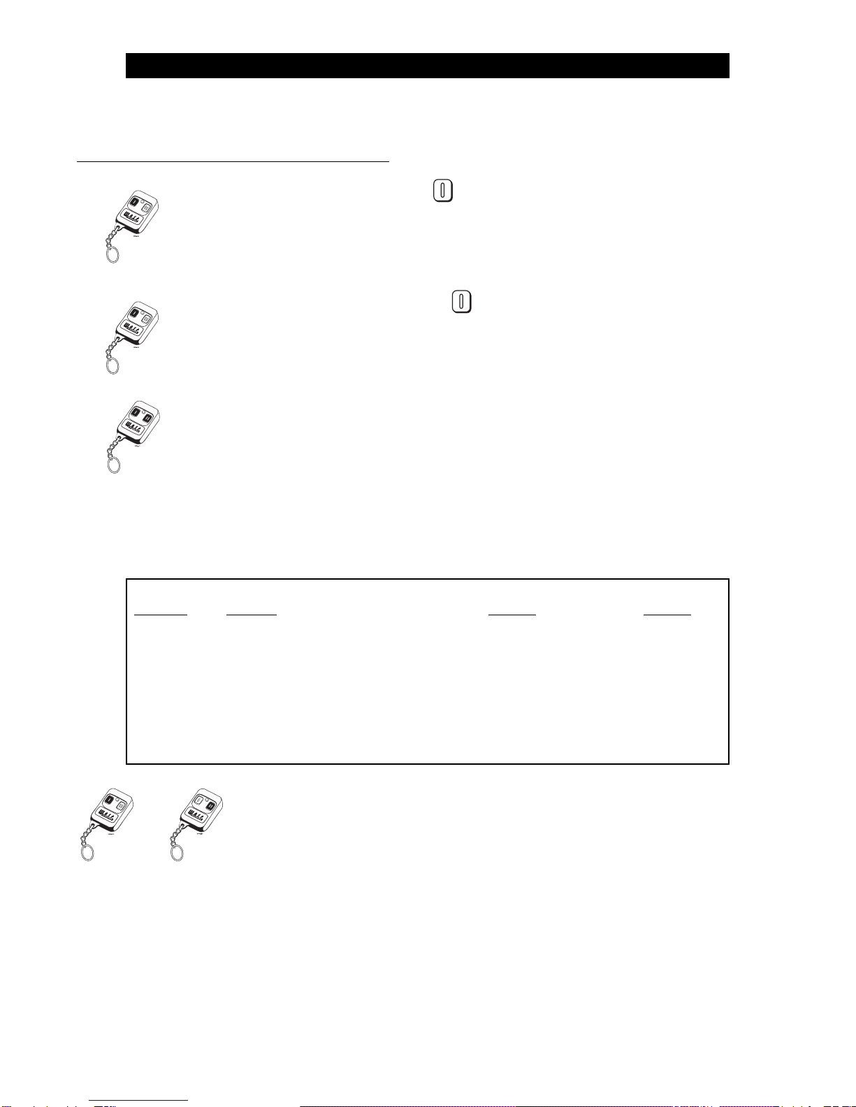
1 CURRENT SENSE ON/OFF: This feature is used to defeat the current sensor of the unit. If turned off, the sys-
tem cannot detect when the vehicle doors open.
2 CURRENT SENSE DELAY 5 SECONDS/5 MINUTES: This feature selects the delay time before current sen-
sor can trigger the unit. In some vehicles, electric fans and other circuits may stay on after the ignition is turned off.
Selecting the 5 minute delay may prevent those systems from triggering the current sensor.
3 ARM/DISARM CHIRPS ON/OFF: This feature controls the chirps that confirm the arming and disarming of the
security system.
4 CODE HOPPING™ON/OFF: The system uses a mathematical formula to change its code each time the trans-
mitter and receiver communicate.This makes the group of bits or "word" from the transmitter very long.The longer
the word is, the easier it is to block its transmission to the unit.Disabling the Code Hopping™feature lets the receiv-
er ignore the Code Hopping™part of the transmitter word. As a result, the unit may have better range with Code
Hopping™off.
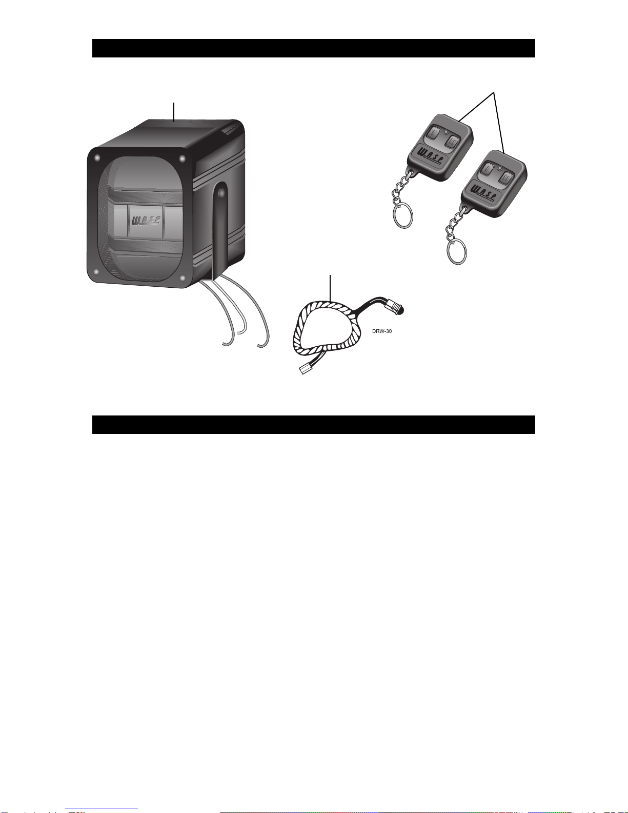
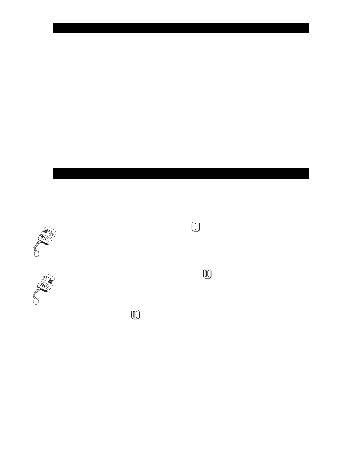
The system features a Doubleguard shock sensor inside the control unit. All adjustments to the sensor are made
using the transmitter.
To adjust the Warn Away level:
1. Disarm the system by pressing .
2. Within five seconds press and hold on the transmitter until the unit generates a
long chirp.
3. Release on the transmitter.
To test and adjust the current Warn Away setting:
Strike the vehicle to test the current setting. If the impact is detected the unit will chirp three or four times. If the
current setting is acceptable, do nothing and the unit will exit shock sensor adjustment mode. If the current setting
is unacceptable, press Button I to decrease the sensitivity or Button II to increase the sensitivity. Each time Button
I is pressed the unit will emit one chirp and the sensitivity is decreased one step. Each time Button II is pressed
the unit will emit two chirps and the sensitivity will be increased one step.There are 16 possible settings.When the
maximum or minimum setting is achieved the siren will emit a long chirp.
SHOCK SENSOR ADJUSTMENT
FEATURE DESCRIPTIONS
6
© 1999 Directed Electronics, Inc. N718W 7/99

To adjust the shock sensor full trigger:
1. Arm the system by pressing .
2. Within five seconds press and hold on the transmitter until the unit generates a
long chirp.
3. Release on the transmitter.
To test and adjust the current full trigger setting:
Strike the vehicle to test the current setting. If the impact is detected the unit will chirp three or four times. If the
current setting is acceptable do nothing and the unit will exit shock sensor adjustment mode. If the current setting
is unacceptable press Button I to decrease the sensitivity or Button II to increase the sensitivity. Each time Button
I is pressed the unit will emit one chirp and the sensitivity is decreased one step. Each time Button II is pressed
the unit will emit two chirps and the sensitivity will be increased one step.There are 16 possible settings.When the
maximum or minimum setting is achieved the siren will emit a long chirp.
NOTE: If more than five seconds elapse without an adjustment, shock sensor adjustment mode is
exited. Repeat steps 1 through 3 to make additional adjustments.
The siren will generate one long chirp followed by two short chirps when the shock sensor adjustment mode is
exited.
7
© 1999 Directed Electronics, Inc. N718W 7/99

The current sensor does not work.
Is it programmed off? Is it programmed for 5 minute delay? See
Shock Sensor Adjustment
section.
The current sensor can sense the domelight circuit more effectively if the RED (+) 12V input wire is con-
nected directly to the dome light positive circuit. This is not necessary in most cases, but will help when
the dome light circuit is extremely low current.
The shock sensor is not sensitive enough.
The mounting of the control unit is critical to shock sensor performance. If relocation of the control unit
does not improve performance of the sensor, the angle of the unit and the bracket may be changed as
shown below. Remember, the siren must be protected against water damage and the more the angle is
changed, the easier it is for water to collect in the siren housing.
After programming, the remote does not arm or disarm the system.
Follow the instructions for Transmitter/Receiver Learn Routine™carefully. See
Transmitter/Receiver Learn
Routine
section.The remote button must be pressed three separate times in order for the system to learn
the transmitter code properly.
DRW-11
TROUBLESHOOTING
8
© 1999 Directed Electronics, Inc. N718W 7/99
Table of contents
Popular Car Alarm manuals by other brands

Fortress Automotive Security
Fortress Automotive Security FS-52 Installation handbook

Authorized Alarms
Authorized Alarms Controur operating manual

Directed Electronics
Directed Electronics Concept 650 owner's guide

Sowa
Sowa ATS 02 operating instructions

Directed Electronics
Directed Electronics 700 ESP owner's guide

Cobra
Cobra 4600 CAN/PLIP user manual

Directed Electronics
Directed Electronics 446 Series installation guide

Clifford
Clifford 20 owner's manual

AUTHOR Alarm
AUTHOR Alarm Kvant 120 operating manual

Audiovox
Audiovox Prestige Platinum APS-255 owner's manual

Clifford
Clifford intelliguard 800 owner's manual

Volvo
Volvo 2045 installation instructions