-1-
PARALYSER 485
USER INSTRUCTIONS
Proudly designed and engineered in Australia by Dynamco Pty
Ltd.
The Cyclops Paralyser 485 has been tested to and meets
Australian Standards AS/NZS 3749.
Congratulations on having one of the world’s most advanced
and unique Australian designed and engineered vehicle security
systems, installed in your vehicle!
ARMING AND DISARMING
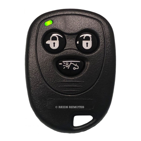
To arm the P485, press the lock button on the remote control
supplied by the vehicle manufacturer. Arming the system is
accompanied by two ashes from the indicators and two chirps
from the siren. The status LED (red light on the dash) will glow,
then begin ashing after 5 seconds.
To disarm the P485, press the unlock button on the remote
control. Disarming the P485 is accompanied by one ash from
the indicators and one chirp from the siren. The siren and
indicator conrmation order can be reversed and/or disabled (see
option settings). The status LED will also extinguish.
AUTO RE-ARMING
The P485 will auto re-arm only in vehicles that feature an auto
re-lock function as part of the original system. Some vehicles re-
lock doors if the vehicle is not entered within a given time after
unlocking by remote control.
INTRUSION DETECTION
The P485 is equipped with four zones of protection doors, boot,
bonnet & glass breakage. The combined zones can be triggered a
maximum of three times after arming. When a zone is triggered,
the siren and indicators will sound and ash for 30 seconds. Both
indicators and siren will reset for ve seconds after each 30-
second trigger period before sounding due to subsequent triggers.
ENGINE IMMOBILISATION
Engine immobilisation is usually provided by the vehicle’s
original equipment system. The P485 does provide another two
independent circuits of immobilisation, however they are only
connected at special request (extra cost).
GLASS BREAKAGE PROTECTION
The P485 is equipped with a sophisticated glass breakage
detection unit. The system will only respond to the breaking of
glass in the vehicle (sound can be mufed by heavy window
tinting). To test the unit simply wind up all the windows and
arm the P485. Wait 30 seconds before tapping the driver’s
side window with a metal object such as a coin. The siren and
indicators will sound and ash. Dull thumping of the windows
should note produce a trigger. Be careful not to smash any
windows.
PROGRAMMABLE OPTIONS
The P485 has a number of options that can be set or reset by
means of the ignition switch. To change these options you need
to do the following:
Open the bonnet and driver’s door, these must remain open
during the entire procedure.
1.
Turn the ignition switch from ACC position to the ON
position the required number of times (see table on next
page). Leave the switch in the ON position when the
required number is reached.
The vehicle indicators will ash approximately two seconds after
last turn. Three ashes shows that the option is set and one ash
shows it has been reset.
Turns Description 1 Flash 3 Flashes
5 Siren chirp order Reversed Standard
7 Immobilisation
dropout time*
When armed After 30
seconds
9Arm/disarm ash
conrmation**
Enabled Disabled
11 Siren/horn output type Pulsed for 30
sec
Constant for
30 sec
13 Arm/disarm
conrmation
Disabled Enabled
15 Voltage drop sensing* Disabled Enabled
17 Door sensing delay 5 seconds 30 seconds
19 Change PIN Code - refer to “Changing PIN”
*Changing these options may drain vehicle battery or reduce alarm effectiveness
- installer option only.
**Disabling option #9 means diagnostics is only visible through status LED.
OVERRIDE
The P485 is overridden in two parts; a high security lock/switch
mounted on the back of the siren and by a four digit PIN entered
through the ignition switch.
SIREN SECURITY SWITCH
Locate the siren under the
bonnet.
Remove the protective black
plastic dust cap and insert
the key into the lock. Turn
90 degrees to over-ride the
P485.
This will instantly stop the siren sounding. The P485 is still
armed. The next step shows how to disarm the P485.
ENTER PIN CODE
If the P485 is triggered, allow siren to reset automatically (after
30 seconds) by sitting inside car with doors shut. If the siren is
switched off, wait for indicators to stop ashing.
Turn the ignition switch to the “ON” position; the status
LED will glow constantly.
Turn ignition switch back to the “ACC” position; the status
LED will begin to ash slowly.
Switch ignition switch to the “ON” position when the
number of ashes match the 1st digit of the PIN.
Repeat previous two steps for the remainder of the PIN.
NB: over-riding the P485 in no way over-rides the vehicle’s
on-board immobiliser. The factory tted immobiliser system is
totally separate, refer to manufacturers over-ride instructions.
*** Any digit marked “0” indicates ten ashes.
CHANGING PIN
The emergency over-ride pin can be changed at any time while
the P485 is disarmed. To enter a new “pin”, carry out the
following procedure: -
Disarm system by pressing the unlock button on the remote
control or using the existing PIN. Ensure the bonnet and
2.
1.
2.
1.
2.
3.
4.
1.
