Wasserlab Micromatic User manual

Micromatic DA
Equipment
User´s Manual
Rev. 7
20.03.17

0. Introduction
This User Manual provides information about the installation, start-up and routine maintenance tasks of the Micromatic equipment.
Before start-up, carefully read the instructions regarding the safety of the device, as well as its electrical and hydraulic connection
aspects.
The User Manual also contains additional information about the equipment and settings, allowing a better understanding of the
operation and care required.
If in doubt, please contact your local distributor or the Wasserlab technical assistance service.
Manufacturer:
Navarra de Tratamiento del Agua S.L.
Pol. Comarca II, C/A-Nº 26
31191 – Barbatain,Navarra, Spain
CIF: ESB31637580

1. Index
0. Introduction................................................................................................................................................................................... 2
1. Index.............................................................................................................................................................................................3
2. Safety Information.........................................................................................................................................................................4
3. Equipment use and specifications.................................................................................................................................................5
3.1 Electrical Power Requirements:......................................................................................................................................5
3.2 Equipment location.........................................................................................................................................................6
3.3 Equipment features: .......................................................................................................................................................6
Equipment dimensions:.....................................................................................................................................................................6
4. Equipment description ..................................................................................................................................................................7
4.1 Equipment exterior: ........................................................................................................................................................7
4.2 Right side.......................................................................................................................................................................7
4.3 Left side..........................................................................................................................................................................7
4.4 Other elements...............................................................................................................................................................7
4.5 Screen and keyboard .....................................................................................................................................................8
4.6 Type II Water Tank.........................................................................................................................................................8
5 Water purification process description............................................................................................................................................9
5.1 Pretreatment ..................................................................................................................................................................9
5.2 Reverse osmosis............................................................................................................................................................9
5.3 Deionisation ...................................................................................................................................................................9
5.4 Type II Water Storage ....................................................................................................................................................9
5.5 Automatic operation of the equipment ............................................................................................................................9
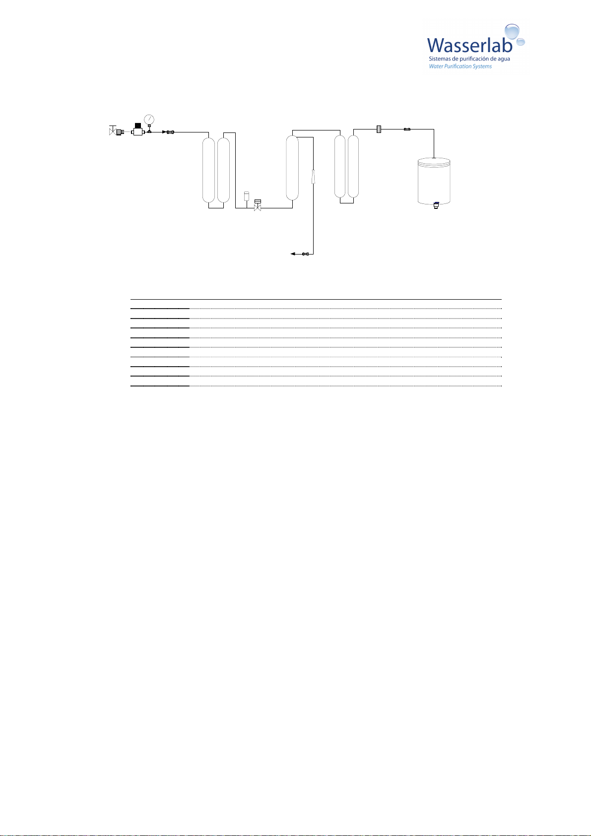
6. Hydraulic diagram.......................................................................................................................................................................10
7. Installation of the equipment.......................................................................................................................................................10
7.1 Unpacking the equipment............................................................................................................................................. 10
7.2 Hydraulic connections ..................................................................................................................................................12
7.3 Equipment start-up....................................................................................................................................................... 13
8. MONITORING ............................................................................................................................................................................ 14
8.1 Symbols and meaning:................................................................................................................................................. 14
8.2 User warnings ..............................................................................................................................................................15
8.3 Entering parameters (set-up menu)............................................................................................................................. 15
9. Maintenance...............................................................................................................................................................................17
9.1 Pretreatment replacement............................................................................................................................................ 17
9.2 Resin cartridge replacement.........................................................................................................................................17
9.3 RO membrane replacement ......................................................................................................................................... 17
10. Calibration ................................................................................................................................................................................18
11. Troubleshooting Guide............................................................................................................................................................. 19
12. EC-Declaration of Conformity....................................................................................................................................................20

2. Safety Information
The security information included in this chapter should be read carefully.
The user should check for compliance with security conditions set out in this Manual to ensure the safe use of the equipment.
In case of doubt, contact the Technical Assistance Service.
Safety information is related to both user protection and equipment protection.
Access to the equipment interior
Only authorised technical service may access the equipment interior to carry out maintenance and repair tasks other than the
routine replacement of expendable items.
Electrical connections
- Check that connection to the power system is 110 - 230 VAC, 50 -60 Hz.
- Only use the transformer supplied with the equipment. Plug Type C, Europlug.
- Supply voltage fluctuations should not exceed 10% of the rated voltage.
- Supported transitional overvoltage: The typical present in the power supply network (category II of the standard IEC
60634-4-443).
- The electrical plug should not be situated below the equipment.
- The electrical plug should be accessible in case of be necessary to disconnect the equipment quickly.
Explosive atmospheres
The equipment is not designed to work in explosive atmospheres.
Environmental pollution permitted
Pollution grade 1 (No environmental pollution or only dry pollution, not conductive).
Feed water and hydraulic connections
The feed water must comply with the specifications listed in this Manual.
Feeding poor quality water (turbidity and/or high hardness, inadequate conductivity, unwanted pollutants, etc.) can result in
deterioration of the equipment components or a lower performance.
Respect the pressure conditions established for the feed water to the equipment. High pressure can damage the hydraulic system.
In these cases, it is necessary to install a pressure regulator before the equipment.
A feed water pressure lower than the minimum required will cause poorer performance and improper functioning of some of the
system components.
Have a stopcock that is easily accessible when you need to cut the water supply to the equipment.
Locate the equipment so that the electric and hydraulic connections located on the rear of the equipment are not
adversely affected.
Prevent straining the power cable or hydraulic connections.
Consumables
Replace the consumables items in the times anticipated and based on the messages from your equipment.
Use only original expendable items. Using non original components may cause equipment damage and loss of guarantee.
To move the equipment, handle it by holding at the base.

3. Equipment use and specifications
Micromatic water purification equipment provides Type II purified water (ASMT) from the tap water.
The equipment combines several processes to supply purified water (pre-filtration, reverse osmosis and deionisation).
The water provided by the equipment is suitable for numerous laboratory techniques, preparation of culture media and other
applications requiring Type II purified water.
Once the equipment has been connected and started up, operation is automatic.
The purified water of the Micromatic equipment is not fit for human consumption.
3.1 Electrical Power Requirements:
110 - 230V AC / 50 - 60 Hz Single-phase / 36W.
Use only the transformer supplied with the equipment.
The power point should not be situated below the equipment.
Power consumption 24 VA
System voltage 24 Vdc
Feed water requirements:
Drinking water (according to European or USA standards)
Maximum Inlet
pressure 6 bar.
Minimun. Inlet
pressure 3 bar
Temperature: 5ºC – 35ºC
Maximum hardness: 300 ppm
(CaCO
3
)
SDI (Silt Density
Index) < 5
Conductivity < 800 µS/cm
Free Chlorine: <1 ppm
Turbidity: < 1 NTU
Deviation from the feed value requirements may cause deterioration of the equipment components and/or a decrease in
performance.
Ambient temperature
Operation: 5ºC – 35ºC
Storage: 5ºC – 35ºC
The ambient temperature and, above all, the feed water temperature affect the equipment's performance.
The ideal operating temperature is in the range between 20 - 25°C.
If the equipment may be submitted to low temperatures, make sure it is no less than 5°C.
Relative humidity HR = No condensation. HR < 80% for Temp. up to 31°C (linear decrease up to 50% at 40°C).

3.2 Equipment location
The equipment is designed for indoor use and < 3000 m altitude.
The location of the equipment must not obstruct the access to the electric connection.
Make sure that the rear connections of the equipment are not adversely affected by an inappropriate location.
An easily accessible stopcock must be installed between the tapping point and the equipment inlet in case the water supply
must be cut.
The equipment needs a drainage to collect the rejection water.
3.3 Equipment features:
Production flow *: 2.5 l/h *
Operating pressure: 2.5 - 6 bar
Conductivity
(compensated at 25°C) < 0.2 µS/cm
Silica removal: >99.9 %
Reverse osmosis performance:
90 - 98%
Weight in operation 12 Kg
* 15% fluctuation. The production values are based on standard operating conditions [25 °C / pH 5 - 7 / 4 bar/250 ppm NaCl] and
may vary depending on the feed water quality and typical variations in the reverse osmosis membranes.
Equipment dimensions:
(*) Reservoir is optional

4. Equipment description
4.1 Equipment exterior:
Electrical connection:
Transformer:
Input: 110 - 230 VAC. Connect to electrical system. Socket Type C, Europlug
Output: 24 VDC, Plug-in type with connection to the back of the equipment
Hydraulic connections:
[0] Tank level:
Connection with open tank level
detector
[1] Rejection:
Rejection water outlet from the reverse
osmosis phase (directed to a drainage)
[2] Tank:
Water outlet from the equipment to a
Type II water storage tank
[3] Feed water:
Equipment feed water inlet.
4.2 Right side
Pretreatment cartridges [1] and [2].
Deionisation resin cartridge (3 and 4)
4.3 Left side
- Reverse Osmosis Membrane (ROM)
- Other components
4.4 Other elements
- Tank
- Transformer
- Spanner wrench for cartridges and ROM

4.5 Screen and keyboard
4.5.1 Screen
Screen with icons indicating operating status of the equipment,
warnings for the user and measurement and control values.
The meanings of the symbols are explained in point 8.1
“Symbols and meaning”.
4.5.2 Keyboard
MODE/ESC
Cancelling commands/ Access to set-up menu
ENTER
Accepting commands
Scrolling the menu
Value decrease
Scrolling the menu
Value increase
4.5.3 Acoustic advice
The equipment beeps when activating any warning. Pressing any
key turns off the sound.
4.6 Type II Water Tank
The equipment produces Type II water that is collected in a
storage tank
that can be supplied with the equipment (optional).
When the equipment is supplied with a Tank, the level is placed
on the tanks.
If not, it is supplied a level detector to be incorporated into the
tank for automatic operation of the system.

5 Water purification process description
Purification phase Remarks
5.1 Pretreatment
Removes:
- Particles of size equal to or above 5 µ.
- 99.99% of hypochlorite.
- Most of the organic material present in the feed water.
On equipment installed in areas where the feed water has high
amounts of suspended solids, turbidity or colloids, it may be
necessary to include additional prefilters to reduce significantly the
presence of substances that may affect the equipment's
performance.
In very hard water it is necessary to install a water softener before
feeding the equipment.
Cartridge 1 and 2
5.2 Reverse osmosis
Removes:
> 99.95 % of organic matter (greater than 150 Dalton) present in
the water and 95 - 98% of the Total Dissolved Solids (TDS).
The RO membrane must operate at pressure of 4 - 6 bar
for optimum performance. There should be a minimum
inlet pressure of 2.5 bar.
In facilities with high inlet pressure (> 6 bar) it is necessary
to install a pressure regulator before the water inlet to the
equipment.
5.3 Deionisation
The permeate passes through a mixed bed of strong cation/anion
resins, retaining all the anions and cations still present in the water
and which have not been removed in the RO process.
The result is a Type II Analytic Grade Water with a conductivity of
less than 0.2 µS/cm (Resistivity > 5 MΩ.cm) newly produced.
Cartridge 3 and 4
-
5.4 Type II Water Storage
Type II Water is stored in an open tank, ready for use.
A level detector must be connected to the tank to work in automatic
mode.
Rear connections:
- [0] Tank level
- [1] Rejection
- [2] Tank
- [3] Feed water
5.5 Automatic operation of the equipment
The equipment has the following operating modes:
- Production: The equipment produces Type II Water that is sent to the storage tank. When the tank is full,
the equipment stops automatically.
- Standby: The equipment does not produce water because the tank is full.
-
Water dispensation: The user obtains Type II Water taking it directly from the storage tank

6. Hydraulic diagram
Feed
water MR MP [P3]
12
PT PB EV1
ROM FR
Rejection [P1]
34
RS
SC3
[P2]
Tank
Type II Water
7. Installation of the equipment
7.1 Unpacking the equipment
- Check that the packaging does not present any kind of damage.
- Carefully unpack the equipment and components. Note if any component is damaged.
- Check that no element of the system is missing:
Micromatic equipment.
Transformer
Spanner wrench
Pipe cutter
1 set of pretreatment cartridges [1] and [2].
1 set of deionization resin cartridges [3] [4]
Tank with level (optional) or Level
User Manual
Water inlet and drainage connection kit.
The equipment is self-supporting. To handle the equipment pick it up from the sides of the base. Note the following
guidelines to locate and connect your equipment:
MR Pressure regulator
MP Pressure gauge
PT Pretreatment 1: Sediment filter, 2: GAC Filter
PB Low Pressure Switch
EV1 Solenoid Valve
ROM Reverse Osmosis Membrane
FR Flow restrictor
TANK Reservoir
RS DI Resin
SC3 Type II conductivity sensor

Equipment location Flat surface
Avoid direct sunlight
Avoid harsh environments (chemical agents, dust, dirt)
Tank location Locate the chosen tank considering the dispensation point of Type II Water. It is preferable that
the tank should be opaque, with cover, and receive no direct sunlight. It is advisable to have a
safety spillway to a drainage outlet.
Electrical connection Transformer:
Power connection : 110 - 230 VAC. Socket Type C, Europlug.
Connection to the equipment: Rear connection Plug-in type
Accessible plug in case of need to disconnect the power supply.
Plug above or beside the equipment.
Hydraulic c
onnection
If a reservoir is not supplied together with the equipment, it is supplied a level to be placed on a reservoir selected by the
user.
It is necessary to make a holes (∅16 mm) to place the fittings for the level and the Type II Water tube.
The level should be placed in vertical position.

7.2 Hydraulic connections
Flexible tube and tube cutter are supplied with the equipment to carry out hydraulic connections.
Quick connections:
The hydraulic connections are made by means of a System known as Quick Connection (QC): Simply insert the
tube until it stops, and it is connected.
To disconnect the tube, first press the central washer of the QC device inwards while pulling the tube in the
opposite direction.
Important: Tubes connected with Quick Connection must have a clean cut, perpendicular to the length of the
tube. The tube section inserted in the connection will be smooth, with no abrasions. Any bevel cut-out or a
damaged tube termination will make the connection imperfect and lead to water leakage.
a. Water inlet: The water inlet will be provided with a stopcock with BSP male threads of 1/2". Thread the connection piece
supplied.
Do not use Teflon for this connection (the connection is fitted with a rubber seal).
If due to highly polluted inlet water it is necessary to install and additional pretreatment, the connection
sequence will be:
Feed water - Enters additional pretreatment - Exits pretreatment - Enters the equipment. All connections are
quick type.
b. Drainage: The drainage point will be at a maximum 3 m far. The Rejection tube must be positioned to
ensure that it cannot move from its position by a flange or by inserting it approximately 30 cm into the drain pipe.
The Rejection tube is connected with a quick connection "Rejection" located at the rear of the equipment.
Using the drain flange:
Drill a 6.5 mm hole in the drain pipe where the Rejection tube is to be inserted.
Place the pad over the hole and the drain flange on top, gripping the pipe. Secure it by tightening the screws on both sides.
Insert the Rejection tube 5 cm, through the flange.
Secure the Rejection tube with the drain flange nut.
c. Tank level: The tank level is connected at the rear fitting "0"

Connect the Micromatic with the Level connector using a wire supplied with the equipment.
d. Water Type II: Connect a tube at the rear fitting 2 with the fitting placed on the cap of the tank.
7.3 Equipment start-up
Once the hydraulic connections have been made, open the stopcock and check for leaks at the connections made, including the
dispensing faucet.
Electrical connection:
First connect the transformer plug-in to the equipment.
Then
connect the transformer to the power system: The equipment will start automatically.
Leave the equipment running until the tank is full.
The screen displays the conductivity value of the water produced.
When the tank is full, the equipment stops the production of water and displays the full tank icon.
The screen displays the conductivity value of the water produced at the time the equipment stopped.

8. MONITORING
The equipment screen displays the operating status and the corresponding values by means of icons.
E
quipment
status
Screen
Standby The screen displays the conductivity value of the water produced.
Full tank icon
Production Displays the conductivity value of the water being produced and sent to the tank.
The icons: Equipment in Operation, Electrovalve, Tank full, are activated.
8.1 Symbols and meaning:
Pre-treatment change
Equipment in operation
Deionisation Resin change
Tank full
Water cut off
inlet electrovalve open
Conductivity probe not working
Notify the technical service
OT
OT equipment setup: Equipment with
open tank
Adjustment Menu
Numeric value of the measurement
Temperature settings
Calibration Menu
RESET
Set the hour meter to 0
Hour meter
µS/cm
Conductivity measurement

8.2 User warnings
The Micromatic equipment carries out constant monitoring of various operating parameters and alerts the user via acoustic signals
and activation of the corresponding icon:
•
Pretreatment changes: When the equipment exceeds the number of operating hours assigned to the pretreatment this warning
is activated, indicating that the cartridges must be changed [1] and [2].
•
Deionisation resin change: This warning is activated when the equipment detects that the Type II Water conductivity is higher
than the set value. By default, a maximum of 10 µS/cm is set. The user can select a different value (between 1 and 20 µS/cm).
•
Water cut off: An icon is activated indicating that water has stopped entering the equipment.
•
Conductivity probe: Notify the technical service Conductivity probe does not measure correctly.
8.3 Entering parameters (set-up menu)
The system allows the user to set values for:
- Water temperature
- Conductivity for Type II Water
- Pretreatment change
Press MODE/ESC
to access the set-up menu.
The screen displays the following values in sequence (by pressing the keys and )
Parameter Value
uS Value < 10.0 µS/cm
Hour setting 180
Equipment operation hours and time
RESET
XXX
Temperature value
25.0ºC
To modify the set values, take the following steps:
a. Select the parameter (for example Value uS)
b. ENTER = The first digit blinks. To modify it press until the desired value is shown. To accept, press ENTER.
c. The second digit blinks. Perform the same operation.
d. The third digit blinks. Perform the same operation and the value will be set.
e. To exit the set-up menu = ESC.
8.3.1 Set value for deionisation resin change
The equipment is delivered with a set value of 10 µS/cm: When the Type II Water reaches or exceeds the conductivity value, the
warning to change the deionisation resin cartridges [3] and [4] is activated.
The user can select a different set value (between 1 and 20 µS/cm) to activate this warning.
8.3.2 Water temperature
The conductivity values displayed on the screen are compensated at 25°C.
The conductivity value depends on the water temperature and is usually expressed by normalising the reading to 25°C. To this
end, the water temperature at which measurement is performed must be taken into account and a correction factor of 2% applied
for each degree of temperature deviation from the reference temperature:

C
25
= Conductivity at 25ºC (µS/cm)
C
t
= Conductivity at temperature t (µS/cm)
t = temperature at which measurement is performed (°C)
By default the equipment is delivered with a temperature value of 25ºC.
8.3.3 Resetting the pretreatment hour meter
When the pretreatment is changed, it is necessary to reset the hour meter:
1. Access the set-up menu: Press MODE/ESC
2. Press
▲
+
▲
3. The screen displays the equipment operating hours
4. Press ENTER: The value on the screen blinks
5. Press ENTER: The meter must be reset to
000
hours
6. Press MODE/ESC to exit the set-up menu and return to main screen

9. Maintenance
Use only original spare parts. Use of other materials and components can damage the equipment and is not covered by the
manufacturer.
9.1 Pretreatment replacement
- Turn off the water supply to the equipment.
- Remove right side cover to access the pretreatment
cartridges [1] and [2].
- Release the cartridges by disconnecting them from the top
connection of the equipment.
- Open the cartridges using the spanner wrench supplied with
the equipment
- Empty the cartridges and place the spare parts
- Replace the cartridge cover and tighten them
- Connect the cartridges to the equipment by the quick
connections.
- Reset the hour meter to zero (see 8.3.3)
- Turn on the water supply to the equipment.
9.2 Resin cartridge replacement
Follow the same procedures as when replacing the pretreatment cartridges.
9.3 RO membrane replacement
The RO membrane should last for at least 2 years.
The symptoms that indicate that the membrane must be replaced are:
- Decrease in the flow rate
- Increase in resin cartridge consumption
To replace RO membrane it is necessary to remove it from the circuit.
- Turn off the water supply to the equipment.
- Remove the left side cover to access the RO membrane
- Disconnect the RO housing:
Bottom (1 connector): Water inlet = IN
Top (2 connectors):
Central connector= Permeate
Lateral connector = Rejection)
- Pull the RO housing releasing it from the clamp that holds it to the
back wall of the equipment.
- Place a new RO membrane connecting it properly
- Turn on the water supply to the equipment.

10. Calibration
The equipment is delivered adjusted and calibrated ex-works.
The equipment can be calibrated and adjusted at any time by the Technical Assistance following a calibration pattern according to
international standards. It is recommended to do this once a year.

11. Troubleshooting Guide
As a general prevention measure, we recommend carrying out the maintenance of the elements
when the warning to replace the cartridges is displayed.
Nevertheless, unforeseen situations could turn up requiring intervention in the equipment. The
following guidelines attempt to compile most of these situations and the best corrective action.
Trouble Action
The screen does not light or the menu does not work
Unplug the equipment. Disconnect the Plug-in.
Connect first the plug-in and then plug the equipment into the
power system.
If the fault continuous, check the electrical connection:
Connection to the power system, transformer, electronic card
The equipment does not produce water or water production
flow is very low
Check that the water supply is not turned off.
Check the inlet pressure: The lower it is, the lower the
performance of the equipment.
Release the pretreatment cartridges and check the degree of
fouling: If they are very dirty, the silting blocks the flow of water.
Check that the stopcock to the tank is Open.
Check that the tube connecting the equipment and the tank is
not trapped or accidentally pinched.
If the above checks do not indicate deviations, the lower
production may be due to RO membrane depletion.
The conductivity of the water produced is high
Possible depletion of the resin: Replace the cartridges
Check that water flows through the rejection tube
The tank's filling level is inadequate
Level positioning is incorrect
Check the level connections
The deionisation resin lasts for short time
Possible depletion of the RO membrane
The equipment loses water
Failure in some of the equipment's connection. Or leak in the
pump
Consult Technical Assistance Service
After replacing the pretreatment, the warning message did
not deactivate
Reset the hour meter to 0 (see 8.3.3)

12. EC-Declaration of Conformity
__________________________________________________________
Declaration of Conformity
Wasserlab
Navarra de Tratamiento de Agua S. L. declares that this
Water Purification Equipment:
Model: Micromatic
Brand: Wasserlab
Manufactured and certified by Navarra de Tratamiento de Agua S.L., complies with the
Directives and Regulations
- 2006/95/CE Low Voltage Directive
-
UNE/EN 61000-3–2:2006 and 61000–3–3:2009 Electromagnetic Compatibility
(EMC)
- UNE/EN 61010-1:2002 and 61010-1 Corr.: 2003, Security requirements for
electronic measuring, control and laboratory use equipments
- 2004/108/CE Electromagnetic Compatibility Directive (Royal Decree 1580/2006)
- UNE-EN 61326-1: 2006 Electrical material for measurement, control, and usage
in laboratories. Electromagnetic compatibility requirements (EMC)
The equipment complies with the directives and standards mentioned when installed
according to manufacturer's specifications.
Signed for and on behalf of Navarra de Tratamiento del agua
Carlos Irigoyen
General Manager
Barbatáin, 20.03.17
Navarra de Tratamiento el Agua S.L.
Pol. Ind. Comarca II, C/A Nº 26
31191-Barbatáin – Navarra, Spain
CIF: ESB31637580
Table of contents
Popular Water Filtration System manuals by other brands

carbonit
carbonit DUO-HP user manual

UV Dynamics
UV Dynamics UVD320 Installation and maintenance manual

Gardena
Gardena 3820 Installation and operating instructions

THORLABS
THORLABS MDFM-TE2000 Assembly manual

Better Water
Better Water EQASSY0.75KB2.03 Operator's manual

SUPREME
SUPREME RO5 PREMIUM installation manual

Thermo Scientific
Thermo Scientific Barnstead Smart2Pure 12 UF operating instructions

Captain O-Ring
Captain O-Ring Culligan OR-233 quick guide

Panasonic
Panasonic ET-RFE200C operating instructions

Waterway
Waterway 640-477x V owner's manual

Hindustan
Hindustan pureit Ultima instruction manual

Spirotech
Spirotech SPIROVENT Installing and operating instructions