Excelsior XL-130 User manual

UNIVERSAL DUST COLLECTION KIT
MODEL: XL-130
BY/PAR:
INSTRUCTION MANUAL
COPYRIGHT © 2017 ALL RIGHTS RESERVED BY KING CANADA TOOLS INC.

2-YEAR
LIMITED WARRANTY
F R THISUNIVERSAL DUST C LLECTI N KIT
KING CANADA T LS
FFERS A 2-YEAR LIMITED WARRANTY
F R N N-C MMERCIAL USE.
PR F F PURCHASE
Please keep your dated proof of purchase for warranty and servicing purposes.
PARTS DIAGRAM & PARTS LISTS
Refer to the Parts section of the King Canada web site for the most updated parts diagram and parts list.
LIMITED T L WARRANTY
King Canada makes every effort to ensure that this product meets high quality and durability standards. King Canada warrants to the
original retail consumer a 2-year limited warranty as of the date the product was purchased at retail and that each product is free from
defects in materials. Warranty does not apply to defects due directly or indirectly to misuse, abuse, normal wear and tear, negligence
or accidents, repairs done by an unauthorized service center, alterations and lack of maintenance. King Canada shall in no event be
liable for death, injuries to persons or property or for incidental, special or consequential damages arising from the use of our products.
To take advantage of this limited warranty, return the product at your expense together with your dated proof of purshase to an
authorized King Canada service center. Contact your retailer or visit our web site at www.kingcanada.com for an updated listing of our
authorized service centers. In cooperation with our authorized serviced center, King Canada will either repair or replace the product if
any part or parts covered under this warranty which examination proves to be defective in workmanship or material during the
warranty period.
N TE T USER
This instruction manual is meant to serve as a guide only. Specifications and references are subject to change without prior notice.
KING CANADA INC. D RVAL, QUÉBEC, CANADA H9P 2Y4
www.kingcanada.com
WARRANTY INF RMATI N

1. KN W Y UR T L
Read and understand the owners manual and labels affixed to
the tool. Learn its application and limitations as well as its
specific potential hazards.
2. KEEP GUARDS IN PLACE.
Keep in good working order, properly adjusted and aligned.
3. REM VE ADJUSTING KEYS AND WRENCHES.
Form habit of checking to see that keys and adjusting
wrenches are removed from tool before turning it on.
4. KEEP W RK AREA CLEAN.
Cluttered areas and benches invite accidents. Make sure the
floor is clean and not slippery due to wax and sawdust
build-up.
5. AV ID DANGER US ENVIR NMENT.
Don’t use power tools in damp or wet locations or expose
them to rain. Keep work area well lit and provide adequate
surrounding work space.
6. KEEP CHILDREN AWAY.
All visitors should be kept a safe distance from work area.
7. MAKE W RKSH P CHILD-PR F.
-with padlocks, master switches or by removing starter keys.
8. USE PR PER SPEED.
A tool will do a better and safer job when operated at the
proper speed.
9. USE RIGHT T L.
Don’t force the tool or the attachment to do a job for which it was
not designed.
10. WEAR PR PER APPAREL.
Do not wear loose clothing, gloves, neckties or jewelry (rings,
watch) because they could get caught in moving parts. Non-
slip footwear is recommended. Wear protective hair covering
to contain long hair. Roll up long sleeves above the elbows.
11. ALWAYS WEAR SAFETY GLASSES.
Always wear safety glasses (ANSI Z87.1). Everyday eye-
glasses only have impact resistant lenses, thet are N T
safety glasses. Also use a face or dust mask if cutting
operation is dusty.
12. D N’T VERREACH.
Keep proper footing and balance at all times.
13. MAINTAIN T L WITH CARE.
Keep tools sharp and clean for best and safest performance.
Follow instructions for lubricating and changing accessories.
14. DISC NNECT T LS.
Before servicing, when changing accessories or attachments.
15. AV ID ACCIDENTAL STARTING.
Make sure the swich is in the ‘’ FF’’ position before plugging
in.
16. USE REC MMENDED ACCESS RIES.
Consult the manual for recommended accessories. Follow the
instructions that accompany the accessories. The use of
improper accessories may cause hazards.
17. NEVER STAND N T L.
Serious injury could occur if the tool tips over. Do not store
materials such that it is necessary to stand on the tool to reach
them.
18. CHECK DAMAGED PARTS.
Before further use of the tool, a guard or other parts that are
damaged should be carefully checked to ensure that they will
operate properly and perform their intended function. Check for
alignment of moving parts, breakage of parts, mounting, and
any other conditions that may affect its operation. A guard or
other parts that are damaged should be properly repaired or
replaced.
19. NEVER LEAVE MACHINE RUNNING
UNATTENDED.
Turn power ‘’ FF’’. Don’t leave any tool running until it comes
to a complete stop.
SAFETY INSTRUCTI NS
F R P WER T LS & R UTER TABLES
SPECIFIC SAFETY INSTRUCTI NS
1. Keep hands and other body parts well away from bits or cutting
tools. When working close to the cutting tool, always use a
feather board or push-stick to hold or guide the workpiece. Do
not clear chips and sawdust away with hands. Use a brush.
2. Be sure the router is running up to speed before feeding the
workpiece.
3. Hold the workpiece firmly against the table and use suitable
support if the workpiece does not have a flat surface.
4. Feed the stock into the bit against the rotation direction of the
bit. Never run the stock between the fence and the bit.
5. Never leave the router unattended while running or with the
power on.

GETTING T KN W Y UR
UNIVERSAL DUST C LLECTI N KIT
1. DUST C LLECTI N B X. Gets installed to the under side of
the cast-iron table or MDF table.
2. FR NTACCESSPANEL. pen panel to gain access to inside
the Dust Collection Box.
3. P WER C RD CLAMP SYSTEM. Position the router power
cord in between the two cord clamp plates.
4. 4” DUST CHUTE. Connect a 4” dust collection hose from a dust
collector (hose not supplied).
5. 2-1/2” SIDE M UNT INLET. Connect one end of the 2-1/2” hose
to this inlet, connect the other end to Fence (Mod. XL-080).
6. ADJUSTABLE AIRVENT. Allows you to adjust air flow based on
the size of dust collector.
7. 2-1/2” DUST C LLECTI N H SE. ne end connects to the
side mount inlet, the other end connects to the Fence
(mod. XL-080).
8. H SE CLAMPS (1 F 2). They secure the Dust Collection
Hose.
ASSEMBLY
ASSEMBLY
This Universal Dust Collection Kit is designed to fit Excelsior 32” x 24”
Cast-iron Table (model XL-075) or Excelsior 32” x 24” MDF Table (model
XL-049). For the purposes of this manual, assembly will be shown with the
Universal Dust Collection Kit installed to the 32” x 24” Cast-iron Table.
Installation of the Universal Dust Collection Kit should only be done once
the Router Table components such as the stand, table, fence and router lift
are completely assembled.
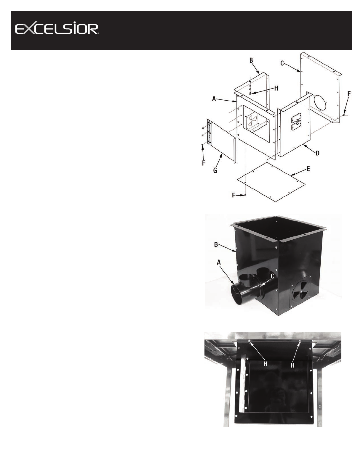
ASSEMBLING DUST C LLECTI N B X
1) Assemble front panel (A) Fig.1, side panels (B & D), rear panel (C) and
bottom panel (E) together using the short pan head screws (F).
2) Install the dust chute (A) Fig.2 to the rear panel (B) as shown using the
three longer pan head screws (C).
INSTALLING DUST C LLECTI N B X T TABLE
1) Install the Dust Collection box assembly to the underside of the table as
shown in Fig.3. Position the Dust Collection box under the table with the
front access door (G) Fig.1 facing towards the front of the router table.
Using 6 hex. bolts, spring washers and washers (H) Fig.1 & Fig.3 secure
Dust Collection box to table.
FIGURE 1
FIGURE 2
FIGURE 3
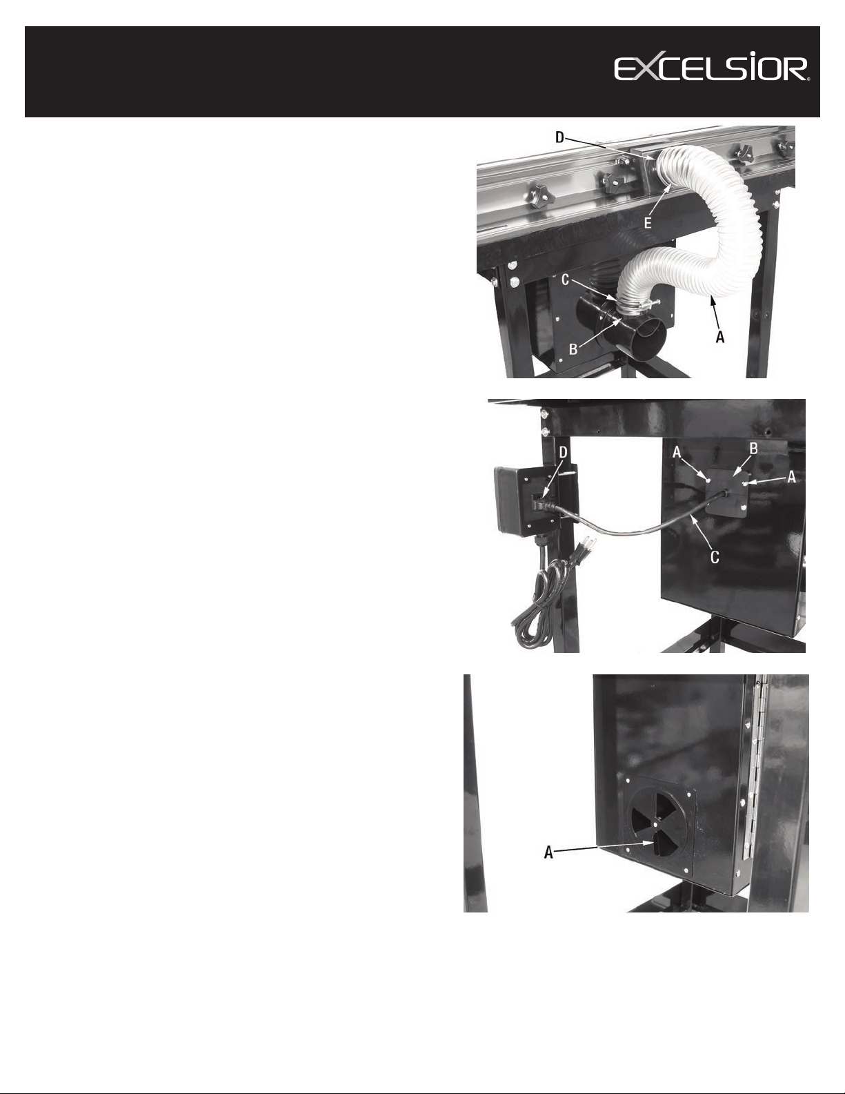
ASSEMBLY & ADJUSTMENTS
FIGURE 4
ASSEMBLY
INSTALLING DUST C LLECTI N H SE
1) Install the dust collection hose (A) Fig.4 over the side inlet (B) and secure
hose by tightening the hose clamp (C).
2) Install the other end of the collection hose over the dust chute on the rear
of the fence dust housing (D). Secure hose by tightening the hose clamp
(E).
INSTALLING R UTER P WER C RD IN THE C RD CLAMP SYSTEM
1) nce the router is installed in the Router Lift (mod. XL-125), undo 2 pan
head screws (A) Fig.5 and remove the top clamp plate (B).
2) Pass the router power cord (C) through the opening of the cord clamp
system, then reinstall the top clamp plate with the 2 pan head screws (A)
removed previously.
3) nce installed, connect the router power cord to the rear of the power
switch (D) which comes standard with the Floor Stand (mod. XL-085).
ADJUSTMENTS
ADJUSTING AIR VENT
This Dust Collection Kit comes with an adjustable air vent (A) Fig.6 which
can be opened or closed by simply turning the vent.
This vent allows the user to adjust the airflow and maximize dust collection.
The opening size should be based on the size and power of your dust
collector. The smaller the dust collector, the more the vent should be
opened to allow maximum airflow.
FIGURE 5
FIGURE 6
Table of contents
Popular Water Filtration System manuals by other brands

Wisy
Wisy LineAir 100 Installation and operating instructions

Schaffner
Schaffner Ecosine FN3446 Series User and installation manual

Pentair
Pentair FLECK 4600 SXT Installer manual

H2O International
H2O International H20-500 product manual

Renkforce
Renkforce 2306241 operating instructions

Neo-Pure
Neo-Pure TL3-A502 manual


