WATANABE ELECTRIC INDUSTRY AM-756 User manual

Instruction Manual MODEL AM-756 1/20
Enter Mode /
5 1/2 Digit Digital Meter Relay
AM-756
Instruction Manual
WARNING
This symbol indicates instances where
incorrect use may result in death or serious
injury, or cause serious damage to property.
CAUTION
This symbol indicates instances where
improper use may result in injury to the
operator or serious damage to property.
(1) The insulation class of this device is outlined below. Please ensure the
insulation class of this device satisfies your usage requirements before
setting up the device.
Basic insulation
Functional insulation
AC Power
Source
Comparative Output
Input
Sensor Power Source
External Control, BCD Output, Analog Output
DC Power
Source
Comparative Output
Input
Sensor Power Source
External Control, BCD Output, Analog Output
(2) Please do not disassemble this device or make improvements or repairs.
Doing so may cause sudden fire, electrocution or injury.
(3) In order to ensure power to equipment, including this device, is cut in
the event of failure, please ensure an external breaker is installed and
appropriately labeled so that it may be used to cut power to this device
when a malfunction occurs.
(4) In order to prevent device damage and failure, please ensure the voltage
used matches the device’s power rating.
(5) In order to prevent electrocution and device failure, please do not turn
the power on until all wiring has been completed.
(6) Before supplying power to this device, please ensure you check that the
device has been correctly wired. Incorrect wiring may cause device
failure, fire, electrocution or malfunction.
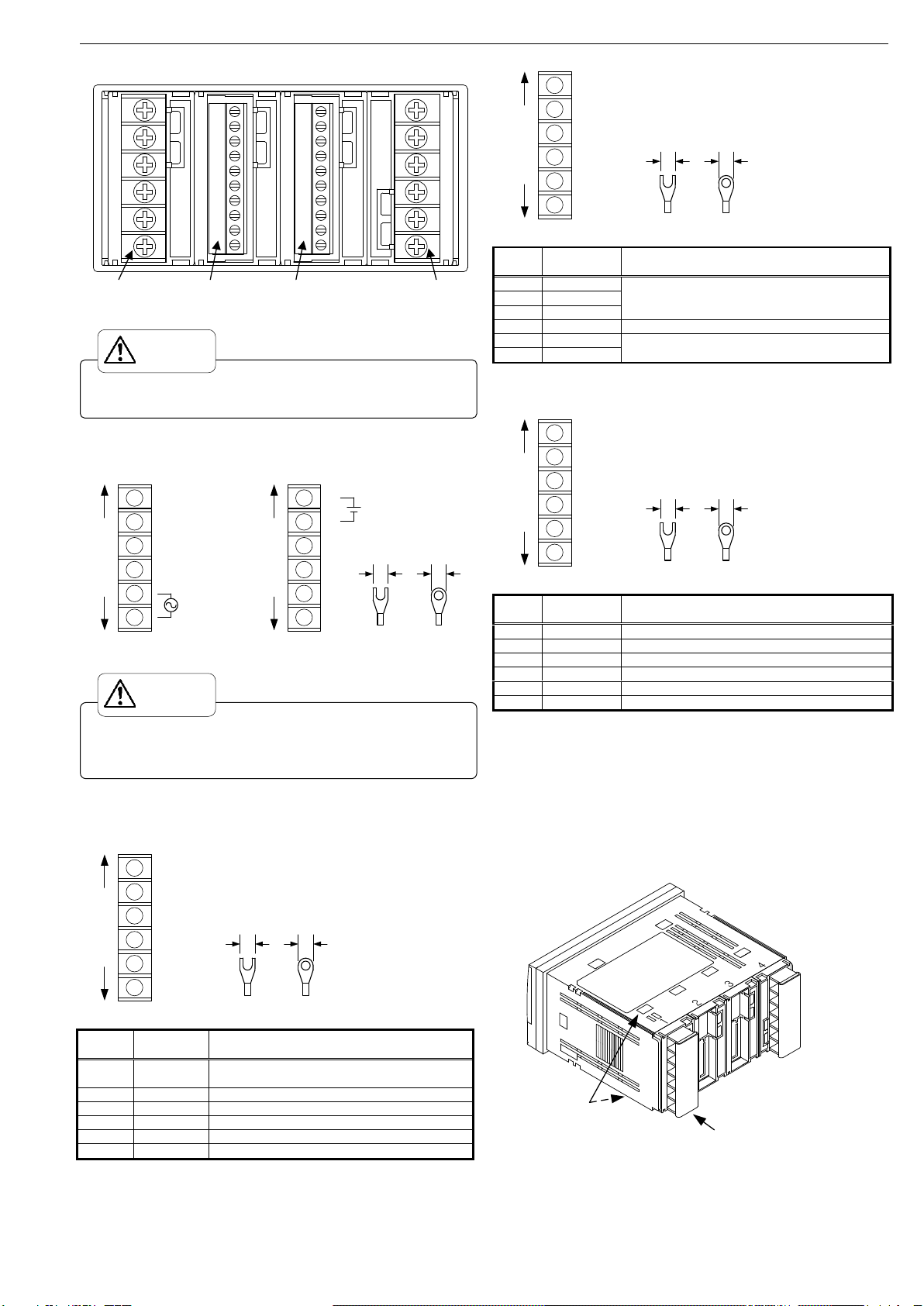
(7) In order to prevent electrocution or fire in the equipment, please check
that there is clearance around the device before activating power.
(8) Please do not touch the terminals while power is being supplied to the
device. Doing so may result in electrocution or malfunction.
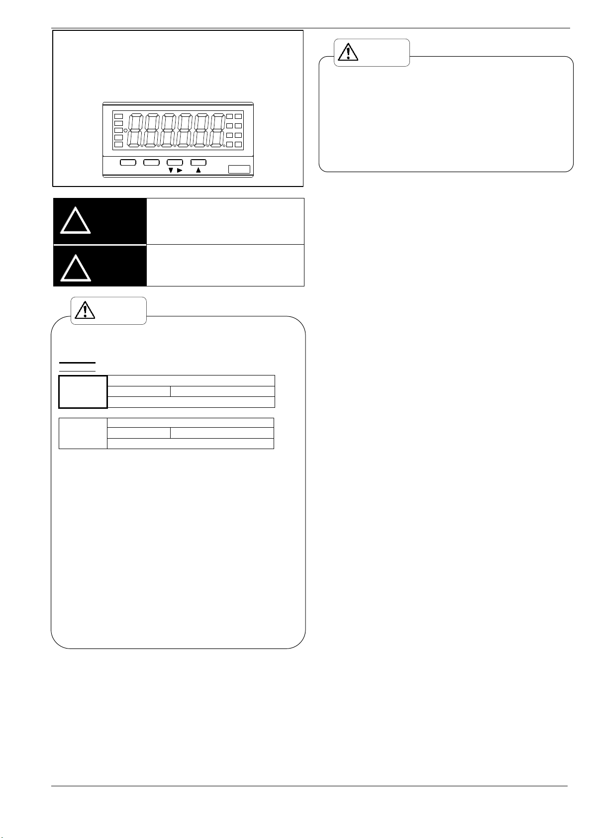
・Usage Conditions
Place of Installation: Indoors only
Rated Altitude: 2000m or less
Overvoltage Category: II
Pollution Level: 2
Operating Ambient Temperature and Humidity: 0~50°C 35~85%RH
(Non Condensing)
Vibration (durability): 10 to 55 Hz (Half amplitude 0.15mm)
X, Y, Z directions 30 min.
Impact (durability): 100m/s26 directions, 3 times each
(up and down, forward and back, left to right)
Protective Structure: Equivalent to IP40 (front section)
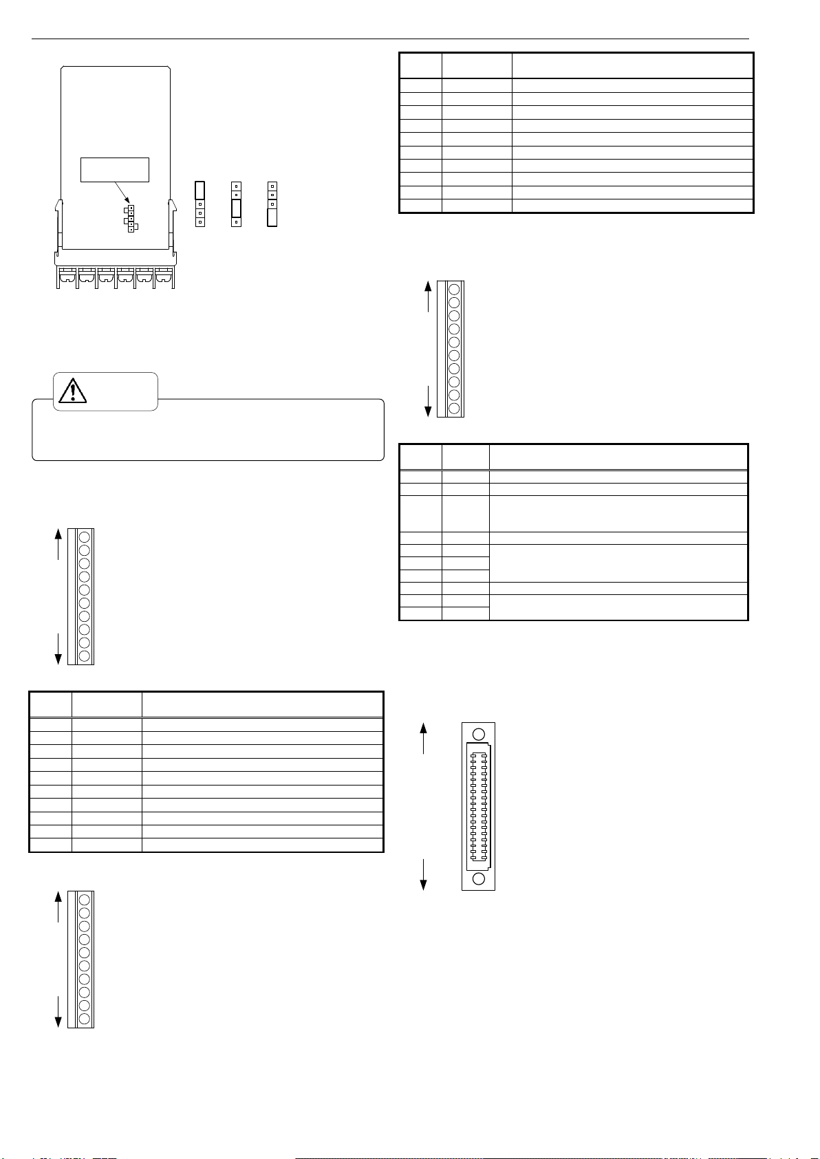
Connecting Wire Length: Input and output signal lines and control line –less
than 30m in length
・Safety Precautions
(1) Watanabe Electric Industry Co., Ltd assumes no responsibility for any
special damage, indirect loss or passive loss caused by this device.
(2) This device has been developed, designed and manufactured on the
premise that it is to be used as general machinery. Please ensure
attention is paid to safety by adopting such means as a fail-safe design
and a redundancy design, and by conducting regular checks on the
device, particularly when it is being used for purposes such as the
following, where safety is of utmost importance.
•Safety devices used for personal protection
•Rail, aviation and vehicular equipment
•Medical equipment
•Incineration systems, nuclear systems
•Other purposes conforming to the conditions above which require high
levels of safety
(3) Please do not use this device for applications which directly affect
human lives.
(4) When this device is to be used in conjunction with other products,
please check for conformance with specifications, provisions of law and
regulations before use to ensure compatibility.
(5) As the operating life of the comparative output relays varies greatly
depending on switching capacity and conditions, please ensure the
relays are used within their rated load and electrical life. Using
deteriorated relays could result in insulation failure between circuits or
burnout of the relays themselves.
(6) This device requires more than 40 minutes warm up time from when
power is activated in order to operate within its degree of accuracy.
(7) Please do not wipe this device with alcohol, paint thinner, benzene,
acetone or other organic solvents. When wiping the device, please use
a neutral detergent.
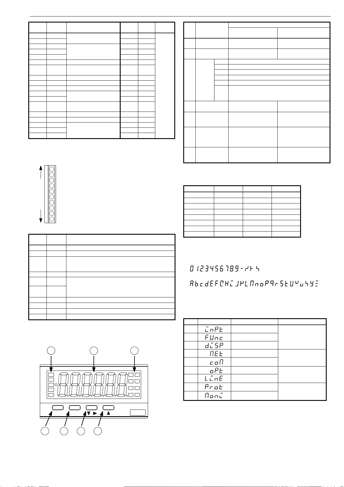
・Table of Contents
1 BEFORE USE ..............................................................................................2
2 INSTALLATION..........................................................................................2
3 TERMINAL DESCRIPTION AND CONNECTION METHOD..................3
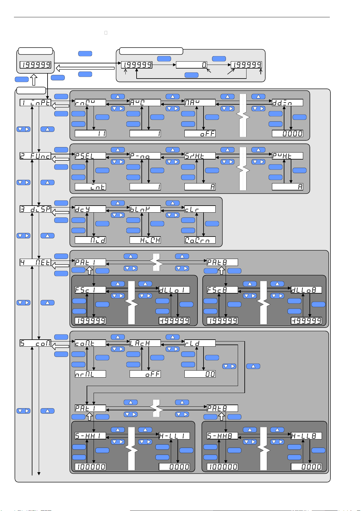
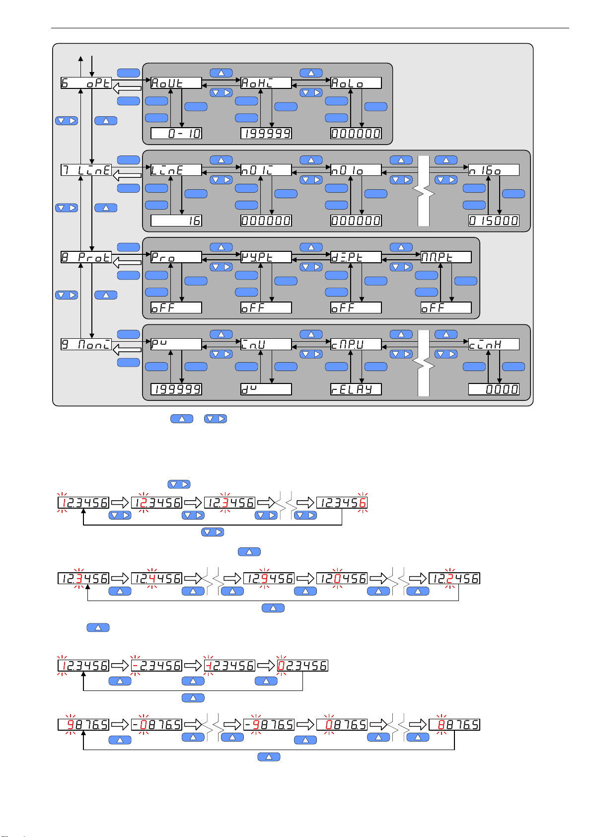
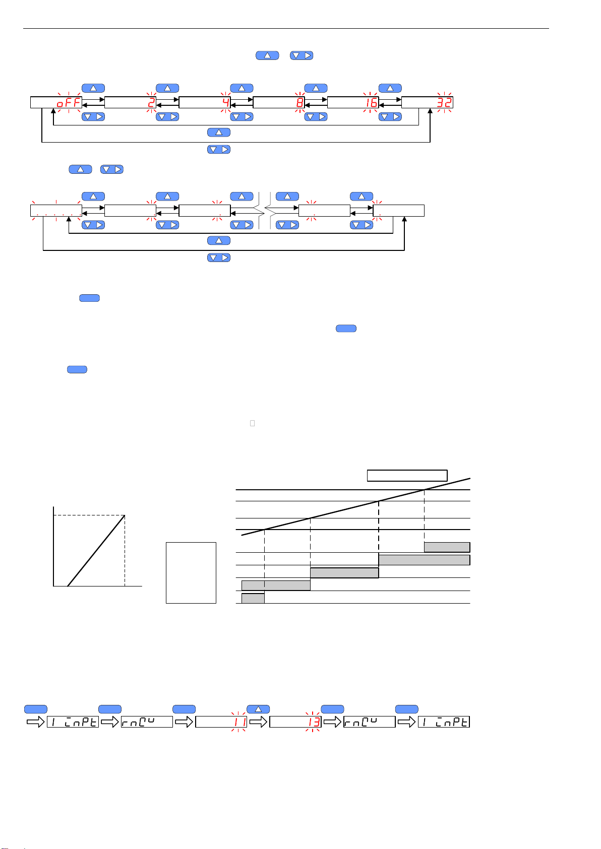
4 SETTING OF PARAMETERS.....................................................................5
5 EXAMPLE DEFAULT SETTING................................................................8
6 PARAMETER LIST...................................................................................10
7 FUNCTION LIST.......................................................................................14
8 SPECIFICATIONS.....................................................................................18
9 TROUBLE SHOOTING.............................................................................19
10 TIMING CHART......................................................................................19
11 WARRANTYAND AFTER-SALES SERVICE .......................................20
(1) Application of voltage or current exceeding the maximum input
tolerance may damage the device.
(2) Please ensure the voltage used is within the specified voltage range.
Failure to do so may cause fire, electrocution or malfunction.
(3) Please note that the contents of this manual are subject to change
without notice as the product is upgraded.
(4) The information contained herein is considered accurate to the best of
our knowledge. However, should there be any errors or omissions,
please contact the distributor or our company.
(5) After reading this manual, please keep it readily available for future
reference.
Watanabe Electric Industry Co., Ltd.
2022.07 ED-34880e
CAUTION
!
!
WARNING

Instruction Manual MODEL AM-756 2/20
1 Before Use
Thank you for purchasing the AM-756 Digital Meter Relay. Please ensure this
instruction manual is kept on hand for users of this device. Please inspect the
product for any signs of shipping damage and contact your dealer or Watanabe
Electric Industry Co., Ltd if anything comes to your attention.
1-1 Model Configuration
The model configuration of the AM-756 is shown below. Please check that the
product received matches the product ordered.
AM-756-□□-□□-□
Series Name
Comparative
Output
Options
Power 2.
Input
±199.999mV
±1999.99mV
±19.9999V
±199.999V
DV.
±19.9999mA23.
±199.999mA24.
DB.1to 5V
4to 20mA
±199.999mV
12 to 48VDC
100 to 240VAC1.
Off
External control
BCD output (TTL) + external control
BCD output (OC) + external control
Analog output + external control4.
3.
2.
1.
0.
2. Photocoupler output
Relay output1.
Off0.
Basic Model Name
1-2 Accessories
1 instruction manual
1 unit sticker
2 terminal covers for 6P terminal block (attached to main unit for shipment)
2 case attachment bands (attached to main unit for shipment)
・When BCD output is included as an option:
1 connector (8822E-036-171-F (manufactured by KEL))
2 Installation
2-1 Panel Cutout Size
The panel cutout size for mounting the AM-756 Digital Meter Relay is shown
in the diagram below.
Min. 120mm
Min. 70mm
+0.6
-0
45
92 -0
+0.8
2-2 External Dimensions
48
96
91.5
102.5
77
86.5
(97.5)
21.4 11
(0.5)
(2)
ModeEnter /
88.5
2-3 Mounting the Unit on the Panel
1) After removing the mounting bands from the
main unit, please insert the unit from the front side
of the panel.
2) Fix the unit in place from the rear of the panel
using the mounting bands to the left and right.
(1) Panel board thickness should be 0.8 to 5mm.
(2) Please do not install the device in the following locations.
・Locations with sudden changes in temperature resulting in
condensation.
•Locations with corrosive gases (particularly sulfide gas, ammonia
etc.) or flammable gases.
•Locations where the main unit may be subjected to vibration or
impact.
•Locations where the unit may come in contact with water, oil,
chemicals, steam or vapor.
•Locations with high concentrations of dust, salinity or iron particles.
•Locations with large inductive interference resulting in static
electricity, magnetic fields or noise.
•Locations exposed to direct sunlight.
•Locations where heat accumulation from radiant heat and other
sources occurs.
(3) In order to ensure heat dissipation is not obstructed, please allow room
around the device for heat to be released and ensure the device’s
ventilation holes and surroundings are not obstructed. When
installing this device inside other equipment, check the heat release to
ensure the temperature inside the equipment does not exceed 50°C.
(4) Please install this device horizontally.
CAUTION

Instruction Manual MODEL AM-756 3/20
3 Terminal Description and Connection Method
3-1 Rear View
Input unit Comparative
output unit
Optional unit Power unit
3-2 Power Connection
M3 screw terminal (terminal cover included)
NC
Top
Bottom
AC power drive
100 to 240VAC
±10%
12 to 48VDC
±10%
NC
NC
NC
1
2
3
4
5
6
NC
NC
+
DC power drive
ー
NC
NC
1
2
3
4
5
6
Applicable crimp
terminal
Max. 5.8 Max. 5.8
Top
Bottom
Recommended
torque : 0.5Nm
*NC Terminal: unconnected
3-3 Input Connection
M3 screw terminal (terminal cover included)
3-3-1 DV Range (Direct voltage input)
11 HI
11 LO
14 HI
12,13,14 LO
13 HI
12 HI
1
2
3
4
5
6
Max. 5.8 Max. 5.8
Top
Bottom
Applicable crimp
terminal
Recommended
torque : 0.5Nm
Terminal
No.
Name
Details
1
14 HI
±199.99V input (14 range) + terminal
2
12,13,14 LO
12, 13, 14 range - terminals
3
13 HI
±19.9999V input (13 range) + terminal
4
12 HI
±1.99999V input (12 range) + terminal
5
11 HI
±0.199999V input (11 range) + terminal
6
11 LO
±0.199999V input (11 range) - terminal
The input range settings parameters can be used to change the input range.
* Please do not connect anything to terminals other than those for the range
used.
Factory Setting: 11 ranges (± 0.199999V)
3-3-2 23, 24 Range (Direct current input)
LO
LO
NC
NC
NC
HI
1
2
3
4
5
6
Max. 5.8 Max. 5.8
Top
Bottom
Applicable crimp
terminal
Recommended
torque : 0.5Nm
Terminal
No.
Name
Details
1
NC
Unconnected
* Please do not use these terminals as relay terminals.
2
NC
3
NC
4
HI
+ Terminal
5
LO
- Terminals (connected internally)
6
LO
* Input range settings cannot be made.
3-3-3 DB Range (Process input)
Top
Bottom +EXC
-EXC
2A HI
LO
1V HI
11 HI
1
2
3
4
5
6
Max. 5.8 Max. 5.8
Applicable crimp
terminal
Recommended
torque : 0.5Nm
Terminal
No.
Name
Details
1
2A HI
4 to 20mA(±20mA) input (2A range ) + terminal
2
LO
- terminal
3
1V HI
1 to 5 V (±5V) input (1V range) + terminal
4
11 HI
±0.199999V input (11 range) + terminal
5
+EXC
Sensor power output + terminal
6
-EXC
Sensor power output - terminal
The input range settings parameters can be used to change the input range.
* Please do not connect anything to terminals other than those for the range
used.
Factory Setting: 1V range (±5V)
・Switching Sensor Power Voltage
This device is set to a factory setting of +24V. Therefore, when using the
device at +12V and +10V, please adjust the sensor power voltage according to
the instructions below.
(1) Turn off the device and leave for a minimum period of 10 minutes. Next,
pushing in the upper and lower hooks on the case, pull out the input unit.
Hooks
(also located on bottom) Input unit
(1) Please ensure supply voltage is within device’s power rating and that
power-up and cut-off are instantaneous.
(2) Please wait for ten seconds or more before activating power each time.
(3) Please do not use the NC terminals as relay terminals.
(1) Units may not be changed by the customer.
(2) Do not use different models of these units.
CAUTION
CAUTION

Instruction Manual MODEL AM-756 4/20
(2) Switch the sensor power switch socket as shown in the diagram below.
+12V
+24V
+10V
CN3
DB range input unit
Sensor power
switch socket
+24V +12V +10V
(3) After completing the switch, install the input unit according to the guides
found on the interior of the main unit case.
(4) Connect the input unit connector (female) to the main unit connector
(male) ensuring they are firmly connected.
3-4 Comparative Output Connection
3.81mm pitch European terminal board
3-4-1 Relay Output
HH a
1
2
3
4
5
6
7
8
9
10
HH c
HI a
HI c
GO a
GO c
LO a
LO c
LL a
LL c
Adaptable wire: AWG24 to 16
Length of stripped wire: 6 to 7mm
Top
Bottom
Recommended torque : 0.18Nm
Terminal
No.
Name
Details
1
HH a
HH Output relay a-contact terminal
2
HH c
HH Output relay COM terminal
3
HI a
HI Output relay a-contact terminal
4
HI c
HI Output relay COM terminal
5
GO a
GO Output relay a-contact terminal
6
GO c
GO Output relay COM terminal
7
LO a
LO Output relay a-contact terminal
8
LO c
LO Output relay COM terminal
9
LL a
LL Output relay a-contact terminal
10
LL c
LL Output relay COM terminal
3-4-2 Photocoupler Output
HH C
1
2
3
4
5
6
7
8
9
10
HH E
HI C
HI E
GO C
GO E
LO C
LO E
LL C
LL E
Top
Bottom
Adaptable wire: AWG24 to 16
Length of stripped wire: 6 to 7mm
Recommended torque : 0.18Nm
Terminal
No.
Name
Details
1
HH C
HH Output photocoupler Collector terminal
2
HH E
HH Output photocoupler Emitter terminal
3
HI C
HI Output photocoupler Collector terminal
4
HI E
HI Output photocoupler Emitter terminal
5
GO C
GO Output photocoupler Collector terminal
6
GO E
GO Output photocoupler Emitter terminal
7
LO C
LO Output photocoupler Collector terminal
8
LO E
LO Output photocoupler Emitter terminal
9
LL C
LL Output photocoupler Collector terminal
10
LL E
LL Output photocoupler Emitter terminal
3-5 Option Connection
3-5-1 External Control
3.81mm pitch European terminal board
S/H
1
2
3
4
5
6
7
8
9
10
PH
DZ
R.RES
PSEL0
PSEL1
PSEL2
COM
NC
NC
Top
Bottom
Adaptable wire: AWG24 to 16
Length of stripped wire: 6 to 7mm
Recommended torque : 0.18Nm
Terminal
No.
Name
Details
1
S/H
Start/Hold control terminal
2
PH
Peak hold control terminal
3
DZ
Digital zero control terminal
* Becomes effective when parameters settings are set to
external control
4
R.RES
Relay reset control terminal
5
PSEL0
Pattern select control terminals 0 to 2
* Becomes effective when parameters settings are set to
external control
6
PSEL1
7
PSEL2
8
COM
External control common terminal
9
NC
Do not connect anything to these terminals.
Please do not use NC terminals as relay terminals.
10
NC
3-5-2 BCD Output + External Control
1.27mm pitch, one-touch insertion/ejection, 2 piece connector (manufactured
by KEL)
Receptacle Section: 8822E-036-171-F (manufactured by KEL)
(accompanying item)
1048
1042
1038
1032
1028
1022
1018
1012
1051
1044
1041
1034
1031
1024
1021
1014
1011
1004
1008
1002
1001 POL
OVER PC
D.COM D.COM
ENA S/H
PH DZ
PSEL0
PSEL2
COM
R.RES
PSEL1
COM
Receptacle section adaptable wire
1.27mm pitch universal flat cable
(AWG28)
1
2
3536
Top
Bottom
Please turn off the device and wait for a minimum of 10 minutes before
commencing any work on the device. Failure to do so may result in
electrocution or fire.
CAUTION

Instruction Manual MODEL AM-756 5/20
Terminal
No.
Name
Details
Terminal
No.
Name
Details
1
COM
External control common
terminal
19
1008
BCD
data
output
2
COM
20
1011
3
PSEL2
Pattern select control
terminals 0 to 2 *1
21
1012
4
PSEL1
22
1014
5
PSEL0
23
1018
6
R.RES
Relay reset control terminal
24
1021
7
DZ
Digital zero control terminal
*1
25
1022
8
PH
Peak hold control terminal
26
1024
9
S/H
Start/Hold control terminal
27
1028
10
ENA
BCD enable input
28
1031
11
D.COM
BCD common terminals
29
1032
12
D.COM
30
1034
13
PC
BCD printing command
signal
31
1038
14
OVER
BCD over range output
32
1041
15
POL
BCD polarity output
33
1042
16
1001
BCD data output
34
1044
17
1002
35
1048
18
1004
36
1051
*1 Becomes effective when parameters settings are set to external control
3-5-3 Analog Output + External Control
3.81mm pitch European terminal board
S/H
1
2
3
4
5
6
7
8
9
10
PH
DZ
R.RES
PSEL0
PSEL1
COM
VOUT+
IOUT+
AO-
Top
Bottom
Adaptable wire: AWG24 to 16
Length of stripped wire: 6 to 7mm
Recommended torque : 0.18Nm
Terminal
No.
Name
Details
1
S/H
Start/Hold control terminal
2
PH
Peak hold control terminal
3
DZ
Digital zero control terminal
* Becomes effective when parameters settings are set to
external control
4
R.RES
Relay reset control terminal
5
PSEL0
Pattern select control terminals 0, 1
* Becomes effective when parameters settings are set to
external control
* PSEL2 Terminal is permanently OFF
6
PSEL1
7
COM
External control common terminal
8
VOUT+
Analog output (voltage) + terminal
9
IOUT+
Analog output (current) + terminal
10
AO-
Analog output - terminal
4 Setting of Parameters
4-1 Component Names and Functions
Enter Mode /
HH
HI
GO
LO
LL
RE
PH
DZ
TZ P3
P2
P1
ME
1 2 3
4 5 6 7
No.
Name
Main Functions
During Measurement
Mode
During Settings Mode
1
Comparative
Output Display
Displays comparative
judgment results
Extinguished
(Comparative output OFF)
2
Main Display
Displays measurement
values
Displays group name,
parameters, set values
3
Function
Indicators
RE
Unused
PH
Lights up when peak hold control terminal is activated
DZ
Lights up when digital zero function is activated
TZ
Lights up when tracking zero function is activated
ME
Lights up when digital zero backup is activated
P1
P2
P3
Pattern select function pattern number indicator
(Refer to chart below)
4
Enter Key
Switches to setting mode
(long key press)
Return, cancels changes to
set values
5
Mode Key
Switches to maximum /
minimum value display
(long key press)
Select,
Enter
6
Shift / Decrement
Key
Digital zero control *1
(long key press)
Shifts to the next parameter
down,
Changes number of digits in
settings
7
Increment Key
Switches pattern select
number(long key press) *1
Shifts to the next parameter
up,
Positive settings
*1 Function becomes effective when the parameters are set to enable front
panel key settings
・Pattern Number Display
Pattern No.
P1 Display
P2 Display
P3 Display
1
-
-
-
2
P1
-
-
3
-
P2
-
4
P1
P2
-
5
-
-
P3
6
P1
-
P3
7
-
P2
P3
8
P1
P2
P3
4-2 Display and Character Representations
Indications on the main display and their corresponding characters are as
follows.
0
1
2
3
4
5
6
7
8
9
-
/
A
B
C
D
E
F
G
H
I
J
K
L
M
N
O
P
Q
RR
S
T
U
V
W
X
Y
Z
+
&
4-3 Parameter Groups
The parameters are classified into the following groups in accordance with
their main objectives. When changing the parameters, bring up the display
for the group to which the parameter in question belongs.
No.
Group Name
Setting Details
Group Classification
1
Input
Condition data
2
Function
3
Display
4
Display scaling
Pattern data *3
5
Comparative output *1
6
Option*2
Condition data
7
Linearize
8
Protect
-
9
Monitor
*1 The “COM” group is not displayed when there is no comparative output.
*2 The “OPT” group is not displayed when there is no option, and during
external control.
*3 Some “COM” group parameters are classified as condition data.
Table of contents